Advertisement
Quick Links
Advertisement

Related Manuals for John Lewis SBSKITB


Summary of Contents for John Lewis SBSKITB
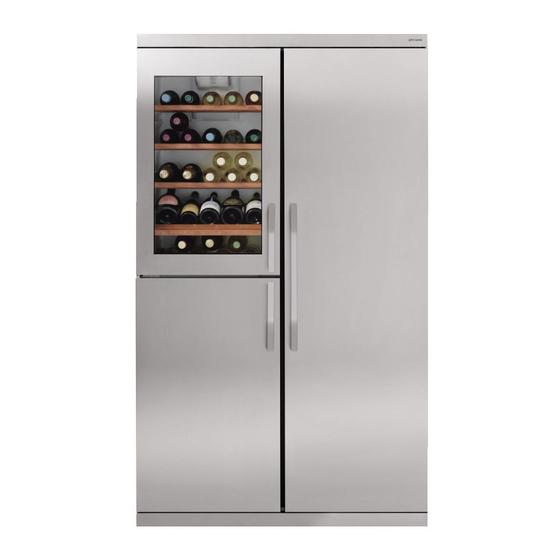
- Page 1 SBSKITB Side by Side Instruction manual...
- Page 2 Important information • Do not install the unit on your own or have unqualified personnel install it. • Improper installation may result in damage, malfunctioning or risk of electric shock. • This Side by Side unit must have the cooler section on the right side and the beverage storage/freezer section on the left side;...
-
Page 3: Tools Required For Installation
Tools required for installation (not supplied) - Page 7 • Carefully place the unit on the floor, following the instructions on the packaging to make sure the unit is facing upwards. • Open the bottom part of packaging and remove the corner protection. • «A» Screw the M8 nuts (bag «4») on the respective front feet. •...
- Page 8 • Glue the spacer sponge on the right side of the wine cooler-freezer, using the distances indicated in the fig. under neath.
- Page 9 • Bring the units near to each other. • «A» If necessary adjust the front feet so that the units are both the same height. • «B» Insert the bottom “L” joining bracket. • «C» Fix the bracket with four M5x18 screws (bag «2»).
- Page 10 • «A» Fix the joining bracket with four 4.2x13 self-tapping screws (bag «3») using the holes in the sides. • The bracket must be positioned so that the side of the bracket with the hole in the centre part protrudes as shown in fig.
- Page 11 • «A» Ensure the front feet are the same height, to level the appliance.Verify the position with a level. • «B» Lock the M8 nuts.
- Page 12 • If it is necessary to amend the level of the doors, or one single door, partially unscrew the hinge screws, related to the door to be adjusted, and move the hinge as indicated in the illustration below. • Repeat the operations for each single door until a correct alignment is obtained.
- Page 13 • Before proceeding with the assembly of the top remove the protective film. • «A» Position the top so that the bottom front part fits under the top hinges. • «B» Push the top so that its rear welt is touching the back of the units. •...
- Page 14 • Fit the trim “11” between the two units by pressing along the entire profile, see figure below.
- Page 15 • Before proceeding with the fixing of the plinth “8” remove the protective film. • Fit the plinth “8” so that the inner hook couples with the joining bracket as shown in the illustration.
- Page 16 • Fix the front of the top and kickplate with M5x12 screws (bag «1»).
- Page 17 • Before proceeding with the fixing of the side strips “9,10” remove the protective film. • Insert the front end of the side strip behind the plinth, see fig.“A”. • Align the outside of the side strip with the side of the unit and fix it with a 4.2x13 self-tapping screw “3” (bag «3»).
- Page 18 • Fit the three handles, as shown in figures A, B and C. • The screws and grub screws are included in the handle-kit. • Fix the two fitting blocks with two 4.2x13 self-tapping screws for each (bag «3» ). •...
- Page 19 You should also ensure that air can circulate freely around the back and the top of the cabinet. Position the assembled Side by Side: • At least 50 mm from the rear wall. • At least 150 mm from any overhanging kitchen furniture. •...
- Page 20 John Lewis Partnership 171 Victoria Street London SW1E 5NN www.johnlewis.com 10/07 2221 055-10...