Table of Contents
Advertisement
Quick Links
Advertisement
Table of Contents

Related Manuals for LevelOne FCS-1150


Summary of Contents for LevelOne FCS-1150
- Page 1 Zoom Network Camera Hardware User Manual FCS-1150, FCS-1160 Ver. 2014/05/27...
-
Page 2: Table Of Contents
Hardware Manual Table of Contents Precautions ............... 4 Safety Instructions ....................6 Introduction ..............7 The List of Models ....................7 Package Contents ..................... 7 Physical Description ....................8 Before Installation ............10 Connecting a Power Adapter (Optional) ............. 10 Connecting the DI/DO and Audio Devices (Optional) ........ - Page 3 Hardware Manual Accessing the Camera............ 24 Configure the IP Addresses ................... 24 Access the Camera ....................27...
-
Page 4: Precautions
Hardware Manual Precautions Read these instructions You should read all the safety and operating instructions before using this product. Heed all warnings You must adhere to all the warnings on the product and in the instruction manual. Failure to follow the safety instruction given may directly endanger people, cause damage to the system or to other equipment. - Page 5 Hardware Manual Federal Communications Commission Statement This equipment has been tested and found to comply with the limits for a class B digital device, pursuant to Part 15 of the FCC Rules. These limits are designed to provide reasonable protection against harmful interference in a residential installation.
-
Page 6: Safety Instructions
Hardware Manual Safety Instructions Cleaning Disconnect this video product from the power supply before cleaning. Attachments Do not use attachments not recommended by the video product manufacturer as they may cause hazards. Do not use accessories not recommended by the manufacturer Only install this device in a dry place protected from weather Servicing Do not attempt to service this video product yourself. -
Page 7: Introduction
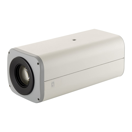
Zoom Network Camera, 5-Megapixel, PoE 802.3af, Day & Night, FCS-1160 12x, WDR Zoom Network Camera, 3-Megapixel, PoE 802.3af, Day & Night, FCS-1150 12x, WDR From the installation perspective, these models are very similar; therefore one manual is used for all of them. -
Page 8: Physical Description
Hardware Manual Physical Description 1) Memory Card Slot Insert a memory card into this slot for local recording purposes. See How to Install / Remove the Memory Card on page 23 for more information. NOTE: Supports microSDHC and microSDXC cards. 2) Digital Input / Output (DI/DO) and Audio Input / Output This connector connects to digital input or output devices, such as an alarm trigger, panic button, etc., as well as audio input and output devices, such as microphones and speakers. - Page 9 Hardware Manual 3. In case of connectivity issues or abnormal video quality. How to do the reset? Using a pointed object, such as a paper clip, press and hold the reset button for at least 5 seconds or until the Power LED goes off. 5) Power LED The Power LED turns on when the camera is powered on and the system is running.
-
Page 10: Before Installation
Hardware Manual Before Installation This section describes the procedures in preparing the external devices that you can connect to the camera. The camera supports DC12V power input, Digital Input and Output (DI/DO), Audio Input and Output devices, as well as Serial Devices like a Pan-Tilt (PT) Scanner using the bundled terminal blocks. - Page 11 Hardware Manual 3. Connect the wire with the white stripe to the 12V pin and the other to the GND pin. 4. Tighten the screws of the 12V pin and the GND pins to secure the wire connection. 5. Set the prepared power adapter for connection later. Below is an example of a power adapter with an attached terminal block.
-
Page 12: Connecting The Di/Do And Audio Devices (Optional)
Hardware Manual Connecting the DI/DO and Audio Devices (Optional) Depending on your surveillance needs, you may connect digital input / output or audio input / output devices to your camera. The camera comes with one (1) terminal block for both digital and audio input/output devices. - Page 13 Hardware Manual The table below shows the DI/DO connection specifications: Device Connection design TTL - compatible logic levels To trigger (low) Logic level 0: 0V ~ 0.4V Voltage Normal (high) Logic level 1: 3.1V ~ 30V Current 10mA ~ 100mA Connection design Transistor (Open Collector) Voltage &...
- Page 14 Hardware Manual High Voltage DO Device Connection Even though the camera provides 12V power, this may not be enough for some high voltage DO devices, such as a ceiling light or a motor that opens or closes a gate. In this case, there is a need to connect an external relay.
-
Page 15: How To Connect Audio Devices
Hardware Manual How to Connect Audio Devices Audio input / output devices, such as an active microphone or speaker can be connected to the camera using the supplied terminal block. Press and hold the orange tab as you insert the wire through the pin slot, then release the orange tab to secure the wire. -
Page 16: Connecting A Serial Device (Optional)
Hardware Manual Connecting a Serial Device (Optional) The camera can be connected to a Pan-Tilt (PT) Scanner (Pan-Tilt Head) using the serial port connector. This allows the zoom camera to do pan and tilt using the Pelco-D protocol. Most PT scanners accept Pelco-D and Pelco-P protocol commands via RS-485 or RS-422 connection, which are both supported by your camera. - Page 17 Hardware Manual CAUTION: Incorrect wiring may cause damage to the connected devices. DISCLAIMER: The manufacturer will not be responsible for any damage caused by improper wiring. 2. Connect a ground wire to one of the GND terminal pin to complete the connection. For more information on connecting PT scanners, please refer to the Knowledge Base article downloadable from our website.
-
Page 18: Indoor Installation Procedures
Hardware Manual Indoor Installation Procedures This section describes the procedures in installing the camera indoors using PMAX-1105 indoor bracket (purchased separately). When using brackets from other manufacturers, check the installation guide included in the bracket to install the camera. NOTE: Some pictures in this documentation may slightly differ from the actual camera or accessories. -
Page 19: Step 2: Attach The Camera To The Bracket
Hardware Manual Step 2: Attach the Camera to the Bracket NOTE: The following images show the mounting bracket attached on the bottom side of the camera. Same procedures apply when attaching the mounting bracket on the top side. 1. If necessary, insert a memory card into the memory card slot of the camera with the metal contacts facing down. - Page 20 Hardware Manual 4. Tighten the hand knob until the camera is secured to the bracket. 5. Adjust the camera angle. 6. Tighten the knurled knob to fix the camera position.
-
Page 21: Step 3: Connect The Cable(S)
Hardware Manual Step 3: Connect the Cable(s) 1. Connect the network cable to the Ethernet port of the camera. 2. If necessary, connect the other external devices, such as DI/DO, PT scanner or power adapter to the camera. See Before Installation on page 10 for more information. -
Page 22: Step 4: Access The Camera Live View
Hardware Manual Step 4: Access the Camera Live View Accessing the Camera on page 24 for more information on how to access the Live View of the camera. -
Page 23: Other Accessories
Hardware Manual Other Accessories How to Install / Remove the Memory Card The camera supports local video recording or saving of snapshots to a memory card. NOTE: Supports microSDHC and microSDXC cards. How to Insert the Memory Card Insert a memory card into the card slot with the metallic contacts facing down the camera. Push the card until it clicks into place. -
Page 24: Accessing The Camera
Hardware Manual Accessing the Camera Configure the IP Addresses In order to be able to communicate with the camera from your PC, both the camera and the PC have to be within the same network segment. In most cases, it means that they both should have very similar IP addresses, where only the last number of the IP address is different from each other. - Page 25 Hardware Manual Double-click the mouse button on the camera model, the default browser of the PC is automatically launched and the IP address of the target camera is already filled in the address bar of the browser. If you work with our cameras regularly, then there is even a better way to discover the cameras in the network –...
- Page 26 Hardware Manual Use the default IP address of a camera: If there is no DHCP server in the given network, the user may have to assign the IP addresses to both PC and camera manually to make sure they are in the same network segment. When the camera is plugged into network and it does not detect any DHCP services, it will automatically assign itself a default IP: 192.168.0.100...
-
Page 27: Access The Camera
Hardware Manual Manually adjust the IP addresses of multiple cameras: If there are more than 1 camera to be used in the same local area network and there is no DHCP server to assign unique IP addresses to each of them, all of the cameras would then have the initial IP address of 192.168.0.100, which is not a proper situation for network devices –... - Page 28 Hardware Manual provided only for Microsoft Internet Explorer. The browser functionality comparison: Functionality Internet Explorer Other browsers Live Video Live Video Area Resizable PTZ Control Capture the snapshot Video overlay based configuration (Motion Detection regions, Privacy Mask regions) All the other configurations When using non-Internet Explorer browsers, free third-party software plug-ins must be installed to the PC first to be able to get the live video feed from the camera: Browser...
- Page 29 Hardware Manual The following examples in this manual are based on Internet Explorer browser in order to cover all functions of the camera. Assuming that the camera’s IP address is 192.168.0.100, you can access it by opening the Web browser and typing the following address into Web browser’s address bar: http://192.168.0.100 Upon successful connection to the camera, the user interface called Web Configurator would appear together with the login page.
- Page 30 Hardware Manual To check the firmware version through the Web Configurator, access the Setup page and click System > System Info. For further operations, please refer to the Firmware User Manual.