Table of Contents
Advertisement
Quick Links
Advertisement
Table of Contents

Related Manuals for LevelOne FCS-1121


Summary of Contents for LevelOne FCS-1121
-
Page 1: User Manual
LevelOne User Manual FCS-1121 Megapixel PoE Network Camera Ver 1.0... -
Page 2: General Public License
If you would like a copy of the GPL or other open source code in this software on a physical CD medium, LevelOne (Digital Data Communications) offers to mail this CD to you upon request, for a price of US$9.99 plus the cost of shipping. -
Page 3: Table Of Contents
Table of Contents Before You Use This Product ................ 2 Fixed Box Network Camera Overview .............. 3 Device Appearance Description ..............4 LED Behavior ................... 5 Installation ....................8 System Requirements ....................8 Camera Connection ......................9 Basic Connection (Without PoE) ............9 Power over Ethernet (PoE) Connection .......... - Page 4 User Management ................. 39 Firmware Upgrade ................. 40 Configuration ................40 Reset to default ................41...
-
Page 5: Before You Use This Product
Before You Use This Product The use of surveillance devices may be prohibited by law in your country. The Network Camera is not only a high-performance web-ready camera but also can be part of a flexible surveillance system. It is the user’s responsibility to ensure that the operation of such devices is legal before installing this unit for its intended use. -
Page 6: Fixed Box Network Camera Overview
In addition, the LevelOne IP camera can transmit the video to portable devices via other technology, for instance, WiMAX, 3G cell phone, NAS, Digital Frame and power line. -
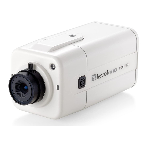
Page 7: Device Appearance Description
Device Appearance Description <Front Panel> Light Sensor Status LED WPS LED Built-in Microphone <Rear Panel> Ethernet RJ45 10/100 Socket Power Connector (AC24V in) (Link/Power LED embedded) Power Connector (DC12V in) Auto Iris Connector SD Card Extension I/O Reset Button Terminal Block Audio Out Microphone/Line In... -
Page 8: Led Behavior
LED Behavior Function LED Behavior Description Remark Hardware Front Left Status failure (Green) 1. Restoring settings Front Left Status Steady On 2. Normal (Green) Operation The LED can be 1. Power Off configured 2. Power On to be Status Unlighted till System unlighted setup... - Page 9 Extension I/O Terminal Block The Network Camera provides an extension I/O terminal block which is used to connect external input/output devices. The pin definitions are listed as below. Function Power +4.5V Digital Output Digital Input Ground RS-485 - RS-485 + DI/DO Diagram...
- Page 10 Hardware Reset Reset Button The reset button is used to reset the system or restore the factory default settings. Sometimes resetting the system can return the camera to normal operation. If the problems remain after reset, please restore the factory settings and install it again. Reboot: Please press and release the indented reset button within 1 second with paper clip or thin object.
-
Page 11: Installation
Installation System Requirements Operating System: Microsoft Windows XP Home Edition SP2 Microsoft Windows XP Professional SP2 Computer: IBM PC/AT Compatible CPU: Pentium 3GHz or faster Memory: 1024 MB or more Monitor: 1024 x 768 pixels or more, 24-bit True color or better Network Interface: 10/100Mbps Network interface card must be installed Web Browser:... -
Page 12: Camera Connection
Camera Connection Basic Connection (Without PoE) 1.1 If you have external devices such as sensors and alarms, please make connections with extension I/O terminal block. 1.2 Connect the camera to a switch via Ethernet cable. 1.3 Connect the supplied power cable from the camera to the power outlet. Please check your product package contains all the accessories listed in the foregoing Package Contents. -
Page 13: Power Over Ethernet (Poe) Connection
Power over Ethernet (PoE) Connection 1.1. When connecting to PoE-enabled switch The camera is PoE compliant and please connects the camera to a PoE-enabled switch via single Ethernet cable. 1.2. When connecting to a non-PoE switch Please connect the camera to a non-PoE switch via PoE Injector (optional). -
Page 14: Software Installation
Software installation In this manual, "User" refers to whoever has access to the Network Camera, and "Administrator" refers to the person who can configure the Network Camera and grant user access to the camera. After hardware connection checking, the users can run the Installation Wizard program included in the product CDROM to automatically search for the Network Camera in the Intranet. - Page 17 2. Do not check the box if user would like to check the hardware installation settings, Otherwise click “Skip the hardware installation” to skip the hardware connection checking, the program will automatically search for the Network Camera in the Intranet. Click “Start”...
- Page 18 4. Setting the Network Camera IP address User can either select simple mode or professional mode for network camera IP setting. If simple mode is selected, the easy configuration program will set up the connection automatically. If professional mode is selected, the user will need to configure the IP manually, The DHCP setting is recommended.
- Page 20 5. After finish setting, the connection successful or fail showed. If connection failed, user can either try again or quit the installation. User can either select "Start Web GUI" to continue or click “X” on the top right of the screen to finish the installation. Once installation is completed, the Administrator should proceed to the next section "Access to the Network Camera"...
-
Page 21: Access To The Network Camera
Access to the Network Camera Check Network Settings The Network Camera can be connected either before or immediately after software installation onto the Local Area Network. The Administrator should complete the network settings on the configuration page, including the correct subnet mask and IP address of gateway and DNS. -
Page 22: Authentication
Authentication After opening the Web browser and typing in the URL of the Network Camera, a dialogue window pops up to request a username and password. The user name and password for the Administrator are assigned as “admin/admin”. Installing plug-in For the initial access to the Network Camera in Windows, the web browser may prompt for permission to install a new plug-in for the Network Camera on the Internet Explorer. -
Page 23: Live View
Live View Live View is the default page that opens when accessing the Network Camera. Live video is displayed directly in the browser window. Stream1/Stream2 Channels The network camera offers simultaneous dual stream for optimized quality and bandwidth. To configure the codec compression and video resolution, please go to the Configuration->Camera/video/audio->Video to make the changes, or refer to the Video configuration on page 21. - Page 24 effect is not as good as that of the UDP protocol. UDP: This protocol allows for more real-time audio and video streams. However, network packets may be lost due to network burst traffic and images may be broken. Activate UDP connection when occasions require time-sensitive responses and the video quality is less important.
- Page 25 Real Size: click this button to view the object in real size. Press this button again to switch back to normal mode. Full Screen: Click this button to switch to full screen mode. Press “Esc” key to switch back to normal mode. Motion Detection Alert: Click this button to enable motion detection alert function.
-
Page 26: Configuration
Configuration Camera/Video/Audio Camera Camera Setting Brightness: Drag the slider bar to adjust the image brightness level, which ranges from -5 to +5. Contrast: Drag the slider bar to adjust the image contrast level, which ranges from -5 to Sharpness: Drag the slider bar to adjust the image sharpness level, which ranges from -5 to +5. -
Page 27: Video
Saturation: Drag the slider bar to adjust the image saturation level, which ranges from -5 to +5. Night Vision IR CUT: the Network Camera switches off the IR cut filter at all times for the sensor to accept the infrared light, thus helps improve low light sensitivity. Auto: The Network Camera automatically removes the filter by judging the level of ambient light. - Page 28 Stream 1 & Stream 2 Video Codec: The Network Camera offers three choices of video codec standards for real-time viewing: H.264, MPEG-4 and MJPEG. Video Resolution: select from the drop down list to choose the best resolution that fit your need. Frame Rate: Select from the drop down list of the frame rate, which ranges from 2 to 30 fps when H.264 or MJPEG is selected.
- Page 29 Video Overlay: Check to enable the timestamp function and select display position from the drop-down list if user wants date and time to be shown on the screen of the live video. User may also enable and enter the video description in text box; and select display position from the drop-down list if user wants to make a note about the network camera.
-
Page 30: Audio
Snapshot folder path: The destination for saving the snapshot files. Click browse to specify the saving path. Click Apply or Reset to take effect. Audio You can set up two separate streams for the Network Camera for different viewing devices. User can either enable or disable the audio function. If audio enable is selected, select the Audio codec from the drop down list. - Page 31 Click Apply or Reset to take effect.
-
Page 32: Network
Network IP Setting IP Setting: This section explains how to configure wired network connection for the Network Camera. There are several ways to setup the Network Camera over the Internet. The first way is to obtain an available dynamic IP address assigned by a DHCP server. The second way is to utilize a static The third way is to use PPPoE. -
Page 33: Upnp
to the LAN. Static IP: Select this option to manually assign a static IP address to the Network Camera. Enter the static IP address, Subnet mask, Default Gateway, Primary and Secondary DNS provided by your ISP. PPPoE (Point-to-point over Ethernet): Choose this connection type if you are connected to the Internet via a DSL Line. -
Page 34: Tzo
Click Apply or Reset to take effect. TZO: TZO is one kind of the DDNS providers. User can refer to the TZO.com: visit http://www.tzo.com/ to apply a dynamic domain account when selecting this DDNS provider. Enter the e-mail address, password and domain name when enabled the TZO. Click Apply or Reset to take effect. -
Page 35: Easy Link
Easy Link Easy Link – the IP camera had bundle with free Level1DNS service that allows user to remote access the IP camera via internet. The default domain name is MAC address, you can also register your own name on-line but it have to check the available first. The status will show the connection with Level1DNSTM service. -
Page 36: Notification Setting
Detection Setting: Select and enable the motion detection windows function. Easier to trigger event by higher the sensitivity value and lower the Threshold value. Notification: To react in response to particular events. A typical application is that when a motion is detected, the Network Camera sends buffered images to a FTP server, SMTP or Samba as notifications. - Page 37 email address, FTP site or samba. FTP: File Transfer Protocol (FTP) is often used as an application component to automatically transfer files for program internal functions. Select to send the media files to a FTP server when a trigger is activated. Enter the FTP IP address or hostname;...
- Page 38 Authentication: Select the authentication type from the drop-down list. Email Account: Enter the user name of the email account if necessary. Email Password: Enter the password of the email account if necessary. Click Apply or Reset to take effect. Samba: Select to send the network file system media files via network neighborhood when a trigger is activated.
-
Page 39: System
Click Apply or Reset to take effect. System System Log Log: To send a system log to the network camera when a trigger is activated. This page displays the system’s log in chronological order. The system log is stored in the Network Camera’s buffer area and will be overwritten when reaching a certain amount. -
Page 40: Date & Time Settings
Date & Time Settings Manual: The user can enter the date and time manually. Clone from PC: Sync with computer time; click clone to synchronize the date and time of the Network Camera with the local computer. The read-only date and time of the PC is displayed as updated. -
Page 41: Device Information
Device Information Video/Audio Setting: To view all the video/audio setting information about the network camera. Network Setting: To view all the network setting information about the network camera. System Information: To view all the system information about the network camera. -
Page 42: Maintenance
Maintenance User Management This section explains how to enable password protection and create multiple accounts. Privilege Setting: Enter the new user’s name and password. Select the privilege for new user account. Click Add to take effect. The administrator account name is “admin”, which is permanent and can not be deleted. -
Page 43: Firmware Upgrade
IP Filter IP Filter: Enable the IP filter and set of allow or deny IP address range to server. Click Add to list to add the IP range to the IP filter list. Click Apply or Reset to take effect. Firmware Upgrade This feature allows you to upgrade the firmware on your Network Camera. -
Page 44: Reset To Default
export. Click browse to indicate the location and file of the camera configuration and click import to import the configuration file back into the network camera. Reset to default Reset to default: Click Reset to Default to restore the network camera to factory default setting.