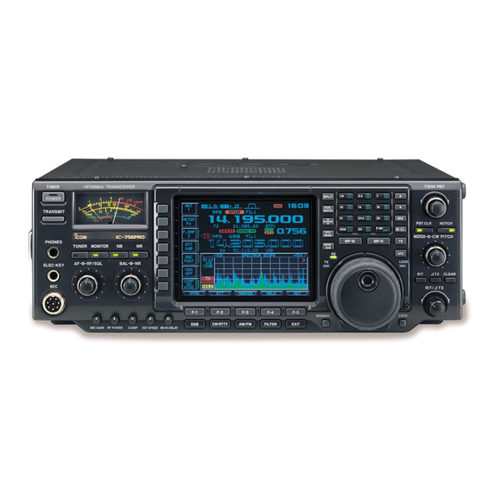
Icom IC-756PRO Service Manual
Hf/50mhz all band transceiver
Hide thumbs
Also See for IC-756PRO:
- Instruction manual (84 pages) ,
- Service manual (104 pages) ,
- Alignment procedure (13 pages)
Table of Contents
Advertisement
Quick Links
Advertisement
Table of Contents

Related Manuals for Icom IC-756PRO


Summary of Contents for Icom IC-756PRO
- Page 1 SERVICE MANUAL HF/50MHz ALL BAND TRANSCEIVER i756PRO...
- Page 2 NJM4558M IC-756PRO MAIN UNIT 5 pieces 6. DO NOT transmit power into a signal generator or a 8810005770 Screw BiH M3×8 ZK IC-756PRO Top cover 10 pieces sweep generator. Addresses are provided on the inside back cover for your 7. ALWAYS connect a 50 dB to 60 dB attenuator between convenience.
-
Page 3: Table Of Contents
TABLE OF CONTENTS SECTION 1 SPECIFICATIONS SECTION 2 INSIDE VIEWS SECTION 3 CIRCUIT DESCRIPTION 3 - 1 RECEIVER CIRCUITS ............3 - 1 3 - 2 TRANSMITTER CIRCUITS . -
Page 4: Specifications
SECTION 1 SPECIFICATIONS GENERAL RECEIVER • Frequency coverage: • Receive system : Triple-conversion superheterodyne Receive 0.030–60.000 MHz* • Intermediate frequencies: Transmit 1.800–1.999 MHz* 3.500–3.999 MHz* 1st IF frequency 64.455 MHz 7.000–7.300 MHz* 10.100–10.150 MHz* 2nd IF frequency 455 kHz 14.000–14.350 MHz* 18.068–18.168 MHz* 3rd IF frequency 36 kHz... -
Page 5: Inside Views
SECTION 2 INSIDE VIEWS • BOTTOM VIEW 2 - 1... - Page 6 • TOP VIEW 2 - 2...
-
Page 7: Circuit Description
The RF circuit has 11 LO signal to convert the receive signal frequencies into a bandpass filters and 1 low-pass filter. 64.455 MHz 1st IF signal. The IC-756PRO has two 1st mixer circuits for the dualwatch function. (1) 0.03–1.6 MHz The signals pass through the low-pass filter (L181–L183,... - Page 8 3-1-5 1ST IF CIRCUIT (RF UNIT) Some DC voltage from the noise detector circuit is fed back to the noise amplifiers (Q271–Q273) via the DC amplifiers The 1st IF circuit filters and amplifies the 1st IF signal. The (Q274, Q275). The DC amplifiers function as an AGC circuit 1st IF signal combined at L653 is applied to an MCF to reduce average noise.
- Page 9 [RF/SQL] setting level. quency of IF signal to electronically narrow the passband width. The IC-756PRO uses the DSP circuit for the digital The S-meter signal is applied to the main CPU (IC3501, pin PBT function and actually shifts the both lower and higher 108) and is compared with the threshold level set by the passbands of 3rd IF filter within ±1.8 kHz.
-
Page 10: Transmitter Circuits
3-2 TRANSMITTER CIRCUITS The filtered signals are then applied to the differential ampli- fiers (IC2301a/b) via the analog switch (IC2201) and T/R 3-2-1 MICROPHONE AMPLIFIER CIRCUIT switch (IC2291). (MAIN UNIT) The microphone amplifier circuit amplifies microphone audio (2) When FM/AM modes signals to a level needed for the DSP. - Page 11 3-2-5 IF AMPLIFIER AND MIXER CIRCUITS amplified signal is applied to one of 8 low-pass filters in the FILTER unit. (MAIN AND RF UNITS) The modulated 3rd IF signal from the DSP board (DTIF: 36 kHz) is applied to the 3rd mixer circuit (MAIN unit; IC221). 3-2-7 LOW-PASS FILTER CIRCUIT (FILTER UNIT) The applied 3rd IF signal is mixed with the 3rd LO signal The low-pass filter circuit contains 8 Chebyschev low-pass...
-
Page 12: Pll Circuits
The ALC bias voltage is also applied to the ALC meter ampli- 3-2-11 MONITOR CIRCUIT fier (IC551a, pin 2) to obtain an ALC meter signal (ALCL). (DSP BOARD AND MAIN UNIT) The amplified signal is passed through the analog switch (IC The microphone audio signals can be monitored to check 3631, pins 13, 14) and applied to the main CPU (IC3501, pin voice characteristics. - Page 13 VCO circuits (Q201, D201, The divided signal at the DDS circuit (IC101) is used for the D202), (Q221, D221, D222), (Q251, D251–D254) and marker signals with the IC-756PRO. (Q271, D271–D274). The reference signal for the DDS circuit (32.0 MHz) is divid-...
-
Page 14: Antenna Tuner Circuits
3-4 ANTENNA TUNER CIRCUITS (3) Tuning relays (TUNER unit) According to the operating frequency band and antenna 3-4-1 MATCHING CIRCUIT (TUNER UNIT) condition, tuning relays select the capacitors and coils. The matching circuit is a T-network. Using 2 tuning motors, the matching circuit obtains rapid overall tuning speed. -
Page 15: Scope Circuit
3-5 SCOPE CIRCUITS 3-6 POWER SUPPLY CIRCUITS 3-5-1 SCOPE RECEIVER CIRCUIT (RF UNIT) 3-6-1 PA UNIT A portion of the 64.455 MHz 1st IF signal from the 1st mixer LINE DESCRIPTION circuit (Q511–Q514: while receiving) or IF amplifier (Q751: The voltage from an external power supply via while transmitting) is amplified at the IF amplifiers (Q811, the common filter circuit (FILTER unit, L501, Q812), then mixed with the 77.8 MHz scope 2nd LO signal... -
Page 16: Logic Circuits
3-6-3 MAIN UNIT LINE DESCRIPTION Receive 8 V converted from the 14 V line and regulated by the R8V regulator circuit (Q601, Q602, D601). Transmit 8 V converted from the 14 V line and regulated by the T8V regulator circuit (Q611, Q612, D611). -
Page 17: Adjustment Procedures
SECTION 4 ADJUSTMENT PROCEDURES 4-1 PREPARATION BEFORE SARVICING I REQUIRED TEST EQUIPMENT EQUIPMENT GREDE AND RANGE EQUIPMENT GREDE AND RENGE Output voltage : 13.8 V DC Frequency range : 300–3000 Hz DC power supply Audio generator Current capacity : 30 A or more Measuring range : 1–500 mV Measuring range... -
Page 18: Pll Adjustments
4-2 PLL ADJUSTMENTS ADJUSTMENT MEASUREMENT POINT ADJUSTMENT ADJUSTMENT CONDITION VALUE UNIT LOCATION UNIT ADJUST • Display frequency: Any Connect a frequency 64.000000 MHz REFERENCE (R33 FREQUENCY • Turn L52 on the PLL unit to 4 rota- counter check for critical adjustment) tion downside for presetting. - Page 19 PLL ADJUSTMENTS—continued ADJUSTMENT MEASUREMENT POINT ADJUSTMENT ADJUSTMENT CONDITION VALUE UNIT LOCATION UNIT ADJUST S2LO • Display frequency: Any Connect an RF volt- 0 dBm or more Verify OUTPUT • Receiving meter to check point P901. LEVEL MARKER • Display frequency: Any Connect an oscillo- 4 Vp-p or more Verify...
-
Page 20: Receiver Adjustments
4-3 RECEIVER ADJUSTMENTS ADJUSTMENT MEASUREMENT POINT ADJUSTMENT ADJUSTMENT CONDITION VALUE UNIT LOCATION UNIT ADJUST • Display frequency: 14.100000 MHz Rear Connect an AC milli- Maximum audio output L513, RX PEAK • Mode : USB panel volt meter to [EXT level L721, •... - Page 21 • RF unit RF unit Bottom view of the transceiver L943 L513 RX peak adjustment L722 R516 L721 Mixer balance adjustment C555 FM distortion R616 adjustment C655 L613 RX peak adjustment • MAIN unit MAIN unit Bottom view of the transceiver L111 RX peak L112...
- Page 22 RECEIVER ADJUSTMENTS—continued ADJUSTMENT MEASUREMENT POINT ADJUSTMENT ADJUSTMENT CONDITION VALUE UNIT LOCATION UNIT ADJUST RECEIVER • Display frequency: 14.100000 MHz Rear Connect an AC milli- 1.0 V (0 dB) Front [AF] TOTAL GAIN • Mode : USB panel volt meter to [EXT unit control •...
- Page 23 • MAIN unit L272 Noise blanker L271 adjustment R271 R210 Receiver total gain CP271 adjustment Noise blanker check point • RF unit RF unit J841 Bottom view of the transceiver Spectrum scope pre-setting CP871 Spectrum scope R863 check point R872 Spectrum scope L833...
-
Page 24: Transmitter Adjustments
4-4 TRANSMITTER ADJUSTMENTS ADJUSTMENT MEASUREMENT POINT ADJUSTMENT ADJUSTMENT CONDITION VALUE UNIT LOCATION UNIT ADJUST IDLING • Display frequency: 14.100000 MHz Unsolder W29. 100 mA CURRENT • Mode : CW (key up) Connect an ammeter • Preset R11, R18 on the PA unit to to the unsoldering (for driver) max. - Page 25 • PA unit PA unit Ammeter Top view of the transceiver Idling current check point for drivers Unsoldering here Ammeter Idling current adjustment for finals Idling current adjustment for drivers Unsoldering here Idling current check point for finals • RF unit RF unit L307 TX peak...
-
Page 26: Tuner Adjustment
TRANSMITTER ADJUSTMENTS—continued ADJUSTMENT MEASUREMENT POINT ADJUSTMENT ADJUSTMENT CONDITION VALUE UNIT LOCATION UNIT ADJUST RESIDUAL • Display frequency: 29.60000 MHz Rear Connect Minimum power differ- L713, • Mode : FM panel power meter ence with minimum L712, • Filter : 15 kHz [ANT1] connector. - Page 27 • RF unit RF unit Bottom view of the transceiver L711 Residual AM L713 adjustment L712 • MAIN unit and DSP board DSP board MAIN unit CP503 Residual AM check point R2227 Bottom view FM deviation of the transceiver adjustment R2229 AM modulation adjustment...
-
Page 28: Parts List
SECTION 5 PARTS LIST [FRONT UNIT] [DISPLAY BOARD] ORDER ORDER DESCRIPTION DESCRIPTION 5080000450 LAMP SLU2LC1EX5B-TH Q1553 1510000510 S.TRANSISTOR 2SA1576A T106R Q1554 1530002060 S.TRANSISTOR 2SC4081 T107 R 5510000480 METER ME-40 (KL-293S-10) D421 1750000520 S.DIODE DAN222TL D422 1750000520 S.DIODE DAN222TL 8900009230 CABLE OPC-908 D423 1750000520 S.DIODE... -
Page 29: Display Board
[DISPLAY BOARD] [DISPLAY BOARD] ORDER ORDER DESCRIPTION DESCRIPTION R222 7030003440 S.RESISTOR ERJ3GEYJ 102 V (1 kΩ) R521 7030003470 S.RESISTOR ERJ3GEYJ 182 V (1.8 kΩ) R223 7030003440 S.RESISTOR ERJ3GEYJ 102 V (1 kΩ) R531 7030003470 S.RESISTOR ERJ3GEYJ 182 V (1.8 kΩ) R224 7030003440 S.RESISTOR ERJ3GEYJ 102 V (1 kΩ) - Page 30 [DISPLAY BOARD] [DISPLAY BOARD] ORDER ORDER DESCRIPTION DESCRIPTION R1127 7030003490 S.RESISTOR ERJ3GEYJ 272 V (2.7 kΩ) C824 4030006880 S.CERAMIC C1608 JB 1H 472K-T-A R1128 7030003670 S.RESISTOR ERJ3GEYJ 823 V (82 kΩ) C825 4030006880 S.CERAMIC C1608 JB 1H 472K-T-A ERJ3GEYJ 151 V (150 Ω) R1201 7030003340 S.RESISTOR C826...
-
Page 31: Mode Board
[DISPLAY BOARD] [MODE BOARD] ORDER ORDER DESCRIPTION DESCRIPTION DS621 5040002110 S.LED CL-200HR-C-TU 7030003540 S.RESISTOR ERJ3GEYJ 682 V (6.8 kΩ) DS622 5040002080 S.LED CL-200YG-C-TU 7030003480 S.RESISTOR ERJ3GEYJ 222 V (2.2 kΩ) DS623 5040002080 S.LED CL-200YG-C-TU 7030003520 S.RESISTOR ERJ3GEYJ 472 V (4.7 kΩ) DS624 5040002080 S.LED CL-200YG-C-TU... -
Page 32: Rit Board
[TEN-KEY BOARD] [RIT BOARD] ORDER ORDER DESCRIPTION DESCRIPTION 1590002310 S.TRANSISTOR DTC114EE TL 6510019970 S.CONNECTOR 52808-1090 1590002310 S.TRANSISTOR DTC114EE TL 1590002310 S.TRANSISTOR DTC114EE TL 1590002310 S.TRANSISTOR DTC114EE TL 2250000340 ENCODER EVQ-VCJF0324B 1590002310 S.TRANSISTOR DTC114EE TL 0910052300 PCB B 5405 7030003540 S.RESISTOR ERJ3GEYJ 682 V (6.8 kΩ) 7030003480 S.RESISTOR ERJ3GEYJ 222 V (2.2 kΩ) - Page 33 [RF UNIT] [RF UNIT] ORDER ORDER DESCRIPTION DESCRIPTION D191 1750000440 S.DIODE 1SV263-TL L212 6200002990 S.COIL NL 322522T-2R2J-3 D192 1790000620 S.DIODE MA77 (TX) L213 6200003090 S.COIL NL 322522T-2R7J-3 D211 1750000440 S.DIODE 1SV263-TL L214 6200008780 S.COIL ACL3225S-3R9K D212 1790000620 S.DIODE MA77 (TX) L215 6200008790 S.COIL ACL3225S-4R7K...
- Page 34 [RF UNIT] [RF UNIT] ORDER ORDER DESCRIPTION DESCRIPTION ERJ12YJ331H (330 Ω) L561 6200003000 S.COIL NL 322522T-R22J-3 R141 7030008180 S.RESISTOR L562 6200003020 S.COIL NL 322522T-R33J-3 R142 7030003680 S.RESISTOR ERJ3GEYJ 104 V (100 kΩ) L563 6200001830 S.COIL NL 322522T-100J R143 7030003480 S.RESISTOR ERJ3GEYJ 222 V (2.2 kΩ) L564 6180002970 S.COIL...
- Page 35 [RF UNIT] [RF UNIT] ORDER ORDER DESCRIPTION DESCRIPTION R634 7030003480 S.RESISTOR ERJ3GEYJ 222 V (2.2 kΩ) R863 7310002580 S.TRIMMER RV-108 (104) R635 7030003560 S.RESISTOR ERJ3GEYJ 103 V (10 kΩ) R864 7030003700 S.RESISTOR ERJ3GEYJ 154 V (150 kΩ) ERJ3GEYJ 470 V (47 Ω) R637 7030003280 S.RESISTOR R865...
- Page 36 [RF UNIT] [RF UNIT] ORDER ORDER DESCRIPTION DESCRIPTION C171 4030008470 S.CERAMIC C1608 JB 1H 272K-T-A C359 4030011600 S.CERAMIC C1608 JB 1C 104KT-N C172 4030009880 S.CERAMIC C1608 JB 1H 682K-T-A C371 4030006880 S.CERAMIC C1608 JB 1H 472K-T-A C173 4030009980 S.CERAMIC C1608 JB 1H 152K-T-A C372 4030007110 S.CERAMIC C1608 CH 1H 680J-T-A...
- Page 37 [RF UNIT] [RF UNIT] ORDER ORDER DESCRIPTION DESCRIPTION C601 4030007070 S.CERAMIC C1608 CH 1H 330J-T-A C775 4030007040 S.CERAMIC C1608 CH 1H 180J-T-A C602 4030007040 S.CERAMIC C1608 CH 1H 180J-T-A C781 4030011600 S.CERAMIC C1608 JB 1C 104KT-N C603 4030007080 S.CERAMIC C1608 CH 1H 390J-T-A C783 4030011600 S.CERAMIC C1608 JB 1C 104KT-N...
-
Page 38: Main Unit
[RF UNIT] [MAIN UNIT] ORDER ORDER DESCRIPTION DESCRIPTION J831 6510007020 CONNECTOR TMP-J01X-V6 Q276 1530002060 S.TRANSISTOR 2SC4081 T107 R J841 6510007020 CONNECTOR TMP-J01X-V6 Q277 1590002710 S.TRANSISTOR UMH11NTN J901 6510007020 CONNECTOR TMP-J01X-V6 Q278 1590002530 S.TRANSISTOR UN911H (TX) J951 6510019990 S.CONNECTOR 52808-2290 Q331 1540000470 S.TRANSISTOR 2SD1801S-TL Q333... - Page 39 [MAIN UNIT] [MAIN UNIT] ORDER ORDER DESCRIPTION DESCRIPTION D3702 1160000140 S.DIODE DAP222 TL L3501 6200003950 S.COIL HF50ACC 322513-T D3751 1790001250 S.DIODE MA2S111-(TX) [USA] L3601 6200003950 S.COIL HF50ACC 322513-T D3752 1790001250 S.DIODE MA2S111-(TX) L3602 6200003950 S.COIL HF50ACC 322513-T D3753 1790001250 S.DIODE MA2S111-(TX) L3603 6180002650 COIL...
- Page 40 [MAIN UNIT] [MAIN UNIT] ORDER ORDER DESCRIPTION DESCRIPTION R271 7310002590 S.TRIMMER RV-109 (222) R395 7030003680 S.RESISTOR ERJ3GEYJ 104 V (100 kΩ) ERJ3GEYJ 471 V (470 Ω) R272 7030003400 S.RESISTOR R453 7030003520 S.RESISTOR ERJ3GEYJ 472 V (4.7 kΩ) ERJ3GEYJ 101 V (100 Ω) R273 7030003320 S.RESISTOR R454...
- Page 41 [MAIN UNIT] [MAIN UNIT] ORDER ORDER DESCRIPTION DESCRIPTION ERJ3GEYJ 221 V (220 Ω) R763 7030003360 S.RESISTOR R3549 7030003720 S.RESISTOR ERJ3GEYJ 224 V (220 kΩ) R801 7030003560 S.RESISTOR ERJ3GEYJ 103 V (10 kΩ) R3551 7030003800 S.RESISTOR ERJ3GEYJ 105 V (1 MΩ) ERJ3GEYJ 470 V (47 Ω) R802 7030003280 S.RESISTOR...
- Page 42 [MAIN UNIT] [MAIN UNIT] ORDER ORDER DESCRIPTION DESCRIPTION R3702 7030003640 S.RESISTOR ERJ3GEYJ 473 V (47 kΩ) C153 4030011600 S.CERAMIC C1608 JB 1C 104KT-N R3703 7030003640 S.RESISTOR ERJ3GEYJ 473 V (47 kΩ) C154 4510004630 S.ELECTROLYTIC ECEV1CA100SR R3704 7030003640 S.RESISTOR ERJ3GEYJ 473 V (47 kΩ) C155 4030006860 S.CERAMIC C1608 JB 1H 102K-T-A...
- Page 43 [MAIN UNIT] [MAIN UNIT] ORDER ORDER DESCRIPTION DESCRIPTION C331 4510004630 S.ELECTROLYTIC ECEV1CA100SR C702 4030011600 S.CERAMIC C1608 JB 1C 104KT-N C332 4510004630 S.ELECTROLYTIC ECEV1CA100SR C703 4030011600 S.CERAMIC C1608 JB 1C 104KT-N C333 4030008950 S.CERAMIC C2012 JB 1C 823K-T-A C704 4030011600 S.CERAMIC C1608 JB 1C 104KT-N C334 4510004630 S.ELECTROLYTIC ECEV1CA100SR...
- Page 44 [MAIN UNIT] [MAIN UNIT] ORDER ORDER DESCRIPTION DESCRIPTION C3507 4030006900 S.CERAMIC C1608 JB 1E 103K-T-A C3770 4030006880 S.CERAMIC C1608 JB 1H 472K-T-A C3508 4030011600 S.CERAMIC C1608 JB 1C 104KT-N C3771 4030011600 S.CERAMIC C1608 JB 1C 104KT-N C3509 4030006900 S.CERAMIC C1608 JB 1E 103K-T-A C3772 4030011600 S.CERAMIC C1608 JB 1C 104KT-N...
-
Page 45: Dsp Board
[DSP BOARD] [DSP BOARD] ORDER ORDER DESCRIPTION DESCRIPTION IC2001 1190000970 S.IC ADSP-21061LKS-160 R2009 7030003560 S.RESISTOR ERJ3GEYJ 103 V (10 kΩ) IC2041 1130008360 S.IC TC7SHU04FU (TE85L) R2010 7030003560 S.RESISTOR ERJ3GEYJ 103 V (10 kΩ) IC2042 1130008040 S.IC TC7SH04FU R2011 7030003560 S.RESISTOR ERJ3GEYJ 103 V (10 kΩ) IC2051 1130009310 S.IC TC74VHC125FT (EL) - Page 46 [DSP BOARD] [DSP BOARD] ORDER ORDER DESCRIPTION DESCRIPTION RR0816Q-680-D (68 Ω) ERJ3GEYJ 101 V (100 Ω) R2324 7030009780 S.RESISTOR R2505 7030003320 S.RESISTOR ERJ3GEYJ 4R7 V (4.7 Ω) ERJ3GEYJ 101 V (100 Ω) R2325 7030004040 S.RESISTOR R2507 7030003320 S.RESISTOR ERJ3GEYJ 101 V (100 Ω) R2326 7030003560 S.RESISTOR ERJ3GEYJ 103 V (10 kΩ)
- Page 47 [DSP BOARD] [DSP BOARD] ORDER ORDER DESCRIPTION DESCRIPTION C2201 4030011600 S.CERAMIC C1608 JB 1C 104KT-N C2385 4030011330 S.CERAMIC C1608 CH 1H 391J-T-A C2202 4030011600 S.CERAMIC C1608 JB 1C 104KT-N C2387 4030008470 S.CERAMIC C1608 JB 1H 272K-T-A C2210 4510004630 S.ELECTROLYTIC ECEV1CA100SR C2389 4030011280 S.CERAMIC C1608 CH 1H 271J-T-A...
-
Page 48: Memory Board
[MEMORY BOARD] [PLL UNIT] ORDER ORDER DESCRIPTION DESCRIPTION 1140008630 S.IC MBM29F400BC-90PFTN SC-1380 Q451 1560000330 S.FET 2SK210-GR (TE85R) 1140008470 S.IC IDT71256SA20PZ Q452 1530002060 S.TRANSISTOR 2SC4081 T107 R Q481 1530002060 S.TRANSISTOR 2SC4081 T107 R Q501 1560000490 S.FET 2SK508 K52 T2B 7030003680 S.RESISTOR ERJ3GEYJ 104 V (100 kΩ) Q502 1530003090 S.TRANSISTOR... - Page 49 [PLL UNIT] [PLL UNIT] ORDER ORDER DESCRIPTION DESCRIPTION 6200008910 S.COIL 1812CS-122XKBC L655 6200002960 S.COIL NL 322522T-4R7J-3 6150004370 COIL LS-472C L657 6200003160 S.COIL NL 322522T-270J 6200001830 S.COIL NL 322522T-100J L682 6200003950 S.COIL HF50ACC 322513-T 6150004830 S.COIL LS-509 L701 6200001830 S.COIL NL 322522T-100J 6150004830 S.COIL LS-509 L702...
- Page 50 [PLL UNIT] [PLL UNIT] ORDER ORDER DESCRIPTION DESCRIPTION R113 7030005390 S.RESISTOR RR0816P-102-D (1 kΩ) R386 7030003440 S.RESISTOR ERJ3GEYJ 102 V (1 kΩ) R114 7030005400 S.RESISTOR RR0816P-202-D (2 kΩ) R387 7030003440 S.RESISTOR ERJ3GEYJ 102 V (1 kΩ) RR0816Q-820-D (82 Ω) R115 7030005380 S.RESISTOR RR0816P-102-B (1 kΩ) R393...
- Page 51 [PLL UNIT] [PLL UNIT] ORDER ORDER DESCRIPTION DESCRIPTION ERJ3GEYJ 100 V (10 Ω) ERJ3GEYJ 470 V (47 Ω) R623 7030003200 S.RESISTOR R906 7030003280 S.RESISTOR R650 7030003470 S.RESISTOR ERJ3GEYJ 182 V (1.8 kΩ) R907 7030003650 S.RESISTOR ERJ3GEYJ 563 V (56 kΩ) R651 7030003490 S.RESISTOR ERJ3GEYJ 272 V (2.7 kΩ)
- Page 52 [PLL UNIT] [PLL UNIT] ORDER ORDER DESCRIPTION DESCRIPTION C139 4030006880 S.CERAMIC C1608 JB 1H 472K-T-A C357 4030006880 S.CERAMIC C1608 JB 1H 472K-T-A C147 4030006880 S.CERAMIC C1608 JB 1H 472K-T-A C358 4030007100 S.CERAMIC C1608 CH 1H 560J-T-A C150 4030011600 S.CERAMIC C1608 JB 1C 104KT-N C359 4030011280 S.CERAMIC C1608 CH 1H 271J-T-A...
- Page 53 [PLL UNIT] [PLL UNIT] ORDER ORDER DESCRIPTION DESCRIPTION C503 4030006880 S.CERAMIC C1608 JB 1H 472K-T-A C705 4030011600 S.CERAMIC C1608 JB 1C 104KT-N C504 4030011340 S.CERAMIC C1608 CH 1H 471J-T-A C706 4030011600 S.CERAMIC C1608 JB 1C 104KT-N C505 4030006880 S.CERAMIC C1608 JB 1H 472K-T-A C707 4030011600 S.CERAMIC C1608 JB 1C 104KT-N...
- Page 54 [PLL UNIT] [FILTER UNIT] ORDER ORDER DESCRIPTION DESCRIPTION P851 6510003240 CONNECTOR TMP-P01X-A1 6110003570 COIL LA-550 P901 6510003240 CONNECTOR TMP-P01X-A1 6110003550 COIL LA-547 6200001830 S.COIL NL 322522T-100J 6200001830 S.COIL NL 322522T-100J 7030003860 S.JUMPER ERJ3GE JPW V 6140003560 COIL LR-394 7030003860 S.JUMPER ERJ3GE JPW V 6140001820 COIL LR-218...
-
Page 55: Tuner Unit
[FILTER UNIT] [TUNER UNIT] ORDER ORDER DESCRIPTION DESCRIPTION C136 4030006880 S.CERAMIC C1608 JB 1H 472K-T-A 1120000970 IC M54562P C137 4030006880 S.CERAMIC C1608 JB 1H 472K-T-A 1120000970 IC M54562P C141 4010008290 CERAMIC HM95TJ SL 271J 500V C142 4030011230 S.CERAMIC GRM42-6 CH 390J 500PT C143 4010008280 CERAMIC HM95TJ SL 221J 500V... -
Page 56: Ctrl Unit
[TUNER UNIT] [CTRL UNIT] ORDER ORDER DESCRIPTION DESCRIPTION 4030006880 S.CERAMIC C1608 JB 1H 472K-T-A 1590001330 S.TRANSISTOR DTA114EUA T106 4030006880 S.CERAMIC C1608 JB 1H 472K-T-A Q211 1590000680 S.TRANSISTOR DTC114EUA T106 4030006880 S.CERAMIC C1608 JB 1H 472K-T-A Q212 1590000680 S.TRANSISTOR DTC114EUA T106 4030006880 S.CERAMIC C1608 JB 1H 472K-T-A Q213... - Page 57 [CTRL UNIT] [CTRL UNIT] ORDER ORDER DESCRIPTION DESCRIPTION ERJ3GEYJ 221 V (220 Ω) ERJ3GEYJ 100 V (10 Ω) 7030003360 S.RESISTOR R131 7030003200 S.RESISTOR ERJ3GEYJ 100 V (10 Ω) 7030003480 S.RESISTOR ERJ3GEYJ 222 V (2.2 kΩ) R132 7030003200 S.RESISTOR ERJ3GEYJ 100 V (10 Ω) 7030003680 S.RESISTOR ERJ3GEYJ 104 V (100 kΩ) R133...
- Page 58 [CTRL UNIT] [CTRL UNIT] ORDER ORDER DESCRIPTION DESCRIPTION 4030006880 S.CERAMIC C1608 JB 1H 472K-T-A 6510003410 CONNECTOR B05B-EH-S 4030006880 S.CERAMIC C1608 JB 1H 472K-T-A 6910001040 CONNECTOR IPS-1136 4030006880 S.CERAMIC C1608 JB 1H 472K-T-A 6510019970 S.CONNECTOR 52808-1090 4030006880 S.CERAMIC C1608 JB 1H 472K-T-A 6910001040 CONNECTOR IPS-1136 4030006880 S.CERAMIC...
- Page 59 [PA UNIT] [PA UNIT] ORDER ORDER DESCRIPTION DESCRIPTION ERJ3GEYJ 680 V (68 Ω) 7030003300 S.RESISTOR 4030012620 S.CERAMIC GRM44-1 CH 102J 500PT MCR10EZHJ 47 Ω (470) 7030000220 S.RESISTOR 4030011600 S.CERAMIC C1608 JB 1C 104KT-N MCR10EZHJ 47 Ω (470) 7030000220 S.RESISTOR 4030011600 S.CERAMIC C1608 JB 1C 104KT-N ERJ1WYJ101H (100 Ω) 7030006180 S.RESISTOR...
-
Page 60: Mechanical Parts
SECTION 6 MECHANICAL PARTS [PBT BOARD] [FRONT UNIT] REF. NO. ORDER NO. DESCRIPTION QTY. REF. NO. ORDER NO. DESCRIPTION QTY. 7210002970 Variable register RV-314 5080000450 SLU2LC1EX5B-TH 2250000410 Encoder TP90D96E20-30F-2178-1 5510000480 Meter ME-40 6910011090 Sensor unit RMS20-250-201-P 6450001230 Plate HLJ0999-01-480 [DSP BOARD] 6450001230 Plate HLJ0999-01-480 6910012500... - Page 61 MP1 (F) MP5 (F) MP3 (F) MP12 (F) MP7 (F) MP6 (F) MP11 (F) ME1 (F) PHONE BOARD MP3 (DIS) MP23 (F) MP4 (DIS) J2 (PH) DISPLAY BOARD MP6 (DIS) MP4 (F) MP51 (F) W3 (F) MP52 (F) KEY BOARD J2 (KE) R701 (DIS) MP8 (F)
- Page 62 MP46 (C) W13 (C) MP28 (C) MP53 (C) EP2 (C)+MP46 (C) MP61 (C) MP20 (C) MP16 (C) MP47 (C) MP46 (C) SP1 (C) PA UNIT MP31 (C) MP32 (C) FILTER BOARD MP79 (C) MP2 (C) MP34 (C) EP1 (C) MP63 (C) MP23 (C) MP72 (C) MP70 (C)
-
Page 63: Tuner Unit
[CHASSIS PARTS] [RF UNIT] REF. NO. ORDER NO. DESCRIPTION QTY. REF. NO. ORDER NO. DESCRIPTION QTY. Screw PH BT M3 × 8 NI-ZU MP28 8810008660 J111 6450001130 Connector JPJ2042-01-110 Screw PH FT M3 × 6 MP29 8810001650 MP501 8510000230 220 shield case Screw PH FT M3 ×... -
Page 64: Semi-Conductor Information
SECTION 7 SEMI-CONDUCTOR INFORMATION • TRANSISTOR AND FET'S 2SA1162 GR 2SA1576A T106R 2SA1577 2SB1124 S TD 2SB1132 R (Symbol: SG) (Symbol: FR) (Symbol: HP) (Symbol: BG) (Symbol: BARB) 2SB1133 R 2SB1201 S 2SC1971 2SC1972 2SC2694 (Symbol: None) (Symbol: B1201) (Symbol: None) (Symbol: None) (Symbol: None) 2SC2714 O... - Page 65 DTB123 EK T147 DTC114 EE TL DTC114EU DTC144 EE TL UMC3N TR (Symbol: F12) (Symbol: 24) (Symbol: 14) (Symbol: 26) (Symbol: C3) UMD3N TL UMH11N TN UN9211 (Symbol: D3) (Symbol: H11) (Symbol: 8A) • DIODES 1SS226 1SS301 1SS302 1SS319 1SS322 (Symbol: C3) (Symbol: B3) (Symbol: C3)
-
Page 66: Board Layouts
SECTION 8 BOARD LAYOUTS 8-1 PBT, RIT AND MIC BOARDS • PBT BOARD PBT1/PBT2 NOTCH/CW PITCH to DISPLAY board J601 • RIT BOARD • MIC BOARD to DISPLAY board J322 to DISPLAY board J120 8 - 1... -
Page 67: Display Board
8-2 DISPLAY BOARD • DISPLAY BOARD (TOP VIEW) POWER TRANSMIT TUNER MONITOR AF, RF/SQL BAL / NR COMP BK-IN GAIN POWER SPEED DELAY 8 - 2... - Page 68 • DISPLAY BOARD (BOTTOM J531 POLC to MAIN unit J891 to LCD J301 board J601 VCOM J452 J451 NOTL PITL PB1A PB1B to PBT to SP to MAIN PB2A board J1 PB2B SSPE unit J352 L18V −15V J941 to PHONE board J1 J921 DASH...
-
Page 69: Mode, Phone, Key And Ten-Key Boards
8-3 MODE, PHONE, KEY AND TEN-KEY BOARDS • MODE BOARD (TOP VIEW) • PHONE BOARD • TEN-KEY BOARD (TOP VIEW) SPLIT DOWN PHNI CHANGE to DISPLAY GENE F-INP M-CL board J941 MP-W MP-R PBT-CL NOTCH • KEY BOARD CLEAR DASH to DISPLAY board J921 LOCK... - Page 70 • TEN-KEY BOARD (BOTTOM • MODE BOARD (BOTTOM VIEW) SPLK to DISP board J GENK FINK MPWK MPRK MUPK MDNK MCLK XFCK LOCK PBTK NOTK to DISP board J LOCD NOTD PBTD to DISPLAY board J201 8 - 5...
- Page 71 8-4 RF UNIT (TOP VIEW) XVRT RANT P901 from PLL unit J901 S2LO P801 from CTRL unit J2 S3LO from PLL unit J801 J951 −5V TRVI RANS SATV BLBV BLAV SCPL MDAT BSTB to MAIN unit J811 P851 P651 from PA unit J1 from PLL unit J851 1LOB from PLL unit J651...
- Page 72 • RF UNIT (BOTTOM VIEW) 8 - 7...
-
Page 73: Pll Unit
8-5 PLL UNIT (TOP VIEW) P851 to RF unit J481 1LOA UNLK to MAIN PSEL CON2 unit J841 CON1 CON0 DRES PSTB S3LO 1LOB S2LO P901 to RF unit J831 8 - 8... - Page 74 • PLL UNIT (BOTTOM VIEW) 8 - 9...
-
Page 75: Main Unit
8-6 MAIN UNIT (TOP VIEW) to PA unit J3 J771 P701 from PLL unit J701 J1702 SEND FZRX FZTX FZRS FZVP C453 FZMD FRMD J202 C316 DSKY MSLI RTDT to DSP board J2002 CTFL DSFR C363 DSRS MDAT ACKS DSFW J861 J352 CALS... - Page 76 • MAIN UNIT (BOTTOM VIEW) C363 8 - 11...
-
Page 77: Dsp Board
8-7 DSP BOARD to MAIN unit J201 J2001 J2001 R2230 J2002 J2002 to MAIN unit J202 8 - 12... -
Page 78: Memory Board
8-8 MEMORY BOARD to MAIN unit J3504 to MAIN unit J3503 8 - 13... -
Page 79: Pa Unit
8-9 PA UNIT to FILTER unit to FILTER unit MF− to CHASSIS to MAIN unit J771 8 - 14... -
Page 80: Filter Unit
8-10 FILTER UNIT to CTRL unit J13 CTIN from CTRL unit J1 to CHASSIS J4 to CHASSIS J4 to PA unit EP5 from PA unit J2 to PA unit EP4 8 - 15... -
Page 81: Tuner Board
8-11 TUNER BOARD to CTRL unit J8 TUIN to CTRL unit J3 TUOT to CTRL unit J4 8 - 16... -
Page 82: Ctrl Unit
8-12 CTRL UNIT to TUNER board J5 from TUNER board J3 TUIN RFRX RF unit J781 14 9 T14V CHASSIS T14V CHASSIS from TUNER board J4 TUOT CTIN to FILTER unit J2 from FILTER from MAIN unit J741 unit J3 8 - 17... -
Page 83: Block Diagram
SECTION 9 BLOCK DIAGRAM IC2091 S-80934ANMP-DDY IC2041 RX ANT ANT2 ANT1 IC2902 TC7502FU DSP BOARD MAIN UNIT TC7SHU04FU 3R3V Q2321 2SJ381 Q945 Q551 D531,D532 1SV265 IC2042 IC2301A Q501 Q2322 2SJ381 2SD1664 2SK1740 D533 1SV263 X2041 TC7SH04FU uPC4570G2 FI111 Q511–Q514 2SK2171 CHASSIS 14VA D535 MA77... -
Page 84: Voltage Diagram
SECTION 10 VOLTAGE DIAGRAM FRONT J301 CP101 J601 LFMD R301 LFMD 10-1 FRONT UNIT J101 +14V NOTL R601 NOTL NOTL LMFD R312 LMFD CP102 CP103 PITL R602 PITL PITL R3 47k SRES R313 SRES IC101a IC101c MAIN DIAL UP MAIN DIAL DOWN (PITCH) uPD4030BG uPD4030BG... -
Page 85: Dsp Board
10-2 DSP BOARD J2002 M5V_d IC2291 RX 4.2V TX FM/AM/SSB:30mVp-p TC4W53FU R2306 IC2301B R2304 TX 0V R2309 uPC4570G2 R2302 C2301 C2308 R2308 IC2201 R2503 DSKY BU40538CFV R2510 RTDT W2302 W2301 R2505 MSL1 RX 90dBu input:200mVp-p IC2301A R2242 R2241 R2217 R2512 CTFL TX(1kHz) AM :780mVp-p uPC4570G2... -
Page 86: Tuner, Memory Boards And Ctrl Unit
10-3 TUNER, MEMORY BOARDS AND CTRL UNIT LR-307 LR-307 LR-363 LR-363 LR-490 LR-489 LR-490 LR-489 LR-490 Q211 MP28GA CTRL UNIT DTC114EU 100uH Q212 NY-12W-K NY-12W-K NY-12W-K NY-12W-K NY-12W-K NY-12W-K NY-12W-K DTC114EU Q213 T14V DTC114EU Q214 DTC114EU Q215 DTC114EU MP28GA HSM88AS Q216 10uH FILTER... -
Page 87: Main Unit (2)
10-4 MAIN UNIT (1) CP741 CP745 CP747 CP750 J741 BUS LINE L701 EXC-ELDR25C L702 HF50ACC322513-B L704 100uH L703 HF50ACC322513-B 14VA 14VA 14VA 14VA to CTRL IC801 3R3V unit J7 BA033T FORV L705 100uH FORV REFV L706 100uH REFV ANTS L707 100uH ANTS L274... -
Page 88: Main Unit (2)
10-5 MAIN UNIT (2) J641 L641 220uH ETKY BUS LINE START L642 220uH ETST ET14 to EXT TUNER L3602 HF50ACC322513-B L3603 RCR-875D-472K M5V_ M5V_ M5V_ TRV OFF TX 8.0V FZRS RX 6.5V EXCEPT TX 0V FZVP DRES_ C3501 RX 0V IC215 3R3V D3601 MA2S111... - Page 89 10-6 PLL UNIT 4.8V 7.7V PLL UNIT 32MHz_REF L701 32MHz_REF 32MHz_REF UNLC 10uH ULPA R701 2k R702 1k P351 J351 ULPB to RF 1LOA unit J561 IC191 DRES R703 2k R704 1k TC7S08F DAP222 C192 R730 UMD3N R492 L491 L492 L205 MEASUREMENT CONDITIONS L505...
-
Page 90: Pa And Filter Units
10-7 PA AND FILTER UNITS CP11 CP12 CP13 CP14 C123 C61 0.001 (CTRL)P1 RX 13.7V RX 13.8V CTIN TX 13.6V TX 13.6V CTIN C22 0.001 C118 T14V T14V RX 0V RX 0V 120p LA-548 LA-550 LA-547 LA-481 LA-480 CHASSIS W11 TX 1.77V TX 0.68V FRONT... -
Page 91: Rf Unit
10-8 RF UNIT D131 C131 L182 L183 C185 R182 D421 C491 J481 1SV265 from PLL 4.7uH 6.8uH MA77 L601 L602 L603 C606 L606 L666 L665 L664 L667 C664 R663 C661 unit J851 0.12uH 0.27uH 0.33uH 68nH LR-358 68nH 68nH 68nH 0.001 RL121 RL122... - Page 92 290-294 Albert Street, Brunswick, Victoria, 3056, Australia : http://www.icomuk.co.uk Phone : 03 9387 0666 Fax : 03 9387 0022 : http://www.icom.net.au Zac de la Plaine, Rue Brindejonc des Moulinais BP 5804, 31505 Toulouse Cedex, France 6F No. 68, Sec. 1 Cheng-Teh Road, Taipei, Taiwan, R.O.C.
- Page 93 S-13604HZ-C1 Printed in Japan 6-9-16, Kamihigashi, Hirano-ku Osaka 547-0002, Japan C 2000 Icom Inc.