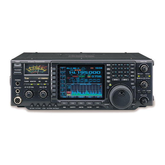
Icom IC-756PRO Alignment Procedure
Hide thumbs
Also See for IC-756PRO:
- Instruction manual (84 pages) ,
- Service manual (93 pages) ,
- Service manual (104 pages)
Advertisement
Quick Links
I C - 7 5 6 P R O A l i g n m e n t P r o c e d u r e
P L L B o a r d
Reference Oscillator
- Connect Frequency counter to P81 on the PLL board
- Adjust L53 and R33 for 64.000000MHz
- Connect RF volt meter to P81 on the PLL board
- Adjust L81 and L82 for maximum level
-
LPL A
- Set display to 0.0300000MHz, LSB
- Connect multi-meter to check point LPA
- Adjust C154 for 2.0V
VCO A
- Connect multi-meter to check point LVA
- Set display to 7.999999MHz, USB
- Adjust C278 for 4.3V
- Set display to 19.999999MHz, USB
- Adjust C258 for 4.3V
- Set display to 44.999999MHz, USB
- Adjust C228 for 4.3V
- Set display to 60.000000MHz, USB
- Adjust C208 for 4.3V
Advertisement

Related Manuals for Icom IC-756PRO


Summary of Contents for Icom IC-756PRO
- Page 1 I C - 7 5 6 P R O A l i g n m e n t P r o c e d u r e P L L B o a r d Reference Oscillator - Connect Frequency counter to P81 on the PLL board - Adjust L53 and R33 for 64.000000MHz - Connect RF volt meter to P81 on the PLL board - Adjust L81 and L82 for maximum level...
- Page 2 1LOA - Connect RF volt meter to P351 - Set display to 0.030000MHz - Verify RF output level for 0dBm or higher - Set display to 7.999999MHz - Verify RF output level for 0dBm or higher - Set display to 8.000000MHz - Verify RF output level for 0dBm or higher - Set display to 19.999999MHz - Verify RF output level for 0dBm or higher...
- Page 3 1LOA - Connect RF volt meter to P651 - Set display to 0.030000MHz - Verify RF output level for 0dBm or higher - Set display to 7.999999MHz - Verify RF output level for 0dBm or higher - Set display to 8.000000MHz - Verify RF output level for 0dBm or higher - Set display to 19.999999MHz - Verify RF output level for 0dBm or higher...
- Page 4 P A B o a r d Driver idling current - Set the mode to CW - Open W29 leads, and connect current meter - Transmit - Adjust R11 for 100mA - Close W29 Final idling current - Set the mode to CW - Open L8 side of R28 leads, and connect current meter - Transmit - Adjust R18 for 500mA...
- Page 5 M a i n B o a r d Initial setup for alignment - Reset the microprocessor (Hold “F-INP” and “M-CL” buttons and turning radio on) - Setup the radio as below - Frequency: 14.100000MHz - Filter: 2.4KHz - Mode: - Pre-amp: P.AMP1 - Antenna:...
- Page 6 Transmit Total Gain - Connect RF power meter to ANT connector - Connect AF signal generator to mic connector - Apply 1.5KHz/1mV signals to mic connector - Set MIC GAIN pot on the front panel to center - Adjust R263 for 50W IC APC - Connect RF power meter to ANT connector - Set radio to 3.550000MHz, RTTY...
- Page 7 FM transmit modulation - Set Radio to follows - Frequency: 29.60000MHz - Mode: - Filter: 15KHz - RF POWER: Maximum - Mic Gain: Center - Connect Modulation analyzer to ANT connector - Connect AF signal generator to mic connector - Apply 1KHz/10mV signals to mic connector - Transmit - Adjust R2227 on DSP board for 4.5KHz - Apply 1KHz/1mV signals to mic connector...
- Page 8 RX Receiver - Set radio to follows - Frequency: 14.1015MHz - Mode: - Shift: - Filter 2.4KHz - Connect RF signal generator to ANT connector - Connect SINARDER to external SP Jack - Receive - Adjust L111, L112 and L113 for maximum level RX Total Gain - Set radio to follows - Frequency:...
- Page 9 Noise Blanker - Set radio to follows - Frequency: 14.1015MHz - P AMP: - NB: - Mode: - Shift: - Filter 2.4KHz - Set R271 to center - Connect noise generator to ANT connector - Connect oscilloscope to CP271 - Apply noise signals to ANT connector - Adjust L272 for maximum level - Turns noise blanker on - Apply 20dBu noise signals to ANT connector...
- Page 10 R F b o a r d - Setup the radio as below - Frequency: 14.100000MHz - Mode: - Attenuater: - Dual watch: - RF/SQL: Center - RF Power: Maximum - R863: Center - R872: Center Transmitter - Connect RF power meter to ANT connector - Connect AF signal generator to mic connector - Connect RF volt meter to J151 - Apply 1.5KHz/1mV signals to mic connector...
- Page 11 Receiver - Set radio to follows - Frequency: 14.1015MHz - P AMP: - Mode: - Shift: - Filter 2.4KHz - Connect RF signal generator to ANT connector - Connect SINARDER to external SP Jack - Apply 14.1015MHz signals to ANT connector - Adjust L513, L721, L722 and L943 for maximum audio output - Set radio to follows - Dual watch:...
- Page 12 FM Distortion - Set radio to follows - Main Frequency: 14.1000000MHz - Sub Frequency: 14.1000000MHz - Mode: - Connect RF signal generator to ANT connector - Connect AF audio meter to external SP jack - Apply 14.1000000MHz/54dBu with 1KHz/3.5KHz deviation to ANT connector - Set balance controller to MAIN maximum - Adjust C555 for minimum audio output - Set balance controller to Sub maximum...
- Page 13 T u n e r B o a r d - Connect RF power meter - Connect multi-meter to J14 - Set 29.7MHz, RTTY - Ground J12 on the CTRL board - Turn on the tuner - Transmit - Adjust C3 for minimum voltage - Insert jumper plug to REMOTE jack - Turn off the radio - Hold both SSB and CW buttons, and turns radio back on (The radio should show “Setup Start menu”)