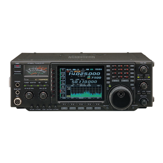
Icom IC-756PROII Service Manual
Hf/50mhz all mode transceiver
Hide thumbs
Also See for IC-756PROII:
- Instruction manual (88 pages) ,
- Service manual (119 pages) ,
- Instruction manual (88 pages)
Table of Contents
Advertisement
Advertisement
Table of Contents

Related Manuals for Icom IC-756PROII


Summary of Contents for Icom IC-756PROII
- Page 1 SERVICE MANUAL HF/50MHz ALL MODE TRANSCEIVER i756PRO ™...
- Page 2 1110000960 S.IC NJM4558M IC-756PROII MAIN-A UNIT 5 pieces 6. DO NOT transmit power into a signal generator or a 8810005770 Screw BiH M3×8 ZK IC-756PROII Top cover 10 pieces sweep generator. Addresses are provided on the inside back cover for your 7.
-
Page 3: Table Of Contents
TABLE OF CONTENTS SECTION 1 SPECIFICATIONS SECTION 2 INSIDE VIEWS SECTION 3 CIRCUIT DESCRIPTION 3 - 1 RECEIVER CIRCUITS ............3 - 1 3 - 2 TRANSMITTER CIRCUITS . -
Page 4: Specifications
SECTION 1 SPECIFICATIONS GENERAL RECEIVER • Frequency coverage: • Receive system : Triple-conversion superheterodyne Receive 0.030–60.000 MHz* • Intermediate frequencies: Transmit 1.800–1.999 MHz* 3.500–3.999 MHz* 1st IF frequency 64.455 MHz 7.000–7.300 MHz* 10.100–10.150 MHz* 2nd IF frequency 455 kHz 14.000–14.350 MHz* 18.068–18.168 MHz* 3rd IF frequency 36 kHz... -
Page 5: Inside Views
SECTION 2 INSIDE VIEWS • TOP VIEW 2 - 1... - Page 6 • BOTTOM VIEW 2 - 2...
-
Page 7: Circuit Description
SECTION 3 CIRCUIT DESCRIPTION • Used RF filter 3-1 RECEIVER CIRCUITS Control Input Control Input 3-1-1 RF SWITCHING CIRCUIT Band Band signal diode signal diode (CTRL AND RF-A UNITS) 0.03–1.6 MHz 11–15 MHz D281 The RF switching circuit leads receive signals to bandpass 1.6–2 MHz *D2001 15–22 MHz... - Page 8 3-1-5 1ST IF CIRCUIT (RF-A UNIT) Some DC voltage from the noise detector circuit is fed back to the noise amplifiers (Q271–Q273) via the DC amplifiers The 1st IF circuit filters and amplifies the 1st IF signal. The (Q274, Q275). The DC amplifiers function as an AGC circuit 1st IF signal combined at L653 is applied to a pair of MCF to reduce average noise.
- Page 9 The level shifted signal is applied to the DSP IC (IC2001) for 3-1-13 S-METER CIRCUIT (MAIN-A UNIT) 36 kHz digital IF filter, demodulation, automatic notch and The S-meter circuit indicates the relative received signal noise reduction, etc. The output signal is level shifted 3.3 V strength while receiving by utilizing the AGC voltage which to 5V at the level converter (IC2052), and is applied to the changes depending on the received signal strength.
-
Page 10: Transmitter Circuits
3-2 TRANSMITTER CIRCUITS The filtered signals are then applied to the differential ampli- fiers (IC2301a/b) via the analog switch (IC2201) and T/R 3-2-1 MICROPHONE AMPLIFIER CIRCUIT switch (IC2291). (MAIN-A UNIT) The microphone amplifier circuit amplifies microphone audio (2) When FM/AM modes signals to a level needed for the DSP circuit. - Page 11 3-2-5 IF AMPLIFIER AND MIXER CIRCUITS sequence to obtain a stable 100 W of RF output power. The amplified signal is applied to one of 8 low-pass filters in the (MAIN-A AND RF-A UNITS) FILTER unit. The modulated 3rd IF signal from the DSP-A board (DTIF: 36 kHz) is applied to the 3rd mixer circuit (MAIN-A unit;...
-
Page 12: Pll Circuits
The ALC bias voltage is also applied to the ALC meter ampli- 3-2-11 MONITOR CIRCUIT fier (IC551a, pin 2) to obtain an ALC meter signal (ALCL). (DSP-A BOARD AND MAIN-A UNIT) The amplified signal is passed through the analog switch (IC The microphone audio signals can be monitored to check 3631, pins 13, 14) and applied to the main CPU (IC3501, pin voice characteristics. - Page 13 (2) MAIN LOOP PLL doubler circuit (Q71, Q81) and the 64.0 MHz frequency is The oscillated signal at one of the main loop VCOs (Q201, picked up at the double tuned filter (L81, L82). The 64.0 D201, D202), (Q221, D221, D222), (Q251, D251–D254) and MHz signal is applied to the RF-A unit as a 2nd LO signal.
-
Page 14: Antenna Tuner Circuits
3-4 ANTENNA TUNER CIRCUITS (3) Tuning relays (TUNER unit) According to the operating frequency band and antenna 3-4-1 MATCHING CIRCUIT (TUNER UNIT) condition, tuning relays select the capacitors and coils. The matching circuit is a T-network. Using 2 tuning motors, the matching circuit obtains rapid overall tuning speed. -
Page 15: Scope Circuit
3-5 SCOPE CIRCUITS 3-6 POWER SUPPLY CIRCUITS 3-5-1 SCOPE RECEIVER CIRCUIT (RF-A UNIT) 3-6-1 PA UNIT A portion of the 64.455 MHz 1st IF signal from the 1st mixer LINE DESCRIPTION circuit (Q511–Q514: while receiving) or IF amplifier (Q751: The voltage from an external power supply via while transmitting) is passed through the PIN attenuator the common filter circuit (FILTER unit;... -
Page 16: Logic Circuits
3-6-3 MAIN-A UNIT 3-7-2 SUB-CPU PORT ALLOCATIONS (DISPLAY BOARD; IC401) LINE DESCRIPTION Port Receive 8 V converted from the 14 V line and Description number name regulated by the R8V regulator circuit (Q601, OSC1, Input and output ports for the system Q602, D601). - Page 17 3-7-3 MAIN-CPU PORT ALLOCATIONS (MAIN UNIT; IC3501) Port Port Description Description number name number name A0–A3, CON1 Outputs data signal for the DDS cir- 6–9, Address signal output ports for the 11–18, A4–A11, (PDAT) cuits (PLL unit; IC101, IC401). LCD controller (IC3551). 20–26 A12–A18 CON0...
- Page 18 3-7-4 INPUT EXPANDER ALLOCATIONS (1) DISPLAY board; IC411 (2) PLL unit; IC101 Port Port Description Description number name number name Input port for the [RIT], [∆TX] and Outputs the marker mute switch (IC192) [CLEAR] switches. control signal. MAKS High : When the [MARKER] is ON and Input port for [UP] and [DN] switches receiving.
- Page 19 (4) CTRL board; IC11 (6) RF-A unit; IC902 Port Port Description Description number name number name Outputs a low-pass filter select signal. Outputs a low-pass filter select signal. High: When 0.03–1.999999 High: When 11–13.999999 MHz or B7WS band is selected. 14.5–14.999999 MHz band is selected.
- Page 20 (8) MAIN-A unit; IC3653 (10) MAIN-A unit; IC3752 Port Port Description Description number name number name Outputs strobe signals for the output Outputs control signal for the noise BSTB expander ICs (RF-A unit; IC901, blanker switch (Q3751, Q3752). IC902, IC905). High: When the [NB] switch is ON, except in FM mode.
-
Page 21: Adjustment Procedures
SECTION 4 ADJUSTMENT PROCEDURES 4-1 PREPARATION BEFORE SARVICING REQUIRED TEST EQUIPMENT EQUIPMENT GREDE AND RANGE EQUIPMENT GREDE AND RENGE Output voltage : 13.8 V DC Frequency range : 300–3000 Hz DC power supply Audio generator Current capacity : 30 A or more Measuring range : 1–500 mV Measuring range... -
Page 22: Pll Adjustment
4-2 PLL ADJUSTMENTS ADJUSTMENT MEASUREMENT POINT ADJUSTMENT ADJUSTMENT CONDITION VALUE UNIT LOCATION UNIT ADJUST • Display frequency: Any Connect a frequency 64.000000 MHz REFERENCE (R33 FREQUENCY • Turn L52 on the PLL unit to 4 rota- counter to the check for critical adjustment) tion downside for presetting. - Page 23 PLL ADJUSTMENTS—continued ADJUSTMENT MEASUREMENT POINT ADJUSTMENT ADJUSTMENT CONDITION VALUE UNIT LOCATION UNIT ADJUST S2LO • Display frequency: Any Connect an RF volt- –3 dBm or more Verify OUTPUT • Receiving meter to the check point P901. LEVEL MARKER • Display frequency: Any Connect an oscillo- 4 Vp-p or more Verify...
- Page 24 4-3 TRANSMITTER ADJUSTMENTS ADJUSTMENT MEASUREMENT POINT ADJUSTMENT ADJUSTMENT CONDITION VALUE UNIT LOCATION UNIT ADJUST • Display frequency: 14.100000 MHz Unsolder W29. 100 mA IDLING CURRENT • Mode : CW (key up) Connect an ammeter (for driver) • Preset R11, R18 on the PA unit to to the unsoldering max.
-
Page 25: Transmitter Adjustment
• PA unit PA unit Ammeter Top view of the transceiver Idling current check point for drivers Unsoldering here Ammeter Idling current adjustment for finals Idling current adjustment for drivers Unsoldering here Idling current check point for finals • MAIN-A unit R263 Transmitter MAIN-A... - Page 26 TRANSMITTER ADJUSTMENTS—continued ADJUSTMENT MEASUREMENT POINT ADJUSTMENT ADJUSTMENT CONDITION VALUE UNIT LOCATION UNIT ADJUST Ic APC • Display frequency: 3.550000 MHz Rear Connect an ammeter 23 A MAIN-A R545 • Mode : RTTY panel between power sup- • Connect CP501 to GND. ™...
- Page 27 • MAIN-A unit MAIN-A unit Bottom view of the transceiver R509 50 MHz band output power adjustment CP501 Ic APC check point R510 AM carrier R507 adjustment HF bands output power adjustment R545 Ic APC adjustment • DSP-A board DSP-A board MAIN-A unit R2227...
-
Page 28: Receiver Adjustment
4-4 RECEIVER ADJUSTMENTS ADJUSTMENT MEASUREMENT POINT ADJUSTMENT ADJUSTMENT CONDITION VALUE UNIT LOCATION UNIT ADJUST RX PEAK • Display frequency: 14.100000 MHz Rear Connect an AC milli- Maximum audio output RF-A L513, • [DUAL WATCH] : OFF panel volt meter to [EXT level C555 •... - Page 29 • RF-A unit RF-A unit L513 Bottom view of the transceiver L613 RX peak adjustment C555 R515 C655 R516 Mixer balance L721 adjustment FM distortion R615 adjustment L713 R616 J711 Mixer ballance check point • MAIN-A unit MAIN-A unit Bottom view of the transceiver L111 L112 RX peak...
- Page 30 RECEIVER ADJUSTMENTS—continued ADJUSTMENT MEASUREMENT POINT ADJUSTMENT ADJUSTMENT CONDITION VALUE UNIT LOCATION UNIT ADJUST RECEIVER • Display frequency: 14.100000 MHz MAIN-A Connect an oscillo- 3.7 Vp-p MAIN-A R210 TOTAL GAIN • [DUAL WATCH] : OFF scope to the check • Mode : USB point CP213.
- Page 31 • MAIN-A unit MAIN-A unit Bottom view of the transceiver L273 Noise L272 blanker L271 adjustment R271 R210 Receiver total gain CP271 adjustment Noise blanker check point CP213 Receiver total gain check point • RF-A unit RF-A unit J841 Spectrum scope pre-setting Bottom view of the transceiver CP871...
-
Page 32: Tuner Adjustment
4-5 TUNER ADJUSTMENT ADJUSTMENT MEASUREMENT POINT ADJUSTMENT ADJUSTMENT CONDITION VALUE UNIT LOCATION UNIT ADJUST 1 • Display frequency: 29.70000 MHz CTRL Connect digital Minimum voltage CTRL DETECTOR • Mode : FM multimeter or oscillo- • [RF POWER] : Max. CW scope to the check •... -
Page 33: Meter Adjustment
4-6 METER ADJUSTMENT ADJUSTMENT ADJUSTMENT CONDITION DISPLAY OPERATION ENTERING • Enter the adjustment mode: ADJUST MODE Push [F-1 (METER)], [F-2 (TX)] or [F-3 (RX)] to ADJUSTMENT q Turn power OFF. select each adjustment mode. w Terminate the [REMOTE] jack MODE Once enterring adjustment mode, use [F-1 ( )] with a 3.5(d) mm mini-plug. - Page 34 METER ADJUSTMENT—continued ADJUSTMENT ADJUSTMENT CONDITION DISPLAY OPERATION (50M POWER -- TX -- Set the output power to 10 W using [MAIN METER) DIAL]. Then push [F-5 (SET)] to store the POWER 50M Tuner “POWER 50M Tuner” meter into memory, and to step next.
-
Page 35: Parts List
SECTION 5 PARTS LIST [FRONT UNIT] [DISPALY BOARD] ORDER ORDER DESCRIPTION DESCRIPTION 5080000450 LAMP SLU2LC1EX5B-TH D421 1750000520 S.DIODE DAN222TL D422 1750000520 S.DIODE DAN222TL D423 1750000520 S.DIODE DAN222TL 5510000490 METER ME-41 (KL-293S-11) SX2495 D424 1750000520 S.DIODE DAN222TL D425 1750000520 S.DIODE DAN222TL D431 1750000520 S.DIODE DAN222TL... - Page 36 [DISPLAY BOARD] [DISPLAY BOARD] ORDER ORDER DESCRIPTION DESCRIPTION R227 7030003440 S.RESISTOR ERJ3GEYJ 102 V (1 kΩ) R541 7030003560 S.RESISTOR ERJ3GEYJ 103 V (10 kΩ) ERJ3GEYJ 100 V (10 Ω) R228 7030003440 S.RESISTOR ERJ3GEYJ 102 V (1 kΩ) R544 7030003200 S.RESISTOR R229 7030003440 S.RESISTOR ERJ3GEYJ 102 V (1 kΩ)
- Page 37 [DISPLAY BOARD] [DISPLAY BOARD] ORDER ORDER DESCRIPTION DESCRIPTION R1212 7030003450 S.RESISTOR ERJ3GEYJ 122 V (1.2 kΩ) C830 4510006650 S.ELECTROLYTIC ECEV1EA100SR R1213 7030003490 S.RESISTOR ERJ3GEYJ 272 V (2.7 kΩ) C841 4510006240 S.ELECTROLYTIC ECEV1CA221P ERJ3GEYJ 151 V (150 Ω) R1221 7030003340 S.RESISTOR C842 4030011600 S.CERAMIC C1608 JB 1C 104KT-N...
-
Page 38: Phone Board
[DISPLAY BOARD] [PHONE BOARD] ORDER ORDER DESCRIPTION DESCRIPTION S621 2260001890 S.SWITCH SKQDPA 6200003950 S.COIL HF50ACC 322513-T S622 2260001890 S.SWITCH SKQDPA 6200003950 S.COIL HF50ACC 322513-T S623 2260001890 S.SWITCH SKQDPA S624 2260001890 S.SWITCH SKQDPA ERJ12YJ181U (180 Ω) S625 2260001890 S.SWITCH SKQDPA 7030006240 S.RESISTOR ERJ12YJ181U (180 Ω) S626 2260001890 S.SWITCH... -
Page 39: Key Board
[TEN-KEY BOARD] [KEY BOARD] ORDER ORDER DESCRIPTION DESCRIPTION 1590002310 S.TRANSISTOR DTC114EE TL 4030006880 S.CERAMIC C1608 JB 1H 472K-T-A 1590002310 S.TRANSISTOR DTC114EE TL 4030006880 S.CERAMIC C1608 JB 1H 472K-T-A 1590002310 S.TRANSISTOR DTC114EE TL 1590002310 S.TRANSISTOR DTC114EE TL 1590002310 S.TRANSISTOR DTC114EE TL 6510022620 S.CONNECTOR 10FMN-BMTTR-A-TBT 6450001790 CONNECTOR... - Page 40 [PLL UNIT] [PLL UNIT] ORDER ORDER DESCRIPTION DESCRIPTION Q651 1590001870 S.TRANSISTOR DTA114EE TL L128 6200001830 S.COIL NL 322522T-100J Q661 1590002310 S.TRANSISTOR DTC114EE TL L152 6130002970 COIL LB-343 Q681 1510000510 S.TRANSISTOR 2SA1576A T106R L153 6200001830 S.COIL NL 322522T-100J Q701 1530002060 S.TRANSISTOR 2SC4081 T107 R L181 6200001830 S.COIL...
- Page 41 [PLL UNIT] [PLL UNIT] ORDER ORDER DESCRIPTION DESCRIPTION ERJ3GEYJ 471 V (470 Ω) L901 6200008940 S.COIL LQH 3N 331K 34 R125 7030003400 S.RESISTOR L902 6200004950 S.COIL NL 252018T-1R8J R127 7030003800 S.RESISTOR ERJ3GEYJ 105 V (1 MΩ) ERJ3GEYJ 100 V (10 Ω) L903 6200003260 S.COIL NL 322522T-101J...
- Page 42 [PLL UNIT] [PLL UNIT] ORDER ORDER DESCRIPTION DESCRIPTION R409 7030005390 S.RESISTOR RR0816P-102-D (1 kΩ) R680 7030003560 S.RESISTOR ERJ3GEYJ 103 V (10 kΩ) ERJ3GEYJ 101 V (100 Ω) R410 7030005400 S.RESISTOR RR0816P-202-D (2 kΩ) R681 7030003320 S.RESISTOR R411 7030005390 S.RESISTOR RR0816P-102-D (1 kΩ) R685 7030003440 S.RESISTOR ERJ3GEYJ 102 V (1 kΩ)
- Page 43 [PLL UNIT] [PLL UNIT] ORDER ORDER DESCRIPTION DESCRIPTION R918 7030003680 S.RESISTOR ERJ3GEYJ 104 V (100 kΩ) C154 4610001850 S.TRIMMER TZBX4R200BA110T00 20P R919 7030003440 S.RESISTOR ERJ3GEYJ 102 V (1 kΩ) C155 4030016550 S.CERAMIC CM105 CH 151G 50AT ERJ3GEYJ 470 V (47 Ω) R920 7030003280 S.RESISTOR C156...
- Page 44 [PLL UNIT] [PLL UNIT] ORDER ORDER DESCRIPTION DESCRIPTION C363 4030006880 S.CERAMIC C1608 JB 1H 472K-T-A C506 4030009510 S.CERAMIC C1608 CH 1H 010B-T-A C364 4030006880 S.CERAMIC C1608 JB 1H 472K-T-A C507 4030006880 S.CERAMIC C1608 JB 1H 472K-T-A C365 4030011600 S.CERAMIC C1608 JB 1C 104KT-N C508 4610001860 S.TRIMMER TZBX4Z060BA110T00 6P...
- Page 45 [PLL UNIT] [PLL UNIT] ORDER ORDER DESCRIPTION DESCRIPTION C708 4030006880 S.CERAMIC C1608 JB 1H 472K-T-A W170 7030008240 S.JUMPER ERJ12YJ0R00U C709 4030011340 S.CERAMIC C1608 CH 1H 471J-T-A W181 7030003860 S.JUMPER ERJ3GE JPW V C710 4030007120 S.CERAMIC C1608 CH 1H 820J-T-A W201 7030003970 S.JUMPER MCR18EZHJ JPW C711...
- Page 46 [PA UNIT] [PA UNIT] ORDER ORDER DESCRIPTION DESCRIPTION 6140003240 S.COIL LR-361 4510004630 S.ELECTROLYTIC ECEV1CA100SR 2040000490 COIL EXC-ELDR25C 4030008920 S.CERAMIC C1608 JB 1C 473K-T-A 2040000490 COIL EXC-ELDR25C 4030008920 S.CERAMIC C1608 JB 1C 473K-T-A 6140001180 COIL LR-143 4030011600 S.CERAMIC C1608 JB 1C 104KT-N 2040000490 COIL EXC-ELDR25C 4030012620 S.CERAMIC...
- Page 47 [PA UNIT] [TUNER UNIT] ORDER ORDER DESCRIPTION DESCRIPTION 9045201001 WIRE 74/98/040/X98/X98 4030006880 S.CERAMIC C1608 JB 1H 472K-T-A 9021780060 WIRE 74/98/018/X98/X98 4030006880 S.CERAMIC C1608 JB 1H 472K-T-A 9021780060 WIRE 74/98/018/X98/X98 4030006880 S.CERAMIC C1608 JB 1H 472K-T-A 4030006880 S.CERAMIC C1608 JB 1H 472K-T-A 4030006880 S.CERAMIC C1608 JB 1H 472K-T-A 8970023490 CABLE...
- Page 48 [FILTER UNIT] [FILTER UNIT] ORDER ORDER DESCRIPTION DESCRIPTION 6140002570 COIL LR-294 (T50-2) 4010005390 CERAMIC HM15SJ SL 621J 500V 6140002580 COIL LR-295 (T50-2) 4010005390 CERAMIC HM15SJ SL 621J 500V 6140001240 COIL LR-149 (T68-2) 4030011210 S.CERAMIC GRM42-6 CH 330J 500PT 6140001130 COIL LR-138 (T68-2) 4030011240 S.CERAMIC GRM42-6 CH 470J 500PT...
- Page 49 [FILTER UNIT] [CTRL UNIT] ORDER ORDER DESCRIPTION DESCRIPTION 7030003860 S.JUMPER ERJ3GE JPW V 6140003270 COIL LR-364 8900009620 CABLE OPC-961 6200001830 S.COIL NL 322522T-100J 8900009630 CABLE OPC-962 6200003260 S.COIL NL 322522T-101J 6140003270 COIL LR-364 6180001220 COIL LAL 04NA 100K 0910051805 PCB B 5287E 6140003270 COIL LR-364...
- Page 50 [CTRL UNIT] [CTRL UNIT] ORDER ORDER DESCRIPTION DESCRIPTION 7030003440 S.RESISTOR ERJ3GEYJ 102 V (1 kΩ) 4010005530 CERAMIC HM60SJ SL 020C 500V ERJ3GEYJ 101 V (100 Ω) 7030003320 S.RESISTOR 4030011540 S.CERAMIC C1608 CH 1H 750J-T-A 7030003440 S.RESISTOR ERJ3GEYJ 102 V (1 kΩ) 4030006860 S.CERAMIC C1608 JB 1H 102K-T-A 7030003560 S.RESISTOR...
-
Page 51: Memory Board
[CTRL UNIT] [RF-A UNIT] ORDER ORDER DESCRIPTION DESCRIPTION 4030006880 S.CERAMIC C1608 JB 1H 472K-T-A IC151 1110001890 S.IC µPC1678G-E2 4510006220 S.ELECTROLYTIC ECEV1CA101UP IC451 1110003970 S.IC µPC1658G-E1 C100 4030011570 S.CERAMIC CM105 CH 101G 50AT IC841 1110003490 S.IC TA31136FN (D, EL) C101 4030006880 S.CERAMIC C1608 JB 1H 472K-T-A IC871 1110000960 S.IC... - Page 52 [RF-A UNIT] [RF-A UNIT] ORDER ORDER DESCRIPTION DESCRIPTION D443 1790000620 S.DIODE MA77 (TX) L343 6200003010 S.COIL NL 322522T-R27J-3 D444 1790000620 S.DIODE MA77 (TX) L361 6200008100 S.COIL LQN 1H R14J04 D481 1790000620 S.DIODE MA77 (TX) L363 6200007810 S.COIL LQN 1H 95NK04 D531 1750000450 S.DIODE 1SV265-TL...
- Page 53 [RF-A UNIT] [RF-A UNIT] ORDER ORDER DESCRIPTION DESCRIPTION ERJ3GEYJ 221 V (220 Ω) L812 6150004280 COIL LS-484B (C-14927) R531 7030003360 S.RESISTOR L813 6150004280 COIL LS-484B (C-14927) R532 7030003460 S.RESISTOR ERJ3GEYJ 152 V (1.5 kΩ) L831 6140003210 S.COIL LR-358 R533 7030003440 S.RESISTOR ERJ3GEYJ 102 V (1 kΩ) L832 6140003210 S.COIL...
- Page 54 [RF-A UNIT] [RF-A UNIT] ORDER ORDER DESCRIPTION DESCRIPTION R807 7030003440 S.RESISTOR ERJ3GEYJ 102 V (1 kΩ) C131 4030011600 S.CERAMIC C1608 JB 1C 104KT-N R808 7030003440 S.RESISTOR ERJ3GEYJ 102 V (1 kΩ) C132 4030011600 S.CERAMIC C1608 JB 1C 104KT-N R811 7030003520 S.RESISTOR ERJ3GEYJ 472 V (4.7 kΩ) C133 4030011600 S.CERAMIC...
- Page 55 [RF-A UNIT] [RF-A UNIT] ORDER ORDER DESCRIPTION DESCRIPTION C329 4030006980 S.CERAMIC C1608 CH 1H 070D-T-A C603 4030007080 S.CERAMIC C1608 CH 1H 390J-T-A C330 4030007050 S.CERAMIC C1608 CH 1H 220J-T-A C604 4030007030 S.CERAMIC C1608 CH 1H 150J-T-A C332 4030007050 S.CERAMIC C1608 CH 1H 220J-T-A C605 4030007100 S.CERAMIC C1608 CH 1H 560J-T-A...
- Page 56 [RF-A UNIT] [RF-A UNIT] ORDER ORDER DESCRIPTION DESCRIPTION C772 4030006880 S.CERAMIC C1608 JB 1H 472K-T-A J561 6510007020 CONNECTOR TMP-J01X-V6 C774 4030009920 S.CERAMIC C1608 CH 1H 050B-T-A J661 6510007020 CONNECTOR TMP-J01X-V6 C775 4030007040 S.CERAMIC C1608 CH 1H 180J-T-A J711 6510007020 CONNECTOR TMP-J01X-V6 C781 4030011600 S.CERAMIC...
- Page 57 [BPF BOARD] [MAIN-A UNIT] ORDER ORDER DESCRIPTION DESCRIPTION C2004 4030010760 S.CERAMIC C1608 CH 1H 331J-T-A IC101 1110000960 S.IC NJM4558M-T1 C2005 4030007140 S.CERAMIC C1608 CH 1H 121J-T-A IC151 1130006220 S.IC TC4W53FU (TE12L) C2006 4030007160 S.CERAMIC C1608 CH 1H 181J-T-A IC152 1130003610 S.IC TC4SU69F (TE85R) C2007 4030007060 S.CERAMIC C1608 CH 1H 270J-T-A...
- Page 58 [MAIN-A UNIT] [MAIN-A UNIT] ORDER ORDER DESCRIPTION DESCRIPTION Q652 1540000440 S.TRANSISTOR 2SD1619-T-TD FI111 2020000260 CERAMIC CFK455E10 Q653 1590001150 S.TRANSISTOR UN9211 (TX) FI131 2020001740 CERAMIC CFWM455D Q691 1590001150 S.TRANSISTOR UN9211 (TX) FI133 2020001510 CERAMIC CFWS455IT Q801 1530002060 S.TRANSISTOR 2SC4081 T107 R Q803 1590002430 S.TRANSISTOR DTA144EE TL...
- Page 59 [MAIN-A UNIT] [MAIN-A UNIT] ORDER ORDER DESCRIPTION DESCRIPTION R102 7030003730 S.RESISTOR ERJ3GEYJ 274 V (270 kΩ) R283 7030003640 S.RESISTOR ERJ3GEYJ 473 V (47 kΩ) R103 7030003680 S.RESISTOR ERJ3GEYJ 104 V (100 kΩ) R284 7030003640 S.RESISTOR ERJ3GEYJ 473 V (47 kΩ) R104 7030003620 S.RESISTOR ERJ3GEYJ 333 V (33 kΩ)
- Page 60 [MAIN-A UNIT] [MAIN-A UNIT] ORDER ORDER DESCRIPTION DESCRIPTION ERJ3GEYJ 221 V (220 Ω) R464 7030003640 S.RESISTOR ERJ3GEYJ 473 V (47 kΩ) R807 7030003360 S.RESISTOR R465 7030003640 S.RESISTOR ERJ3GEYJ 473 V (47 kΩ) R3003 7030003640 S.RESISTOR ERJ3GEYJ 473 V (47 kΩ) R466 7030003680 S.RESISTOR ERJ3GEYJ 104 V (100 kΩ)
- Page 61 [MAIN-A UNIT] [MAIN-A UNIT] ORDER ORDER DESCRIPTION DESCRIPTION R3555 7030003580 S.RESISTOR ERJ3GEYJ 153 V (15 kΩ) R3705 7030003800 S.RESISTOR ERJ3GEYJ 105 V (1 MΩ) R3556 7030003580 S.RESISTOR ERJ3GEYJ 153 V (15 kΩ) R3706 7030003440 S.RESISTOR ERJ3GEYJ 102 V (1 kΩ) R3557 7030003580 S.RESISTOR ERJ3GEYJ 153 V (15 kΩ) R3707 7030003440 S.RESISTOR...
- Page 62 [MAIN-A UNIT] [MAIN-A UNIT] ORDER ORDER DESCRIPTION DESCRIPTION C141 4030006860 S.CERAMIC C1608 JB 1H 102K-T-A C325 4030011600 S.CERAMIC C1608 JB 1C 104KT-N C142 4030011600 S.CERAMIC C1608 JB 1C 104KT-N C326 4030011600 S.CERAMIC C1608 JB 1C 104KT-N C144 4030011600 S.CERAMIC C1608 JB 1C 104KT-N C327 4030012600 S.CERAMIC C2012 JB 1A 105M-T-A...
- Page 63 [MAIN-A UNIT] [MAIN-A UNIT] ORDER ORDER DESCRIPTION DESCRIPTION C670 4030006880 S.CERAMIC C1608 JB 1H 472K-T-A C3502 4030007020 S.CERAMIC C1608 CH 1H 120J-T-A C681 4030006880 S.CERAMIC C1608 JB 1H 472K-T-A C3503 4030006900 S.CERAMIC C1608 JB 1E 103K-T-A C691 4030006880 S.CERAMIC C1608 JB 1H 472K-T-A C3504 4030006900 S.CERAMIC C1608 JB 1E 103K-T-A C692...
- Page 64 [MAIN-A UNIT] [MAIN-A UNIT] ORDER ORDER DESCRIPTION DESCRIPTION C3764 4030006880 S.CERAMIC C1608 JB 1H 472K-T-A 8970023940 SX2178 P352*J352 (1) /MA-A C3765 4030006880 S.CERAMIC C1608 JB 1H 472K-T-A C3766 4030006880 S.CERAMIC C1608 JB 1H 472K-T-A C3767 4030006880 S.CERAMIC C1608 JB 1H 472K-T-A 0910054303 PCB B 5705C C3768 4030006880 S.CERAMIC...
- Page 65 [DSP-A UNIT] [DSP-A UNIT] ORDER ORDER DESCRIPTION DESCRIPTION L2502 6200003950 S.COIL HF50ACC 322513-T R2283 7030003560 S.RESISTOR ERJ3GEYJ 103 V (10 kΩ) ERJ3GEYJ 101 V (100 Ω) L2503 6200003950 S.COIL HF50ACC 322513-T R2291 7030003320 S.RESISTOR ERJ3GEYJ 101 V (100 Ω) L2504 6200003950 S.COIL HF50ACC 322513-T R2292 7030003320 S.RESISTOR...
- Page 66 [DSP-A UNIT] [DSP-A UNIT] ORDER ORDER DESCRIPTION DESCRIPTION R2446 7030003560 S.RESISTOR ERJ3GEYJ 103 V (10 kΩ) C2030 4030011600 S.CERAMIC C1608 JB 1C 104KT-N R2447 7030003560 S.RESISTOR ERJ3GEYJ 103 V (10 kΩ) C2031 4030011600 S.CERAMIC C1608 JB 1C 104KT-N R2448 7030003560 S.RESISTOR ERJ3GEYJ 103 V (10 kΩ) C2033 4030012600 S.CERAMIC C2012 JB 1A 105M-T-A...
- Page 67 [DSP-A UNIT] [DSP-A UNIT] ORDER ORDER DESCRIPTION DESCRIPTION C2351 4030007010 S.CERAMIC C1608 CH 1H 100D-T-A C2515 4030006860 S.CERAMIC C1608 JB 1H 102K-T-A C2352 4030007010 S.CERAMIC C1608 CH 1H 100D-T-A C2519 4030006860 S.CERAMIC C1608 JB 1H 102K-T-A C2353 4510004630 S.ELECTROLYTIC ECEV1CA100SR C2520 4030006860 S.CERAMIC C1608 JB 1H 102K-T-A C2354 4030011600 S.CERAMIC...
-
Page 68: Mechanical Parts
SECTION 6 MECHANICAL PARTS [FRONT UNIT] [RIT BOARD] REF. NO. ORDER NO. DESCRIPTION QTY. REF. NO. ORDER NO. DESCRIPTION QTY. 2250000340 Encoder EVQ-VCJF0324B 5080000450 SLU2LC1EX5B-TH 5510000490 Meter ME-41 6910011090 Sensor unit RMS20-250-201-P 6450001230 Plate HLJ0999-01-480 6450001230 Plate HLJ0999-01-480 [PHONE BOARD] 6910012500 Unit board TFD50W40-A REF. - Page 69 PHONE BOARD MP1 (F) MP19 (F) MP5 (F) MP3 (F) MP12 (F) MP3 (DIS) MP23 (F) ME1 (F) MP7 (F) MP6 (F) MP11 (F) MP4 (DIS) J2 (PH) DISPLAY BOARD MP6 (DIS) W3 (F) MP1 (DIS) KEY BOARD MP4 (F) J2 (KE) MP51 (F) R701 (DIS)
- Page 70 MP46 (C) W13 (C) MP28 (C) MP53 (C) EP2 (C)+MP46 (C) MP61 (C) MP20 (C) MP16 (C) MP47 (C) MP46 (C) SP1 (C) PA UNIT MP31 (C) MP32 (C) FILTER UNIT MP79 (C) MP2 (C) MP34 (C) EP1 (C) MP63 (C) MP23 (C) MP72 (C) MP70 (C)
- Page 71 [CHASSIS PARTS] [MAIN-A UNIT] [PLL UNIT] [UNPACKING] REF. NO. ORDER NO. DESCRIPTION QTY. REF. NO. ORDER NO. DESCRIPTION QTY. REF. NO. ORDER NO. DESCRIPTION QTY. REF. NO. ORDER NO. DESCRIPTION QTY. Screw PH FT M3 × 6 5210000090 Fuse FGB 30A BT3501 3020000110 Lithium battery CR2032...
-
Page 72: Semi-Conductor Information
SECTION 7 SEMI-CONDUCTOR INFORMATION • TRANSISTORS AND FET’S 2SA1162 GR 2SA1576A T106 R 2SA1577 2SB1124 S TD 2SB1132 T100 R DTC144 EE TL DTC144 TE UMD3 N TL UMH4N TN UMH11N TN (Symbol: 26) (Symbol: 06) (Symbol: D3) (Symbol: H4) (Symbol: H11) (Symbol: SG) (Symbol: FR) - Page 73 • DIODES 1SS226 1SS301 1SS319 1SS322 1SS375-TL (Symbol: C3) (Symbol: B3) (Symbol: A4) (Symbol: A9) (Symbol: FH) 1SV263 TL 1SV265 TL 1SV307 1SV308 DA221 TL (Symbol: JV) (Symbol: LV) (Symbol: TX) (Symbol: TX) (Symbol: K) DAN222TL DAP222 TL DWA010 TE HSB88WSTR HSM88ASR TR (Symbol: N)
-
Page 74: Board Layouts
SECTION 8 BOARD LAYOUTS 8-1 PBT, RIT AND MIC BOARDS • PBT BOARD PBT1/PBT2 NOTCH/CW PITCH to DISPLAY board J601 • RIT BOARD • MIC BOARD to DISPLAY board J322 to DISPLAY board J120 8 - 1... -
Page 75: Display Board
8-2 DISPLAY BOARD (TOP VIEW) POWER TRANSMIT TUNER MONITOR AF, AF/SQL BAL/NR COMP BK-IN GAIN POWER DELAY SPEED 8 - 2... - Page 76 • DISPLAY BOARD (BOTTOM VIEW) J531 to MAIN-A unit J891 POLC J301 to LCD J601 VCOM NOTL J451 PITL J452 J801 PB1A PB1B to PBT PB2A to MAIN-A PB2B board J1 to LCD to SP unit J352 L18V SSPE -15V J941 to PHONE board J1...
-
Page 77: Mode, Phone, Key And Ten-Key Boards
8-3 MODE, PHONE, KEY AND TEN-KEY BOARDS • TEN-KEY BOARD (TOP VIEW) SPLIT • MODE BOARD (TOP VIEW) • PHONE BOARD DOWN PHNI CHANGE to DISPLAY GENE F-INP M-CL board J941 PBT-CL NOTCH MP-W MP-R • KEY BOARD DASH to DISPLAY board J921 ∆TX CLEAR... - Page 78 • TEN-KEY BOARD (BOTTOM VIEW) • MODE BOARD (BOTTOM VIEW) SPLK to DISPLAY board J221 GENK FINK MPWK MPRK MUPK MDNK MCLK XFCK LOCK PBTK NOTK to DISPLAY LOCD board J241 NOTD PBTD to DISPLAY board J201 8 - 5...
-
Page 79: Rf-A Unit
8-4 RF-A UNIT (TOP VIEW) XVRT RANT P901 S2LO from PLL unit J901 P801 S3LO from CTRL unit J2 from PLL unit J801 T/R2IF J203 to BPF board J201 BPFI BPFO to BPF board J202 to BPF J951 board TRVI SATV BLBV BLAV... - Page 80 • RF-A UNIT (BOTTOM VIEW) 8 - 7...
-
Page 81: Pll Unit
8-5 PLL UNIT (TOP VIEW) P851 to RF-A unit J481 1LOA UNLC PSEL CON2 to MAIN-A CON1 CON0 unit J841 DRES PSTB S3LO 1LOB P901 S2LO to RF-A unit J831 8 - 8... - Page 82 • PLL UNIT (BOTTOM VIEW) Soldering point 8 - 9...
-
Page 83: Main-A Unit
8-6 MAIN-A UNIT (TOP VIEW) P701 from PLL unit J701 J202 3R3V _ d AGRS 3R3V _ d M5V _ d NSQO DSDR DPGI UNSB MODS J352 FMNS CALS DSFW ACKS MDAT DSRS to DISPLAY DSFR board J451 CTFL RTDT MSL1 J641 DSKY... - Page 84 • MAIN-A UNIT (BOTTOM VIEW) 5 10 8 - 11...
-
Page 85: Dsp-A, Memory And Bpf Boards
8-7 DSP-A, MEMORY AND BPF BOARDS • DSP-A BOARD (TOP VIEW) • MEMORY BOARD (TOP VIEW) A10s A10f RESET BYTE BYTE BYTE to MAIN-A to MAIN-A unit J3504 unit J3503 • BPF BOARD (TOP VIEW) 8 - 12... - Page 86 • MEMORY BOARD (BOTTOM VIEW) • DSP-A BOARD (BOTTOM VIEW) • BPF BOARD (BOTTOM VIEW) BPFI BPFO J2001 J2002 to MAIN-A unit J201 to MAIN-A unit J202 8 - 13...
-
Page 87: Pa Unit
8-8 PA UNIT (TOP VIEW) to FILTER unit to FILTER unit to MAIN-A unit J771 8 - 14... - Page 88 • PA UNIT (BOTTOM VIEW) 8 - 15...
-
Page 89: Filter Unit
8-9 FILTER UNIT (TOP VIEW) to CTRL unit J13 CTIN to CHASSIS J4 from CTRL unit J1 to CHASSIS J4 to PA unit EP5 from PA unit J2 to PA unit EP4 8 - 16... - Page 90 • FILTER UNIT (BOTTOM VIEW) 8 - 17...
-
Page 91: Tuner Board
8-10 TUNER BOARD (TOP VIEW) to CTRL unit J8 TUIN to CTRL unit J3 TUOT to CTRL unit J4 8 - 18... - Page 92 • TUNER BOARD (BOTTOM VIEW) 8 - 19...
-
Page 93: Ctrl Unit
8-11 CTRL UNIT (TOP VIEW) from TUNER board J5 TUIN from TUNER board J3 RFRX to RF-A unit J101 T14V CHASSIS to MF2 T14V to MF1 CHASSIS CTIN TUOT from TUNER board J4 to FILTER unit J2 from FILTER from MAIN-A unit J741 unit J3 8 - 20... - Page 94 • CTRL UNIT (BOTTOM VIEW) 8 - 21...
- Page 95 SECTION 9 BLOCK DIAGRAM IC2041 RX ANT ANT2 ANT1 DSP-A BOARD MAIN-A UNIT Q445 XP4311 TC7SHU04FU IC2091 S-80934ANMP-DDY IC2301A Q722 D531,D532 1SV265 IC2042 Q2321 2SJ381 XP4311 Q501,Q502 IC2092 TC7S02FU BA15532F FI111 Q551 D533 1SV263 X2041 TC7SH04FU Q2322 2SJ381 D535 MA77 Q511-Q514 2SK2171 DRIVER...
-
Page 96: Front Unit
SECTION 10 VOLTAGE DIAGRAMS 10-1 FRONT UNIT FRONT J601 J301 CP101 LFMD R301 LFMD J101 LMFD +14V NOTL R601 NOTL NOTL R312 LMFD CP102 CP103 R3 47k IC101a IC101c PITL R602 PITL PITL SRES R313 SRES MAIN DIAL UP MAIN DIAL DOWN µPD4030BG µPD4030BG (PITCH) -
Page 97: Dsp-A Board
10-2 DSP-A BOARD J2002 C2515 0.001 C2519 0.001 M5V_d IC2291 TX 4.2V TX FM/AM/SSB:30mVp-p R2306 IC2301B TC4W53FU RX 0V C2281 R2304 R2309 BA15532F 0.47 R2302 C2301 R2308 C2308 IC2201 R2503 DSKY BU4053BCFV R2510 RTDT W2302 W2301 R2505 MSL1 RX 90dBµ input:200mVp-p IC2301A BA15532F R2242... -
Page 98: Tuner, Memory Boards And Ctrl Unit
10-3 TUNER, MEMORY BOARDS AND CTRL UNIT CTRL UNIT 100µH LR-307 LR-307 LR-363 LR-363 LR-490 LR-489 LR-490 LR-489 LR-490 MP28GA Q211 DTC114EU Q212 NY-12W-K NY-12W-K NY-12W-K NY-12W-K NY-12W-K NY-12W-K NY-12W-K DTC114EU Q213 T14V DTC114EU Q214 DTC114EU Q215 DTC114EU MP28GA HSM88AS Q216 10µH FILTER... -
Page 99: Main-A Unit (1)
10-4 MAIN-A UNIT (1) MAIN-A UNIT (1) W702 C158 J741 C702 BUS LINE1 R202 L701 EXC-ELDR25C L274 2.2k L271 L272 L273 CP271 CP272 C703 100mH IC151 LS-450 Q272 LS-450 Q273 LS-450 IC201a FI111 C704 Q271 Q279 C289 Q276 TC4W53FU L151 2SK882 2SK882 2SK882... -
Page 100: Main-A Unit (2)
10-5 MAIN-A UNIT (2) MAIN-A UNIT (2) BUS LINE1 J641 L3602 HF50ACC322513-B L3603 RCR-875D-472K M5V_ M5V_ L641 220µH ETKY L3601 HF50ACC322513-B H5V_ H5V_ START L642 220µH ETST 3R3V_d L3501 HF50ACC322513-B 3R3V_d L643 HF70ACC635050-T ET14 3R3V_d TUNER L644 HF70ACC635050-T –5V –5V UNLC UNLC_ R3601... -
Page 101: Pll Unit
10-6 PLL UNIT 4.8V 7.7V PLL UNIT L701 32MHz_REF 32MHz_REF 32MHz_REF UNLC ULPA 10µH R701 2k R702 1k P351 J351 ULPB to RF-A 1LOA unit J561 IC191 DRES R703 2k R704 1k TC7S08F DAP222 C192 R730 UMD3N R492 L491 L492 L205 MEASUREMENT CONDITIONS L505... -
Page 102: Pa And Filter Units
10-7 PA AND FILTER UNITS C61 0.001 CP11 CP12 C123 CP13 CP14 (CTRL) P1 RX 13.7V C22 0.001 RX 13.8V CTIN TX 13.6V TX 13.6V CTIN T14V C118 T14V RX 0V RX 0V C21 0.001 120p LA-548 LA-550 LA-547 LA-481 LA-480 FRONT CHASSIS W11... -
Page 103: Rf-A Unit And Bpf Board
10-8 RF-A UNIT AND BPF BOARD D181 MMBV3700LT1 L121 C131 J101 68nH R182 C181 L181 L182 D421 C491 6.8µH 6.8µH MA77 Q601 L666 L665 L664 L667 C664 R663 C661 from CTRL L601 L602 L603 C606 2SK2171 LR-358 68nH 68nH 68nH 0.001 unit J2 14VL... - Page 105 S-13807HZ-C1 © 2001 Icom Inc. 1-1-32, Kamiminami, Hirano-ku Osaka 547-0003, Japan...