
Related Manuals for Sanyo VCC-5974


Summary of Contents for Sanyo VCC-5974
- Page 1 VCC-5974 INSTRUCTION MANUAL COLOR CCD Camera About this manual Before installing and using the camera, please read this manual carefully. Be sure to • keep it handy for later reference.
- Page 2 OBLIGATIONS In order to obtain warranty service, the product must be delivered to and picked up from an Authorized Sanyo Service Center at the user’s expense, unless specifically stated otherwise in this warranty. The names and addresses of Authorized Sanyo Service Centers may be obtained by writing to SFS Corporation, SFC’s warranty administrator, at any of the addresses listed...
-
Page 3: Table Of Contents
Depending on the conditions of use, FEATURES installation and environment, please be sure to make the appropriate settings and • Built-in interline transfer method 1/3" CCD, adjustments. If you need help with installation approx. 410,000 picture elements and/or settings, please consult your dealer. •... -
Page 4: Information To User
(2) this device must accept any codes. interference received, including interference that may cause undesired operation. Changes or modifications not expressly approved by Sanyo may void the user’s authority to operate this camera. English... -
Page 5: Precautions
For Install where the temperature range will stay internal settings and repairs, consult your between –10˚C and 50˚C. dealer (or a Sanyo Authorized Service Centre). (no condensation) Do not put objects inside the unit Cleaning Make sure that no metal objects or flammable •... -
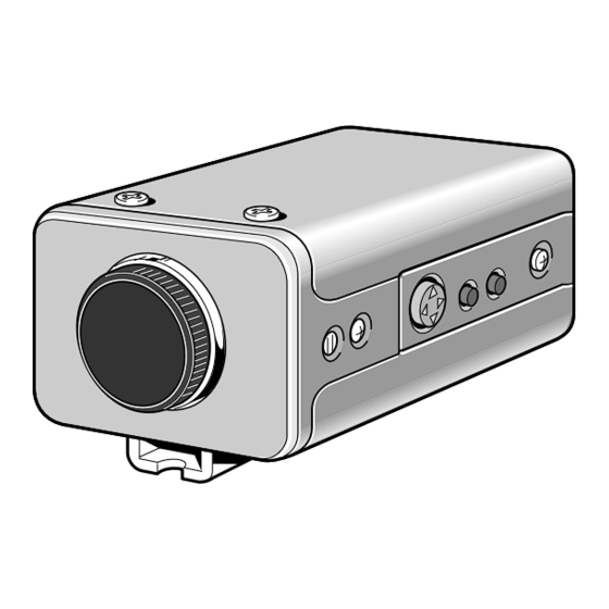
Page 6: Parts Names
PARTS NAMES Lens iris output connector (4 pin) This 4-pin connector is used to send the DC control signal and power supply to an auto-iris type lens. Auto white balance push lock button (AWB LOCK) Menu setting button (SET) Connect the camera to the monitor, then press the SET button for about 3 seconds to display the on-screen menu. - Page 7 PARTS NAMES Camera setup section (under the cover) This unit factory settings are as indicated below. These settings are for when using a 1/3 inch CS mount DC (without EE internal amplifier) type lens. However, if due to installation conditions or environment the settings may need to be modified for best results (see "SETTINGS").
- Page 8 24 V AC input terminal (24 V AC, GND) With this camera use only the 24 V AC power adaptor model No. VPT-115 available from Sanyo. Power supply connections Use a 3 wire grounded cable (22 AWG or more), and connect as G N D shown by the illustration.
-
Page 9: Mounting The Lens
PARTS NAMES Flange-back adjustment If the pick-up surface is not correctly positioned with relation to the lens focal point, the picture will be out of focus (in particular when using auto-iris power zoom lenses, sold separately). If that is the case, adjust the flange-back position as described below. Using a + screwdriver, loosen the FLANGE BACK LOCK screw (M2:+). - Page 10 MOUNTING THE LENS Installation of a VIDEO type auto-iris lens (sold separately) 2 (A) A 1/2 or 2/3 inch C mount type lens with EE amplifier circuit that uses the video signal and a DC power source. Remove the lens mount cap. Attach the supplied C mount adaptor (A) to the auto-iris lens (B), then install the assembly on the camera.
-
Page 11: Connections
MOUNTING THE LENS Compatible auto-iris lenses 1/3 inch Sanyo DC type lens 1/2 or 2/3 inch VIDEO type lens VCL-CS8LY: Standard angle, f= 8 mm Standard angle, f= 9 mm VCL-CS4LY: Wide angle, f= 4 mm Telephoto angle, f= 12 mm VCL-CS2LY: Ultra-wide angle, f= 2.8 mm... -
Page 12: Settings
SETTINGS The illustration shows the factory default settings for the switches in the camera setup section. Depending on the camera installation location and conditions of use, it may be necessary to select other settings, without having to make adjustments. The selected settings can be confirmed using the on-screen menu. - Page 13 SETTINGS Automatic Gain Control (AGC) setting The automatic gain control can be turned ON or OFF using the AGC ON/OFF switch (6) in the camera setup section. ON: Auto gain control function on (setting used under normal conditions) (see page 23). GAMMA: ON (0.45), OFF (1) AGC GAIN: NORMAL (30 dB), HIGH (36 dB) OFF: Fixed gain...
- Page 14 Backlight compensation (BLC) setting The backlight compensation ON/OFF is set using the BLC ON/OFF switch (9) in the camera setup section. ON: Default setting, backlight compensation function on. However, depending on the camera installation location and conditions of use, if the backlight compensation function need to be set, with the BLC switch set to ON, press the SET button to select one of PRESET (1, 2) or W0=1...
-
Page 15: Using The On-Screen Menus
USING THE ON-SCREEN MENUS (Menu 1) (Menu 2) MENU FOR ADJUSTMENT MENU FOR ADJUSTMENT CAMERA ID SYNC IRIS APERTURE WHITE BALANCE SHUTTER WRITE PROTECT WRITE PROTECT PREVIOUS PAGE NEXT PAGE To display the menu Press the SET button for about 3 seconds. The “MENU FOR ADJUSTMENT”... -
Page 16: Adjustments
ADJUSTMENTS To enter settings or adjustments for the camera it must be connected to a monitor. The settings and adjustments are made (Menu 1) by ways of on-screen displays. MENU FOR ADJUSTMENT SYNC Concerning the WRITE PROTECT function IRIS In order to protect the settings and adjustments the WRITE WHITE BALANCE PROTECT function is set to ON. -
Page 17: Sync
ADJUSTMENTS 1. SYNC 1-1. V sync phase adjustment When using a camera switcher to connect 2 cameras or more to one monitor, there may be a vertical roll of the images when switched. In such a case, set as described below. Set the SYNC switch (4) to L-L. -
Page 18: Vbs Phase Adjustment
1-2. VBS phase adjustment Connect a VBS signal source to the VBS IN connector on the camera. The on-screen setting will automatically switch to VBS. Press the CURSOR (j or l) button to select the on-screen VBS setting (get it flashing), then press the SET button. The adjustment sub-menu “ADJUSTMENT FOR VBS”... -
Page 19: Iris
ADJUSTMENTS 2. IRIS 2-1. Auto-iris level adjustment Set the IRIS switch (10) to AI. The on-screen setting will automatically switch to AI. Press the CURSOR (j or l) button to select the on-screen AI setting (get it flashing), then press the SET button. The adjustment sub-menu “ADJUSTMENT FOR AI”... -
Page 20: Blc
3. BLC 3-1. Setting the light measuring area characteristics (size, position and distribution) for the MANUAL 1 setting Set the BLC switch (9) to ON. The on-screen setting for BLC will automatically switch to ON. Press the CURSOR (j or l) button to select the on-screen ON setting (get it flashing), then press the SET button. - Page 21 ADJUSTMENTS Press the CURSOR (j or l) button to select the desired window (get its value flashing), then press the CURSOR (d or c) button to set the desired value (maximum 15) for each of the 4 windows 0, 1, 2 and 3. Example: W0 : 5, W1 : 5, W2 : 10 and W3 : 10 WINDOW WEIGHTING WINDOW WEIGHTING...
-
Page 22: Blc Level Adjustment For The Preset 1 Setting
3-2. BLC level adjustment for the PRESET 1 setting Set the BLC switch (9) to ON. The on-screen setting for BLC will automatically switch to ON. Press the CURSOR (j or l) button to select the on-screen ON setting (get it flashing), then press the SET button. -
Page 23: White Balance
ADJUSTMENTS 4. WHITE BALANCE 4-1. PRESET MODE 2 (indoors, fluorescent lighting) setting adjustment Set the WB switches to the PRESET mode (switch 7 to OFF and switch 8 to ON). The on-screen setting for WHITE BALANCE will automatically switch to PRESET. Press the CURSOR (j or l) button to select the on-screen PRESET setting (get it flashing), then press the SET button. -
Page 24: Manual Setting Adjustment
4-2. MANUAL setting adjustment Set the WB switches to the MANUAL mode (both switches 7 and 8 to OFF). The on-screen setting for WHITE BALANCE will automatically switch to MANUAL. Press the CURSOR (j or l) button to select the on-screen MANUAL setting (get it flashing), then press the SET button. -
Page 25: Agc
ADJUSTMENTS 5. AGC Set the AGC switch (6) to ON. The on-screen setting for AGC will automatically switch to ON. Press the CURSOR (j or l) button to select the on-screen ON setting (get it flashing), then press the SET button. -
Page 26: Camera Id
6. CAMERA ID Press the CURSOR (j or l) button to select NEXT PAGE (get it flashing), then press the SET button. The second page of the “MENU FOR ADJUSTMENT” will be displayed. (Refer to page 13.) CURSOR SHUTTER MENU FOR ADJUSTMENT WRITE PROTECT CAMERA ID APERTURE... -
Page 27: Aperture
ADJUSTMENTS 7. APERTURE Press the CURSOR (j or l) button to select NEXT PAGE (get it flashing), then press the SET button. The second page of the “MENU FOR ADJUSTMENT” will be displayed. CURSOR SHUTTER MENU FOR ADJUSTMENT WRITE PROTECT CAMERA ID APERTURE NEXT PAGE... -
Page 28: Troubleshooting
TROUBLESHOOTING Before taking the camera for repairs, please check below to make sure that the camera is used correctly. If it still does not perform correctly, please consult your dealer or a Sanyo Authorized Service Centre. No picture on the monitor screen •... -
Page 29: Menu Display
MENU DISPLAY b SYNC ADJUSTMENT SW4: LL/INT (insert VBS signal) (insert VS signal) MENU FOR ADJUSTMENT b IRIS ADJUSTMENT SYNC IRIS SW10: AI/EI WHITE BALANCE ADJUSTMENT FOR AI SHUTTER (IRIS LEVEL) WRITE PROTECT o------z------p 23 NEXT PAGE b BLC ADJUSTMENT SW9: ON/OFF MENU FOR ADJUSTMENT CAMERA ID... - Page 30 ADJUSTMENT FOR VS ADJUSTMENT FOR L-L ADJUSTMENT FOR VBS (H SYNC PHASE) (V SYNC PHASE) (PHASE) o------z------p 280 o------z------p 518 H o------z------p 280 SC o------z------p 90 ADJUSTMENT FOR BLC ADJUSTMENT FOR BLC (SIZE) BLC MODE PRESET1 PRESET2 MANUAL1 BLC LEVEL MANUAL2 ADJUSTMENT FOR BLC ADJUSTMENT FOR BLC...
-
Page 31: Specifications
SPECIFICATIONS Camera: Scaning system : NTSC standard TV system (525 TV lines, 30 frames/sec.) Interlace : PLL 2:1 interlace Image device : 1/3 inch solid state image device CCD Picture elements : 811 (H) x 508 (V) Effective picture elements : 768 (H) x 494 (V) Synchronizing system : Internal sync, Line lock manually switchable/External sync External sync : VBS or VS signal (Genlock, Automatic switching) Resolution : 470 TV lines horizontally, 350 TV lines vertically...