Table of Contents
Advertisement
Advertisement
Table of Contents

Related Manuals for E-FLITE Super Cub 25e ARF


Summary of Contents for E-FLITE Super Cub 25e ARF
- Page 1 Super Cub 25e ARF Assembly Manual...
-
Page 2: Meaning Of Special Language
Model Aeronautics) approved flying sites. Consult local product, personal property and cause serious injury. Safety can never be taken lightly. laws and ordinances before choosing a location to fly your aircraft. • Do not fly near power lines. E-flite Super Cub 25e ARF Assembly Manual... -
Page 3: Table Of Contents
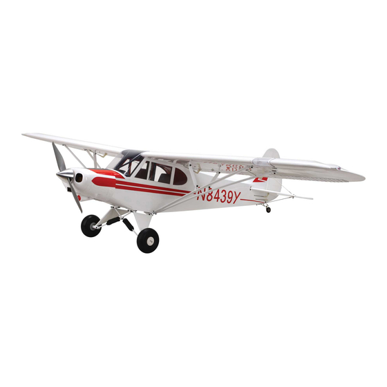
Hardware/Accessory Sizes ........4 Recommended Radio Equipment ........ 4 The Super Cub 25e ARF expertly captures the look Specifications Power 25 Motor Setup ..........4 and feel of this aviation classic with an accurate scale outline and features unlike anything ever seen in Power 32 Motor Setup .......... -
Page 4: Contents Of Kit/Parts Layout
3-inch (152mm) Servo EFLA618 Extension 18-inch (2ea) (2) White HANU870 Extension EFLA617 Y-Harness Heavy Duty 6-inch True Red HANU866 (Bind plug extension) DUB435 DuBro 1/16-inch Shrinkwrap SPMA3058 Standard Y-Harness (Receiver to flap fuselage extension) E-flite Super Cub 25e ARF Assembly Manual... -
Page 5: Required Tools And Adhesives
Balancing stand (optional) in relationship to the pilot sitting in the cockpit of the aircraft unless noted otherwise. Adhesives 30-minute epoxy PAAPT39 Medium CA PAAPT02 Thin CA PAAPT08 Threadlock PAAPT42 Formula 560 Canopy Glue PAAPT56 E-flite Super Cub 25e ARF Assembly Manual... - Page 6 Check to make sure the flap is positioned as described in steps 4 and 5. 5. Check that the flap can move freely through its range of motion. This will ensure that the hinges are installed correctly. E-flite Super Cub 25e ARF Assembly Manual...
- Page 7 CA to wick into. This will allow the CA to penetrate the hinge, creating a better bond between the hinge and surrounding wood. E-flite Super Cub 25e ARF Assembly Manual...
-
Page 8: Aileron And Flap Servo Installation
8. 1. Remove the aileron servo cover from the wing. You may need to use a covering iron to reseal the covering to the wing if the tape lifts the covering. E-flite Super Cub 25e ARF Assembly Manual... - Page 9 Use a #1 Phillips screwdriver to tighten the screw that secures the servo horn to the servo output. 8. Repeat steps 2 through 7 for the flap servo. E-flite Super Cub 25e ARF Assembly Manual...
- Page 10 8mm washer-head, self-tapping screws and a #1 the servo lead as shown. surrounding wood. Remove the screw before Phillips screwdriver. moving to the next step. E-flite Super Cub 25e ARF Assembly Manual...
- Page 11 Make sure the aileron is centered when the clevis is connected. Adjust the clevis as needed to center the aileron. Slide the tubing over the forks of the clevis to keep it from opening accidentally in flight. E-flite Super Cub 25e ARF Assembly Manual...
- Page 12 23. Connect the flap linkage to the servo and the flap control horn. With the flap servo centered, adjust the linkage to achieve the mid-flap position as shown. 26. Repeat steps 23 through 25 for the flap servo. E-flite Super Cub 25e ARF Assembly Manual...
-
Page 13: Motor And Speed Control Installation
4-40 x 3/4-inch socket head cap screws. Use a 3/32-inch hex wrench to tighten the screws. Make sure to use threadlock on these screws to prevent them from vibrating loose. E-flite Super Cub 25e ARF Assembly Manual... -
Page 14: Cowling, Propeller And Flight Battery Installation
Use low-tack tape to prevent the extension from floss to secure the lead so it does not accidentally falling forward in the fuselage until it is plugged disconnect inside the fuselage. into the mounted receiver. E-flite Super Cub 25e ARF Assembly Manual... -
Page 15: Landing Gear Installation
3/32-inch hex wrench to secure the cone in position. Make sure the propeller is centered in the openings so the spinner does not rub against the prop blades, which could potentially cause them to fail. E-flite Super Cub 25e ARF Assembly Manual... - Page 16 1/8-inch hex wrench to prevent the shocks from moving freely where they fully tighten the hardware securing the landing gear are attached to the landing gear mounts. mounts to the fuselage. E-flite Super Cub 25e ARF Assembly Manual...
- Page 17 8. Slide the axle through the inner hub in the wheel. wheel can rotate freely on the axle. The inner hub is the one without the holes for the screws to pass through. E-flite Super Cub 25e ARF Assembly Manual...
-
Page 18: Stabilizer And Tail Bracing Installation
Remove any excess epoxy before it cures using a paper towel and isopropyl alcohol. E-flite Super Cub 25e ARF Assembly Manual... - Page 19 2-56 x 6 -inch threaded rods are located on the top of the stabilizer. Always use threadlock on metal-to-metal fasteners to prevent them from vibrating loose. E-flite Super Cub 25e ARF Assembly Manual...
-
Page 20: Elevator Installation
3. Use a #1 Phillips screwdriver to thread a 2mm x 8mm self-tapping screw into each of the pre-drilled holes to cut threads in the surrounding wood. Remove the screw before moving to the next step. E-flite Super Cub 25e ARF Assembly Manual... - Page 21 Check that the self-tapping screws and a #1 Phillips screwdriver. elevator can move without rubbing the stabilizer at the counter balance. E-flite Super Cub 25e ARF Assembly Manual...
-
Page 22: Rudder Installation
CA to wick into. This will allow the CA to penetrate the hinge, creating a better bond between the hinge and surrounding wood. E-flite Super Cub 25e ARF Assembly Manual... - Page 23 This will harden self-tapping screws and a #1 Phillips screwdriver. the threads so the screws do not easily strip the surrounding wood. Always use threadlock on metal-to-metal fasteners to prevent them from vibrating loose. E-flite Super Cub 25e ARF Assembly Manual...
- Page 24 7. Place a T-pin in the center of each of the three hinges. This will center the hinges equally in the aileron and wing when they are installed. E-flite Super Cub 25e ARF Assembly Manual...
- Page 25 If not, apply CA to those hinges that Check that the rudder can move without rubbing the are not glued and recheck. fin at the counter balance. E-flite Super Cub 25e ARF Assembly Manual...
-
Page 26: Tail Wheel Installation
10mm washer-head self-tapping screws and a #1 F. Press the light into position in the rudder. It Phillips screwdriver. may be necessary to use a very small amount of silicone adhesive to keep the light in position. E-flite Super Cub 25e ARF Assembly Manual... -
Page 27: Rudder And Elevator Servo And Linkage Installation
This will harden the threads so the screws do not easily strip the surrounding wood. 6. Repeat steps 4 and 5 to install the remaining tail wheel spring. E-flite Super Cub 25e ARF Assembly Manual... - Page 28 Connect the clevis to the hole shown in the drawing. 5. Install the rudder and elevator servos using eight servo mounting screws and a #1 Phillips screwdriver. Rudder Attach clevis to the outer hole Drawing not to scale E-flite Super Cub 25e ARF Assembly Manual...
- Page 29 With the servo centered, attach the servo horn to the servo using the screw provided with the servo and a #1 Phillips screwdriver. Drawing not to scale E-flite Super Cub 25e ARF Assembly Manual...
-
Page 30: Receiver Installation Without Cockpit Kit
(76mm) into the bind port. Secure the main and remote receivers in the fuselage using hook and loop tape. 3. Cut a piece of hook and loop tape to attach the remote receiver to the fuselage side. E-flite Super Cub 25e ARF Assembly Manual... -
Page 31: Servo Hatch Cover Installation
8mm washer-head self-tapping screw into each of the holes to cut threads in the surrounding wood. Remove the screw before moving to the next step. If you are installing the optional cockpit kit (EFL460018), you can skip step 1. E-flite Super Cub 25e ARF Assembly Manual... - Page 32 Remove the screw before moving to the next step. Important: If installing the optional scale cockpit, skip the installation of the upper window until the cockpit kit has been isntalled. E-flite Super Cub 25e ARF Assembly Manual...
-
Page 33: Cockpit Kit Installation (Optional)
9. The seats are held in position with magnets so they can be removed when installing the wing bolts. Install the seats as shown. Please note that the prototype seats are shown; the production seats are darker in color. E-flite Super Cub 25e ARF Assembly Manual... -
Page 34: Wing And Wing Strut Installation
1. Slide the aluminum wing tube into the socket in installed. the wing panel. The tube socket has a cap on it, so do not force the tube in any farther than it will easily slide. E-flite Super Cub 25e ARF Assembly Manual... - Page 35 This alignment is described in step 7. 4. Secure the wing to the fuselage using a nylon wing bolt. E-flite Super Cub 25e ARF Assembly Manual...
-
Page 36: Lighting Kit Installation (Optional)
When removing the wing, only remove the hardware attaching the wing struts to the wing strut tab at the fuselage. 10. Repeat steps 2 and 9 to install the remaining wing strut and jury strut assemblies. E-flite Super Cub 25e ARF Assembly Manual... - Page 37 4. Repeat steps 1 through 3 to prepare the second landing light. Press the lights into position in the wing. It may be necessary to use a very small amount of silicone adhesive to keep the lights in position. E-flite Super Cub 25e ARF Assembly Manual...
-
Page 38: Accessory Installation
The fit should be tight, so tape will not be needed to hold the cover in position. 10. Repeat steps 1 through 3, and 7 through 9 to install the remaining navigation light. E-flite Super Cub 25e ARF Assembly Manual... -
Page 39: Center Of Gravity
Mark the location of the CG on the top of the wing position if it is removed from your model. with a felt-tipped pen. After the first flights, the CG position can be adjusted for your personal preference. E-flite Super Cub 25e ARF Assembly Manual... -
Page 40: Control Throws
We highly recommend re-binding the radio system once all the control throws are set. This will Down: 5/32-inch 4mm keep the servos from moving to their endpoints until the transmitter and receiver connect. E-flite Super Cub 25e ARF Assembly Manual... -
Page 41: Range Test Your Radio
It’s best in a landing configuration to not try and drag the airplane in with flaps; you need to aim it at the ground and fly it in. E-flite Super Cub 25e ARF Assembly Manual... -
Page 42: Daily Flight Checks
Product, (iv) attempted service by anyone other than secured. resulting liability. If you as the purchaser or user are a Horizon Hobby authorized service center, or (v) not prepared to accept the liability associated with the Products not purchased from an authorized Horizon 3. -
Page 43: Warranty Services
RMA number are clearly written on the outside of 61822 USA the shipping carton. productsupport@horizonhobby.com Notice: Do not ship Lipo batteries to horizon. If you 877-504-0233 have any issue with a Lipo battery, please contact the appropriate horizon product Support office. E-flite Super Cub 25e ARF Assembly Manual... -
Page 44: Compliance Information For The European Union
(h) Not operate model aircraft while under the repaired model aircraft. influence of alcohol or while using any drug which could adversely affect the pilot’s ability to safely control the model. E-flite Super Cub 25e ARF Assembly Manual... - Page 45 (b) Fly using the assistance of a camera or First-Person View (FPV) only in accordance with the procedures outlined in AMA Document #550. E-flite Super Cub 25e ARF Assembly Manual...
-
Page 46: Building And Flying Notes
Building and Flying Notes E-flite Super Cub 25e ARF Assembly Manual... - Page 47 Building and Flying Notes E-flite Super Cub 25e ARF Assembly Manual...
- Page 48 The Spektrum trademark is used with permission of Bachmann Industries, Inc. E-flite, DSM, DSM2, DSMX, Celectra and the horizon hobby logo are trademarks or registered trademarks of horizon hobby, Inc. All other trademarks, service marks and logos are the property of their respective owners.