
Related Manuals for Jonsered Front Rider FRM13A


Summary of Contents for Jonsered Front Rider FRM13A
- Page 1 Operator's Manual Please read these instructions carefully and make sure you understand them before using the machine.
- Page 2 Svenska –...
-
Page 3: Table Of Contents
CONTENTS Operator’s Manual for FR 13 and FRM 13 A Introduction ............2 Maintenance ............19 Driving and transport on public roads ....2 Maintenance schedule ........19 Towing .............. 2 Dismantling of the machine hoods ....20 Use ..............2 Checking and adjusting the steering wires .. -
Page 4: Introduction
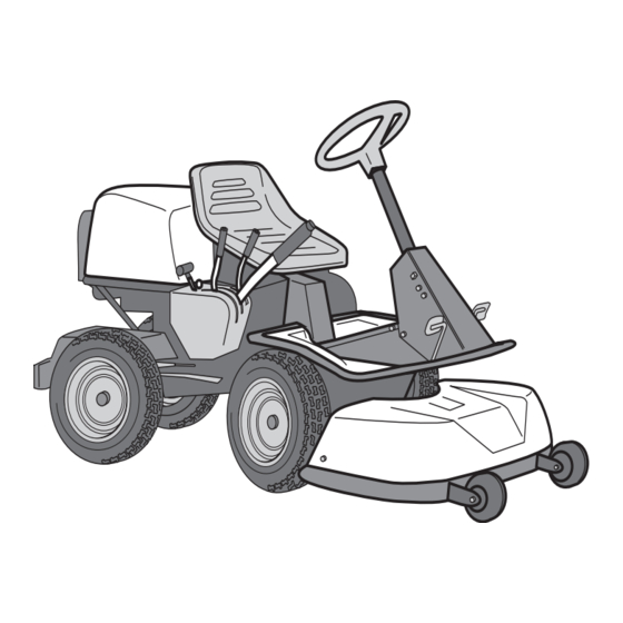
INSTRUCTION Dear customer Thank you for choosing a Front Rider. Front Riders are built to a unique design with a front-mounted cutting unit and a patented rear-wheel steering system. Riders are designed for maximum efficiency even in small or confined areas. The closely grouped controls and pedal-operated hydrostatic transmission (certain models) also contribute to the performance of this machine. -
Page 5: Serial Number
SAFETY INSTRUCTIONS Good service Jonsered products are sold all over the world and only through servicing dealers. This is to ensure that you, the customer, get the best support and service. Before the machine is delivered it undergoes inspection and is adjusted by your dealer. -
Page 6: Explanation Of Symbols
EXPLANATION OF SYMBOLS These symbols are on the machine and in the operator’s manual. Study them carefully so that you know what they mean. Read the operator’s manual Reverse Neutral Fast Slow Engine off Battery Choke Fuel Oil pressure Cutting height Backwards Forwards Ignition... -
Page 7: Safety Instructions
SAFETY INSTRUCTIONS These instructions are for your safety. Read them carefully. This symbol implies that important safety rules are applicable. This is for your safety and the operating reliability of the machine. General use: • Make yourself familiar with the controls and how to stop quickly. -
Page 8: Driving On Slopes
SAFETY INSTRUCTIONS • Watch out for traffic when working close to a road, or crossing one. • Be careful when rounding a fixed object so that the blades do not hit it. Never drive intentionally over a foreign object. • The machine is heavy and can cause very severe crush injuries. -
Page 9: Children
SAFETY INSTRUCTIONS • Do not cut close to edges, ditches or banks. The machine can suddenly tip over if a wheel goes over the edge of a drop or a ditch, or if a bank gives way. • Do not cut wet grass. It is slippery and the tyres can loose their grip so that the machine slides. - Page 10 SAFETY INSTRUCTIONS • Avoid overfilling. If fuel has been spilt on the Rider wipe it up and wait until it has evaporated before starting the engine. If fuel is spilt on clothes, change them. • Be extra careful when handling battery acid. Spilling acid on the skin can cause severe burn injuries.
-
Page 11: Presentation
PRESENTATION Presentation FR 13 has an in-line gearbox with five forward Congratulation on your choice of a first-class quality gears and one reverse gear. product. This manual describes two models that are fitted with engines from Briggs & Stratton of 12.5 On the FRM 13 A the power transmission from the horsepower. -
Page 12: Throttle/Choke Lever
PRESENTATION FR 13 Throttle and Choke lever The engine speed is adjusted with the throttle control, and thereby also the rotation speed of the blades. The control is also used to activate the choke function. When the choke is used the engine receives a richer mixture of fuel and air, which simplifies cold start. -
Page 13: Throttle Pedal
PRESENTATION FRM 13 A Throttle and Choke lever The engine speed is adjusted with the throttle control, and thereby also the rotation speed of the blades. The control is also used to activate the choke function. When the choke is used the engine receives a richer mixture of fuel and air, which simplifies cold start. -
Page 14: Cutting Unit
PRESENTATION Cutting unit FR 13 have a cutting unit with rear ejection, i.e. the grass cuttings are thrown out behind the cutting unit. FRM 13 A have a twin-blade BioClip cutting unit. Lift lever for cutting unit The lift lever is used to set the cutting unit in trans- port or cutting position. -
Page 15: Lever For Adjustment Of Cutting Height
PRESENTATION Lever for adjustment of cutting height With this lever the cutting height can be adjusted to 9 different positions. Cutting unit with rear ejection, 40-90 mm. BioClip cutting unit, 45-95 mm. Seat The seat has a jointed attachment on the front edge and can be tipped forward. -
Page 16: Driving
DRIVING Before starting • Read the safety instructions and information on the location and function of the controls before starting (see pages 5–13). • Conduct daily maintenance before starting (see maintenance schedule on page 19). Adjust the seat to the required position. Starting the engine 1. - Page 17 DRIVING Cold engine: 4. Push the throttle control to position 3 (choke position). In this position the engine receives a richer mixture so that the engine starts more easily. Warm engine: 5. Set the throttle control midway between position 1 and 2. 6.
-
Page 18: Driving The Machine
DRIVING 7. When the engine has started release the ignition key to neutral position. Push the throttle control to the required speed. For cutting 3/4 to full throttle. STOP START WARNING! Never run the engine indoors, in enclosed or poorly ventilated areas. The exhaust fumes contain toxic carbon monoxide. -
Page 19: Cutting Tips
DRIVING 3. Select the required cutting height (1-9) with the cutting height lever. To obtain a uniform cutting height it is important that the tyre pressures are equal on both front wheels (60 kPa). 4. Push in the lock button on the lift lever and lower down the cutting unit. -
Page 20: Stopping The Engine
DRIVING WARNING! Never drive the machine on ground with a slope of more than 15°. Mow slopes upwards and downwards, never across. Avoid sudden changes in direction. Hill start, manual gearbox 1. Press down the parking brake. 2. Push the throttle control to 3/4 position to full MAX 15°... -
Page 21: Maintenance
MAINTENANCE Maintenance schedule The following is a list of the maintenance which should be conducted on the machine. For the items which are not described in these instructions go to an authorised service workshop. Maintenance interval Daily in hours mainte- Maintenance Page nance... -
Page 22: Dismantling Of The Machine Hoods
MAINTENANCE Dismantling of the machine hoods Engine hood The engine is accessible for servicing when the engine hood is lifted up. Tilt the seat forward, release the rubber strap under the seat, and tilt the hood backwards. Front hood FR 13 Release the screws in the front hood (3) and lift off the hood. - Page 23 MAINTENANCE Right-hand fender Remove the screws (2 and 3) from the fender. On the FRM 13 A the knob (1) must also be removed. Left-hand fender Release the screws in the fender and lift off the fender. English –...
-
Page 24: Checking And Adjusting The Steering Wires
MAINTENANCE Checking and adjustment of the steering wires The steering is controlled by means of wires. These can in time become slack, which implies that the adjustment of the steering becomes altered. Check and adjust the steering as follows: 1. Dismantle the frame-plate by releasing the screws (two on each side). -
Page 25: Checking And Adjusting The Brakes
MAINTENANCE Checking the brake FR 13 The brake is of the disc brake type and is fitted on the gearbox. Check that the brake is correctly adjusted by measuring the distance between the brake lever and the front edge of the recess on the chassis. The distance should be 0–1 mm when the brake is not applied. -
Page 26: Checking And Adjustment Of Throttle Wire
MAINTENANCE Checking and adjustment of the throttle wire If the engine does not respond as it should when the throttle lever is moved, or if it produces black smoke or does not reach top speed, the throttle wire may need adjusting. 1. -
Page 27: Replacement Of Air Filter
MAINTENANCE Replacing the air filter If the engine seems to lack power or goes irregu- larly the reason may be that the air filter is clogged. It is therefore important to replace the air filter at regular intervals (see maintenance schedule on page 19 for correct service interval). -
Page 28: Checking The Fuel Pump's Air Filter
MAINTENANCE Checking of the fuel pump’s air filter Check regularly that the fuel pump’s air filter is free from dirt. The filter can when necessary be cleaned with a brush. Check the level of the battery acid Check that the level of the battery acid lies between the markings. -
Page 29: Checking The Safety System
MAINTENANCE Inspecting the safety system Check that the engine stops if you temporarily The Rider is equipped with a safety system that move out off the driver’s seat while the cutting unit prevents starting or driving under the following is lowered or the hydrostat pedals are not in the conditions: neutral position. -
Page 30: Checking The Tyre Pressure
MAINTENANCE Checking the tyre pressure The tyre pressure should be 60 kPa (0.6 kp/cm ) all round. To improve driving the pressure on the rear tyres can be reduced to 40 kPa (0.4 kp/cm The maximum tyre pressure is 100 kPa (1.0 kp/cm IMPORTANT INFORMATION Different tyre pressures on the front tyres will result in the blades cutting the grass... -
Page 31: Checking And Adjusting The Cutting Unit Ground Pressure
MAINTENANCE Checking and adjustment of the cutting unit’s ground pressure on FRM 13 A To achieve the best cutting results the cutting unit should follow the underlying surface without press- ing too hard against it. The pressure is adjusted with a screw on each side of the machine. -
Page 32: Adjusting The Parallelism Of The Cutting Unit
MAINTENANCE Adjustment of the cutting unit’s parallelism for the FR 13 1. Check the tyre air pressure. It should be 60 kPa (0,6 kp/cm 2. Dismantle the front hood and right-hand fender as described on page 20-21. 3. Vertical adjustment of the cutting unit is made with the adjusting nuts on the back edge of the lift-strut. -
Page 33: Service Position For Bioclip 90
MAINTENANCE FRM 13 A Service position for BioClip 90 The cutting head can be placed in the service position to provide easy access for cleaning, repairs and servicing. In the service position the cutting unit is raised and locked in the vertical position. Placing in service position 1. - Page 34 MAINTENANCE FRM 13 A 4. Fit the support wheels on either side of the rear of the cutting unit. WARNING! Wear protective glasses when dismantling the cutting unit. The spring which tensions up the belt can go off and cause personal injury.
- Page 35 MAINTENANCE FRM 13 A 8. Lift off the drive belt (1). Then pull out the pin (2). Take care not to get your hand trapped. 9. Pull the frame forwards and refit the pin. 10. Grasp the front edge of the cutting unit, pull out and raise into the service position.
-
Page 36: Checking The Blades
MAINTENANCE Checking the blades To achieve the best mowing results it is important that the blades are undamaged and well-sharpened. Check that the blades’ attachment screws are tight. IMPORTANT INFORMATION Replacing or sharpening the blades should be conducted by an authorised service workshop. -
Page 37: Changing The Oil
LUBRICATION Check the engine’s oil level Check the oil level in the engine when the machine is horizontal. Raise the engine cover as described on page 18. Release the dip stick and pull out. Wipe off the oil and insert again. The dip stick must be fully screwed down. -
Page 38: Checking The Transmission's Oil Level
LUBRICATION Check the transmission’s oil level FRM 13 A 1. Lift off the transmission cover. Release the two screws (one of each side) and lift off the trans- mission cover. 2. Check that there is oil in the transmission oil tank. -
Page 39: Lubrication Of Front Wheel Bearings
LUBRICATION Lubrication FR 13 Lubrication of front wheel bearings On Riders with rear ejection the hood and wings must be removed so that the bar can be raised to allow removal of the wheel. 1. Remove the plastic cover on the hub. 2. -
Page 40: Trouble Shooting Schedule
TROUBLE SHOOTING SCHEDULE Problem Procedure Engine will not start. • Fuel tank empty. • Plug defective. • Plug connection defective. • Dirt in carburettor or fuel pipe. Starter does not pull round engine. • Battery flat. • Bad contact between cable and battery terminal. •... -
Page 41: Storage
STORAGE Winter storage To put the machine in order for storage follow these instructions: At the end of the season the machine should 1. Carefully clean the machine, especially under immediately be put in order for storage, also if it is the cutting unit. -
Page 42: Technical Data
TECHNICAL DATA Dimensions FR 13 FRM 13 A Length 2000 mm 2145 mm Width 960 mm 1050 mm Height 1060 mm 1060 mm Unladen weight 225 kg 245 kg including cutting unit Wheel base 820 mm 855 mm Track 625 mm front 715 mm, rear 625 mm Tyre size 16 x 6.50 x 8... - Page 43 We, Husqvarna AB, S-561 82 Huskvarna, Sweden, tel. +46 36-146500, declare under sole responsibility that the rider mowers Jonsered FR 13 and FRM 13 A from 1998’s serial numbers and onwards (the year is clearly stated in plain text on the type plate with subsequent serial number), is in conformity with the following standards or other normative documents following the provisions in the COUNCIL’S DIRECTIVES:...
- Page 44 SERVICEJOURNAL FR 13/FRM 13 A Work done Date, mileage, stamp, sign Pre-delivery service 1. Top up battery with acid and recharge for four hours. 2. Fit steering wheel, seat and any optional equipment. 3. Adjust cutting unit: Adjust the lifting springs (the “weight” of the cutting unit should be 12-15 kg).
- Page 45 SERVICEJOURNAL Date, mileage, stamp, sign Work done ○ ○ ○ ○ ○ ○ ○ ○ ○ ○ ○ ○ ○ ○ ○ ○ ○ ○ ○ ○ ○ ○ ○ ○ ○ ○ ○ ○ ○ ○ ○ ○ ○ ○...
- Page 46 SERVICEJOURNAL Date, mileage, stamp, sign Work done ○ ○ ○ ○ ○ ○ ○ ○ ○ ○ ○ ○ ○ ○ ○ ○ ○ ○ ○ ○ ○ ○ ○ ○ ○ ○ ○ ○ ○ ○ ○ ○ ○ ○...
- Page 47 English –...
- Page 48 108 87 96-26 ´*xo^¶6e¨ 2000W50...