Table of Contents
Advertisement
Quick Links
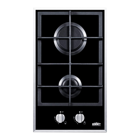
BUILT-IN CERAMIC GAS COOKTOPS
Dear Customer,
Thank you for buying one of our ceramic gas cooktops. We are sure
that this modern, functional and practical appliance, made using the
finest quality materials, will fully satisfy your requirements.
This new appliance is very easy to use, but in order to obtain the best
results, we strongly recommend that you read this booklet carefully
before use. The manufacturer cannot be considered responsible for
any damages to people or things in the event of incorrect installation or
improper use of this appliance.
We reserve the right to make any changes to our products which we
consider to be necessary or useful, also in the interest of the user,
without affecting the essential characteristics in terms of functionality
and safety.
Models GC2BGL
GC424BGL
Instruction Manual
The staff of
Felix Storch, Inc.
Summit Appliance Division
770 Garrison Avenue
Bronx, New York 10474
www.summitappliance.com
Advertisement
Table of Contents

Related Manuals for Summit GC2BGL


Summary of Contents for Summit GC2BGL
- Page 1 BUILT-IN CERAMIC GAS COOKTOPS Models GC2BGL GC424BGL Instruction Manual Dear Customer, Thank you for buying one of our ceramic gas cooktops. We are sure that this modern, functional and practical appliance, made using the finest quality materials, will fully satisfy your requirements.
-
Page 2: Table Of Contents
TABLE OF CONTENTS Important Safeguards ..............2 Location of Parts ................3 Installation ................. 4 - 7 Installing the Cooktop .............. 4 Sealing the Cooktop ..............5 Room Ventilation ..............5 Gas Connection ..............6 Electrical Connection ............6 - 7 Adjustments ................... -
Page 3: Important Safeguards
IMPORTANT SAFEGUARDS This product must be installed in conformity with local codes or, in absence of • local codes, with the National Fuel Gas Code, ASNI Z223.1/NFPA 54. The product must be electrically grounded in accordance with local codes or, •... -
Page 4: Location Of Parts
LOCATION OF PARTS Part No. Description Heat supplied Fast burner 8350 Btu/h Semi-fast burner, front 4350 Btu/h Semi-fast burner, back 4350 Btu/h Auxiliary burner 3400 Btu/h Grate Burner no. 2 control knob Burner no. 5 control knob Burner no. 4 control knob Burner no. -
Page 5: Installation
Always comply with the measurements given for the hole into which the appliance will be recessed (see Figs. 1 and 2). 30" Min. 6" Fig. 2 Fig. 1 Use These Dimensions (in inches) Model No. GC2BGL 11¼ 19⅛ 2¼ 2¼ 2⅞ GC424BGL 21¾ 18⅝... -
Page 6: Sealing The Cooktop
Sealing the Cooktop The cooktop has a special seal that prevents liquid from getting into the cabinet below. Follow these instructions exactly in order to apply this seal correctly: Detach the seals from their backing, checking that the transparent protection still adheres to the seal itself. -
Page 7: Gas Connection
Gas Connection Natural Gas and Propane Gas Natural gas installations require the connection of a gas regulator to the cooktop. You will find this regulator among the accessories supplied with the appliance. Assemble the regulator (noting the direction of gas flow) and transition pieces (supplied) in accordance with the figure below. -
Page 8: Electrical Connection
When the appliance is connected to electrical power by a socket: Fit a standard plug suited to the load indicated on the data label to the cable. • Fit the wires following Fig. 5, noting the following correspondences: • Letter L (live) = wire Letter N (neutral) = wire Ground symbol = green or yellow-green wire... -
Page 9: Adjustments
ADJUSTMENTS Always disconnect the appliance from the electrical power source before making any adjustments. All seals must be replaced by the technician when any adjustments are completed. Taps "Reduced rate" adjustment: 1. Switch on the burner and turn the corresponding knob to the "Reduced rate" position (small flame icon, Fig. -
Page 10: Conversions
CONVERSIONS Replacing Nozzles The burners can be adapted to suit different types of gas by fitting the nozzles that corres- pond to the gas used. To do this, it is necessary to remove the burner heads and use a straight key "B", to unscrew the nozzle "A"... -
Page 11: Using The Cooktop
USING THE COOKTOP Lighting the burners A diagram is screened beside each knob on the control panel of your cooktop. This diagram indicates to which burner the knob in question corresponds. After having opened the gas main or bottled gas tap, light the burners as described below: The knobs of the burners are equipped with a safety cut-off device. - Page 12 WARNINGS: Burners will only ignite when the corresponding knob has been set to the Full- • on position (large flame icon, Fig. 8). Matches can be used to ignite the burners during a power outage, but use • caution. Never leave the appliance unattended when the burners are being used. •...
-
Page 13: Cleaning
CLEANING CAUTION: Before cleaning the appliance, disconnect it from the gas and electricity supplies. If you wish to maintain the shine of the ceramic surface, treat the glass with a silicon-based film product before use to protect the surface against water and dirt. - Page 14 The enamaled grids, enameled covers "A", "B" and "C", and burner heads "M" (see Figs. 11 and 11a) must also be washed and the ignition elements "AC" and safety cut-off sensors "TC" (see Fig. 11b) must be cleaned. Do not wash them in the dishwasher.
-
Page 15: Servicing
SERVICING Always disconnect the appliance from the electric and gas mains before proceeding with any servicing operation. Replacing Components To replace the components housed inside the appliance, remove the trivets and the burners from the upper part of the cooktop. Remove the fixing screws "V" of the burner (Fig. -
Page 16: Limited Warranty
Call customer service toll free in the U.S.A. @ 1-800-932-4267, Monday to Friday 9:00 am. - 5:00 p.m. (ET). Order parts online at www.summitappliance.com/support Felix Storch, Inc. Phone: (718) 893-3900 Summit Appliance Division Fax: (718 )842-3093 770 Garrison Avenue Web Site: Bronx, NY 10474 www.summitappliance.com...