Table of Contents
Advertisement
Available languages
Available languages
Quick Links
BUILT-IN GAS COOKTOPS
GCJ1SSLP
GCJ2SSLP
GCJ4SSLP
GCJ5SSLP
GCJ536SSLP
GC433SSLP
GC431WLP
GC432BLP
GCJ1SS
GCJ2SS
GCJ4SS
GCJ5SS
GCJ536SS
GC433SS
GC431W
GC432B
BEFORE USE, PLEASE READ AND FOLLOW ALL SAFETY RULED AND
User Manual
Models:
LCG1SLP
LCG2SLP
LCG4SLP
LCG5SLP
LCG536SLP
ZSSG30LP
WGL30LP
TGL30BLP
LCG1S
LCG2S
LCG4S
LCG5S
LCG536S
ZSSG30
WGL30
TGL30B
OPERATING INSTRUCTIONS
SGC1SSLP
SGC2SSLP
SGC4SSLP
SGC5SSLP
SGC536SSLP
LCG30SSLP
LCG30WLP
LCG30BLP
SGC1SS
SGC2SS
SGC4SS
SGC5SS
SGC536SS
LCG30SS
LCG30W
LCG30B
Advertisement
Chapters
Table of Contents

Related Manuals for Summit GCJ1SSLP


Summary of Contents for Summit GCJ1SSLP
- Page 1 BUILT-IN GAS COOKTOPS User Manual Models: GCJ1SSLP LCG1SLP SGC1SSLP GCJ2SSLP LCG2SLP SGC2SSLP GCJ4SSLP LCG4SLP SGC4SSLP GCJ5SSLP LCG5SLP SGC5SSLP GCJ536SSLP LCG536SLP SGC536SSLP GC433SSLP ZSSG30LP LCG30SSLP GC431WLP WGL30LP LCG30WLP GC432BLP TGL30BLP LCG30BLP GCJ1SS LCG1S SGC1SS GCJ2SS LCG2S SGC2SS GCJ4SS LCG4S SGC4SS GCJ5SS...
- Page 2 Dear customer, Thank you for buying one of our products. We are sure that this new, modern, functional, and practical appliance, made using the finest quality materials, will fully satisfy your requirements. This new appliance is very easy to use, but in order to obtain the best results, we strongly recommend that you read this booklet carefully before use.
-
Page 3: Table Of Contents
TABLE OF CONTENTS Equipment Safety Location of Parts Installation Instructions 7-12 Installing the Cooktop The Burner Flames Overhead Cabinets Dimensions Chart Sealing the Cooktop Room Ventilation Gas Connection Natural and Propane Gas Electrical Connection Electrical Grounding Adjustments Conversions 14-15 Replacing Nozzles Adjust the Pressure Regulator Operating the Cooktop 16-17... -
Page 4: Equipment Safety
EQUIPMENT SAFETY Your safety and the safety of others are very important. We have provided many important safety messages in this manual and on your unit. Always read and obey all safety messages. If the information in this manual is not followed exactly, a fire or explosion may result causing property damage, personal injury or death. - Page 5 • Burners will only ignite when the corresponding knob has been set to the Full-on position (large flame icon, Fig. 8). • Matches can be used to ignite the burners during a power outage, but use caution. • Do not let the burner flame extend beyond the edge of the pan. Turn off all controls when not cooking.
-
Page 6: Location Of Parts
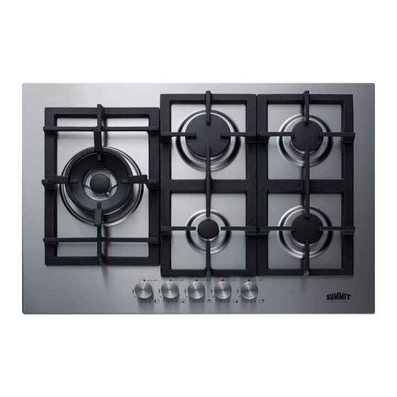
LOCATION OF PARTS Number Description Heat Supplied 11,900 – 12,700 Btu/h Ultra-rapid burner Rapid burner 10,000 Btu/h Semi-rapid burner 6,000 Btu/h Auxiliary burner 3,400 Btu/h Grate Burner No. 3 control knob Burner No. 4 control knob Burner No. 2 control knob Burner No. -
Page 7: Installation Instructions
INSTALLATION INSTRUCTIONS Installation, adjustment of controls and maintenance must only be carried out by qualified personnel. Incorrect installation may cause damage to persons, animals or property for which the manufacturer will not be considered responsible. During the life of the system, the automatic safety or regulating devices on the appliance may only be modified by the manufacturer or by his duly authorized dealer. -
Page 8: Dimensions Chart
Dimensions Chart Use These Dimensions (in inches) Model No. Cutout Width Cutout Depth Exterior Exterior Depth Height GCJ1SS/LP Width 11 1/4 ” 19” 12” 20” 3 1/4” 1 burner, 5 kW Use These Dimensions (mm) Exterior Exterior Depth Model No. Cutout Width Cutout Depth Height... -
Page 9: Sealing The Cooktop
Use These Dimensions (in inches) Model No. Cutout Width Cutout Depth Exterior Exterior Depth Height Width GC433SS/LP GC431W/LP GC432B/LP 21 3/4” 18 7/8” 29 1/2” 20 1/16” 1 7/8“ 4 burners, 75 cm Use These Dimensions (mm) Model No. Cutout Width Cutout Depth Exterior Exterior Depth Height... -
Page 10: Room Ventilation
Room Ventilation To ensure proper operation of the appliance, be sure that the room where it is installed has adequate ventilation. The appliance should not be installed with a ventilation system that blows air downward toward the appliance. It may cause ignition and combustion problems with the gas cooking appliance resulting in personal injury or unintended operation. -
Page 11: Natural And Propane Gas
Natural Gas and Propane Gas • Natural gas installations require the connection of a gas regulator to the cooktop. You will find this regulator among the accessories supplied with the appliance. • Assemble the regulator (noting the direction of gas flow) and transition pieces (supplied) in accordance with the figure below: •... -
Page 12: Electrical Grounding
Electrical Grounding This appliance is equipped with a (three-prong) (four-prong) grounding plug for your protection against shock hazard and should be plugged directly into a properly grounded receptacle. Do not cut or remove the grounding prong from this plug. -
Page 13: Adjustments
ADJUSTMENTS Always disconnect the appliance from the electrical power source before making any adjustments. All seals must be replaced by the technician when any adjustments are completed. Taps "Reduced rate" adjustment: 1. Switch on the burner and turn the relative knob to the “Reduced rate” position (small flame, fig. 8 page 12). -
Page 14: Conversions
CONVERSIONS CAUTION: Shut off the gas supply prior to disconnecting the electrical power, before proceeding with the conversion. Replacing Nozzles • The burners can be adapted to suit different types of gas by fitting the nozzles that correspond to the gas used. To do this, it is necessary to remove the burner heads and use a straight key "B"... - Page 15 INJECTOR NOMINAL MANIFOLD DIAMETER HEAT BURNERS INPUT PRESSURE (Btu/h) 1/100 mm inches water Max. column N° DESCRIPTION PROPANE HD 100 B 11 900 - 5 NATURAL ULTRA RAPID 175 B 12 700 PROPANE HD 95 B 10 000 - 5 NATURAL RAPID 155 B 10 000...
-
Page 16: Operating The Cooktop
OPERATING THE COOKTOP Lighting the Burners A diagram is screened beside each knob on the control panel of your cooktop. This diagram indicates to which burner the knob in question corresponds. After having opened the gas main or bottled gas tap, light the burners as described below: The knobs of the burners are equipped with a safety cut-off device. -
Page 17: The Dual Burner
The “Dual” Burner Separate regulation of the inner and outer rings (in practical terms, a dual burner controlled by a single knob), offers flexible use thanks to the possibility to light either the inner flame only or the whole burner (inner and outer flames at the same time). -
Page 18: Cleaning
CLEANING CAUTION: Always disconnect the appliance from the gas and electricity supplies before carrying out any cleaning operation. Continuous use can cause the burners to change color due to the high temperature. To properly clean your appliance, follow these steps: Periodically wash the hot plate, the enameled steel pan support, the enameled burner caps “A”, “B”... -
Page 19: Servicing
SERVICING Always disconnect the appliance from the electric and gas supplies before proceeding with any servicing operation. Replacing Components • To replace the components housed inside the appliance, remove the trivets and the burners from the upper part of the cooktop. Remove the fixing screws "V" of the burner (Fig. 13) and the knobs using hand pressure to remove them from the appliance. -
Page 20: Limited Warranty
LIMITED WARRANTY ONE YEAR LIMITED WARRANTY Within the 48 contiguous United States, for one year from the date of purchase, when this appliance is operated and maintained according to instructions attached to or furnished with the product, warrantor will pay for factory- specified parts and repair labor to correct defects in materials or workmanship. - Page 21 LA TABLE DE CUISSON AU GAZ ENCASTRABLE Manuel de l'Utilisateur Des modèles: GCJ1SSLP LCG1SLP SGC1SSLP GCJ2SSLP LCG2SLP SGC2SSLP GCJ4SSLP LCG4SLP SGC4SSLP GCJ5SSLP LCG5SLP SGC5SSLP GCJ536SSLP LCG536SLP SGC536SSLP GC433SSLP ZSSG30LP LCG30SSLP GC431WLP WGL30LP LCG30WLP GC432BLP TGL30BLP LCG30WLP GCJ1SS LCG1S SGC1SS GCJ2SS...
- Page 22 Cher client, nous vous remercions d’avoir choisi nos produits. Nous vous assurons que ce nouvel appareil moderne, fonctionnel et pratique à la fois, fabriqué avec des matériaux de première qualité, sera satisfaire pleinement vos exigences. Ce nouvel appareil est très facile d’utilisation, mais afin d’obtenir les meilleurs résultats, nous vous recommandons tout particulièrement, de lire attentivement cette notice avant toute utilisation.
- Page 23 TABLE DES MATIÈRES Sécurité des Equipmentes 24-25 Position des Composants Instructions d’Installation 27-32 Installation de la Table de Cuisson Les Flammes Debruleur Unités Murales Fixation de la Table de Cuisson Ventilation de la Piece Raccordement au Gaz Gaz Naturel et Gaz Propane Branchement Electique 31-32 Mise à...
-
Page 24: Sécurité Des Equipmentes
SECURITE DES EQUIPEMENTS Votre sécurité et celle des autres sont très importantes. Le non-respect des instructions du présent manuel peut être à l’origine d’un incendie ou explosion causant des dommages matériels, corporels ou le décès. • Le produit doit être installé conformément à la déclaration que l'installation doit être conforme aux codes locaux ou, en l'absence de codes locaux, avec le National Fuel Gas Code, ANSI Z223.1 / NFPA 54. - Page 25 • L’utilisation d’un appareil de cuisson au gaz génère de la chaleur et humidité dans la pièce où celui- ci est installé. C’est pourquoi la pièce doit être correctement aérée. • Une utilisation intensive et sur une longue durée de l’appareil peut exiger une ventilation complémentaire.
-
Page 26: Position Des Composants
POSITION DES COMPOSANTS No. de la pièce Description Chaleur fournie 11,900 – 12,700 Btu/h Brûleur ultra rapide Brûleur rapide 10,000 Btu/h Brûleur semirapide 6,000 Btu/h Brûleur auxiliary 3,400 Btu/h Grille Manette de commande du brûleur n° 3 Manette de commande du brûleur n° 4 Manette de commande du brûleur n°... -
Page 27: Instructions D'installation
INSTRUCTIONS D'INSTALLATION L’installation, le réglage des commandes ainsi que l’entretien doivent être effectués uniquement par du personnel qualifié. Une installation incorrecte peut entraîner des dommages corporels ou matériels pour lesquels le fabricant ne sera pas tenu responsable. Pendant toute la durée de vie du système, les dispositifs de sécurité... - Page 28 Tableau des dimensions Dimensions à respecter (en pouces) Modèle Cutout Width Cutout Depth Exterior Exterior Height GCJ1SS/LP Width Depth 11 1/4” 19” 12” 20” 3 1/4” 1 Brûleur, 5 kW Dimensions à respecter (en mm) Modèle Cutout Width Cutout Depth Exterior Exterior Height...
-
Page 29: Fixation De La Table De Cuisson
Dimensions à respecter (en pouces) Modèle Cutout Width Cutout Depth Exterior Exterior Height GC536SS/LP Width Depth 32 3/4” 18 3/4” 33 7/8” 20” 3 1/4” 5 brûleurs, 90 cm Dimensions à respecter (en mm) Modèle Cutout Width Cutout Depth Exterior Exterior Height GC536SS/LP... -
Page 30: Ventilation De La Piece
Afin d’éviter tout contact éventuel avec la partie inférieure chaude de la table de cuisson, un revêtement horizontal en bois doit être installé et fixé à l’aide de vis, à une distance minimale de 2,5” en-dessous de la surface inférieure de la table de cuisson (voir Fig. 1). Ventilation de la pièce Pour assurer le bon fonctionnement de l’appareil, assurez-vous que la pièce où... -
Page 31: Gaz Naturel Et Gaz Propane
Méthode de Test de Pression • Enlevez la grille et le chapeau du brûleur • Enlevez le diffuseur aluminium de gaz • Enlevez les injecteurs temporaires • Connectez l’instrument de test sur la zone de filetage du porte-injecteur (M6x0,75) • Vérifiez si la table de cuisson a une pression correcte •... -
Page 32: Branchement Electique
Branchement électrique Les branchements électriques de l’appareil doivent répondre aux exigences des réglementations et dispositions locales. Avant de brancher l’appareil, vérifiez que : 1. La puissance électrique de la principale source d’électricité et des prises de courant soit adaptée à la puissance nominale maximale de l’appareil. -
Page 33: Réglages
RÉGLAGES Débranchez l’appareil du réseau d’alimentation électrique avant d’intervenir pour des réglages. Tous les joints doivent être changés par le technicien une fois les réglages terminés. Robinets Réglage du “débit réduit” : 1. Allumez le brûleur et tournez la manette correspondante sur la position “débit réduit” (petite flamme, fig. -
Page 34: Conversions
CONVERSIONS Avertissement: L'alimentation en gaz doit être coupée avant de débrancher l'alimentation électrique, avant de procéder à la conversion. Remplacement des buses • Il est possible d’adapter les brûleurs aux différents types de gaz en installant des buses qui correspondent au gaz utilisé. Pour ce faire, retirez les têtes des brûleurs et utilisez une clé droite •... - Page 35 DIAMÈTR E APPORT BRÛLEURS ORDINAIR E NOMINA L GA Z L’INJECTEU R COLLECT E UR PRESSION CHALEU R (Btu/h) 1/100 mm pouce s colonn e d’eau Max. N° DESCRIPTIO N PROPANE HD - 100 B 11 900 5 GAZ ULTRA 175 B 12 700 NATURE...
-
Page 36: Utilisation De La Table De Cuisson
UTILISATION DE LA TABLE DE CUISSON Allumage des brûleurs Un symbole est présent à côté de chaque manette sur le panneau de commande de votre table de cuisson. Ce symbole indique à quel brûleur correspond la manette de commande en question. Après avoir ouvert l’arrivée de gaz ou le robinet de la bouteille à... -
Page 37: Bruleurs Dual
Brûleurs « DUAL » Réglage de la couronne interne indépendamment de la couronne externe (c’est-à-dire un double brûleur commandé par un seul bouton), grande flexibilité d’utilisation grâce à la possibilité d’actionner uniquement la flamme interne ou tout le brûleur (simultanément les flammes interne et externe). Allumage et Fonctionnement du Brûleur Disposez la casserole sur le brûleur avant l’allumage. -
Page 38: Nettoyage
NETTOYAGE IMPORTANT: Débranchez toujours l’appareil du réseau d’alimentation électrique ou en gaz avant toute opération de nettoyage. Une utilisation continue entraîne une décoloration des brûleurs due à la température élevée. • Nettoyez périodiquement la plaque chauffante, la grille émaillée, les chapeaux émaillés « A », « B » et «... -
Page 39: Entretien
ENTRETIEN Débranchez toujours l’appareil du réseau d’alimentation électrique ou en gaz avant toute opération d’entretien. Remplacement des composants • Pour remplacer les composants installés à l’intérieur de l’appareil, enlevez les grilles et les brûleurs de la table de cuisson. Enlevez les vis de fixation « V » du brûleur (fig. 13) et les manettes en appuyant avec les mains, afin de retirer de l’appareil. -
Page 40: Garantie Limitée
GARANTIE LIMITEE Dans les Etats-Unis contigus, pendant un an a compter de la date d'achat, si l'appareil est utilise et entretenu conformement aux presentes instructions ou celles fournies avec le produit. Le garant s'engage a payer les pieces de rechange specifiees par l'usine et la main-d'reuvre de reparation pour corriger un vice de materiau ou de fabrication.