Newco Bistro 10 Operating Instructions Manual
Hide thumbs
Also See for Bistro 10:
- Operating instructions manual (28 pages) ,
- Operating instructions manual (28 pages) ,
- Restarting (5 pages)

Related Manuals for Newco Bistro 10


Summary of Contents for Newco Bistro 10
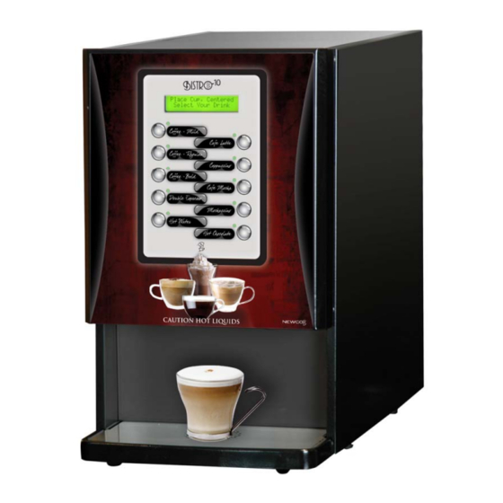
- Page 1 Bistro 10 Operating Instruction Manual Model B-10 1-800-325-7867 3650 NEW TOWN BLVD ST. CHARLES MO 63301 WWW.NEWCOCOFFEE.COM...
-
Page 2: Table Of Contents
Table of Contents Introduction & NEWCO Product Warranty……………….. Machine Dimensions & Specifications………………………. Machine Features……………………………………………... Plumbing Connections………………………………………... Installation Instructions……………………………………… Set Up for Bistro 10 Unit……………………………………... Product Installation Procedure………………………………. Drink Selection and Keypad Display………………………... Programming Instructions…………………………………… Programming-Machine Calibration…………………………. Programming-Changing Drink Recipes…………………….. Daily Cleaning…………………………………………………... -
Page 3: Warning Labels
Warning Labels NOTICE: Read and follow all notices posted on this machine. Do not damage or destroy these notices as they are for your protection WARNING DO NOT OVERLOAD CIRCUIT. ALWAYS ELECTRICALLY GROUND THE CHASSIS OR ADAPTOR PLUG. DO NOT DEFORM PLUG OR CORD. FOLLOW NATIONAL AND LOCAL ELECTRICAL CODES. -
Page 4: Introduction & Newco Product Warranty
SPECIFIED HEREIN, TO REPAIR, REPLACEMENT OR REFUND. In no event shall Newco be liable for any other damage or loss, including, but not limited to, lost profits, lost sales, loss of use of equipment, claims of Buyer’s customers, cost of capital, cost of down time, cost of substitute equipment, facilities or services, or any other special, incidental or consequential damages. -
Page 5: Machine Dimensions & Specifications
Machine Dimensions & Specifications 120 VAC-1600W HEATER-15A USA POWER SUPPLY 120 VAC-1400W HEATER-15A CANADIAN POWER SUPPLY 1/2 GALLON TANK 6-16 OZ CUP SIZE TEMPERATURE RANGE 180-205F PRODUCT SELECTION SWITCH CHOCOLATE & LATTE & INGREDIENT DISPLAY CABINET WATER INLET & POWER SWITCH DRIP TRAY &... -
Page 6: Machine Features
Machine Features • CALIBRATION NEEDED: POWDER PRODUCTS • WHIPPER RINSE BUTTON • AUTOMATIC POWDER LEVEL RESET • PRE-PROGRAMMED DRINK RECIPES • BUTTON ASSIGNMENT FOR RECIPES • INDEPENDENT POWDER HOPPER COUNTDOWN & RESET • CUSTOM CALL FOR SERVICE NUMBER • POWER SAVE & POWER DOWN OPTION •... -
Page 7: Plumbing Connections
Plumber’s Installation Instructions CAUTION: Disconnect Power to machine before proceeding with plumbing installation. Attach water line to water filter, rear of machine. Flush water line before installing machine. Machine should be connected to COLD WATER LINE ONLY. Water pressure should be at least 40 lbs. For less than a 25 ft run, use 1/4" copper tubing and connect to 1/2"... -
Page 8: Installation Instructions
Installation Instructions WARNING: - Read and follow installation instructions before plugging or wiring in machine to electrical circuit. Warranty will be void if machine is connected to any voltage other than that specified on the nameplate serial tag. Machine must be on a flat and level surface. Plug or wire in machine to appropriate voltage as noted on the brewer serial tag. -
Page 9: Set Up For Bistro 10 Unit
OR TIMES OUT AT 12 SECONDS Product Installation Procedure Fig. 1 Fig. 2 Fig. 3 • Open product box and remove the BIB product. Place in Coffee BIB Tray, Fig. 2, and (Newco PN 121929) as shown in Fig. 3. 2.10.14... - Page 10 Product Installation Procedure Cont’d Fig. 4 • Remove the plastic insert from the BIB fitment as shown in Figure 4. Fig. 5 • Using finger and thumb only to prevent over-tightening, thread the BIB connector on to the BIB fitment until seated as shown in Figure 5.
- Page 11 Product Installation Procedure Cont’d Fig. 6 • Place the product in the storage compartment as shown in Figure Fig. 7 • Position the tubing as shown in Figure 7 2.10.14...
-
Page 12: Drink Selection And Keypad Display
PROGRAM’S ACCESS AND RESET BUTTON Programming Instructions To enter into “Programming Mode”, hold the ‘Newco Logo’ button for 7 seconds.(Note: Sanitation mode will display after 2 seconds, continue holding button until ”Maintenance” is displayed.) Select Menu Maintenance The machine readout will display in the Message Display Area. - Page 13 1. Press Button to Select “Maintenance” 2. Press “LATTE” Button to toggle Select Menu display Install Sanitizing solution-Push Newco Coffee Logo to Start Sanitation Cycle (See Pages 22 - 26) Push & Hold Newco Coffee Logo to Prime Pump (See Pages 22 - 26)
- Page 14 Programming-Cont’d Setup 1. Press Button to Select “Setup” 2. Press Button to Toggle display Water Temperature Setting (170-205 F) Buzzer volume 0-25 Filter Monitoring (On or Off) Filter size 500 1000 1500 5000 gallons (Only displays if “ON”) Energy Save (Off, Semi [140F], Full [0FF] Energy Time -.5 to 4.0 Hrs.
- Page 15 Programming-Cont’d Assigning Recipes To buttons 1. Press Button to Select “Setup” 2. Toggle Selection to “Assign Recipes” 3. Select Assign Recipes 5. Select Recipe to be assigned a Button 4. Scroll Up & Down Recipe Choices with these Two 6. All lights will flash Buttons Depressing a button will assign the new...
- Page 16 Programming-Cont’d Changing “Call For Service” Number Note: Whenever the machine detects a service problem, a description of the problem and a “Call for Service” Telephone Number Scrolls across the Display. This number can be changed during machine Set-Up. Select the “Call for Service # in the “Set-Up” Menu 1.
-
Page 17: Programming-Machine Calibration
Programming -Machine Calibration Factory Defaults Value Mix Bowl Cal 26.0 oz. Calibration Left Auger Speed 1. Press Button to Select “Calibration” Left Auger Cal 156 grams 2. Toggle Selection to “Calibration” Right Auger Speed Right Auger Cal 90 grams 4. Press Button to Toggle display Coffee Cal 23.0 oz. - Page 18 Programming -Machine Calibration-Cont’d “Right Auger Speed” (Milk), this is the right or milk product auger delivery duty cycle value, 1-10, to adjust the auger motor speed for delivering powdered product. This Right value should remain at 9 or 10 for the Wolfgang Puck powdered products. Value is set Auger at 9 at the factory.
-
Page 19: Programming-Changing Drink Recipes
Programming-Changing the Drink recipes NOTE: Editing and Changing the Name of Changing the Drink recipes a “No Recipe” recipe will Create a “New” Drink for that Recipe #. 1. Press to Select Recipe Entry 3. Select Recipe to be Viewed or Edited 4. -
Page 20: Daily Cleaning
Daily Cleaning 1. Place empty cup in dispense area 2. Push and hold “Rinse” Button until water runs clear (Rinses Mixing bowl and Coffee Mix Chamber) Empty and remove cup 3. Rotate Tab on Whipper Base Counterclockwise to “Five O- Clock”... -
Page 21: Whipper Disassembly
Whipper Disassembly 767376 WHIPPER STEAM CAP 767195 WHIPPER MOTOR 767196 BASE, WHIPPER MOUNTING [O-Ring & Shaft Seal Included] 767197 WHIPPER IMPELLER 767365 WHIPPER BOWL 767200 WHIPPER NOZZLE 781566 WHIPPER SEAL (REPLACE AFTER 5000 CYCLES) 767390 O-RING WHIPPER BASE RED [NOT SHOWN] 2.10.14... -
Page 22: Cleaning And Sanitizing Instructions
Cleaning Instructions Fig. 1 Fig. 2 1. Remove product from storage area and disconnect BIB connectors as shown in figures 1 & 2. 2.10.14... - Page 23 Cleaning Instructions-Cont’d Fig. 3 2. Place an empty container in the dispense area of the machine as shown in figure 3. 2.10.14...
- Page 24 Cleaning Instructions-Cont’d 3. Connect the flushing solution Fig. 4 to the BIB connector from the pump as shown in figure 4. Flush Product & Type of Fittings: 900044: Easy Clean Flush Solution removed from the box. 400137: QCD Fitting 900044: Easy Clean Flush Solution 107117: Scholle Fitting 2.10.14...
- Page 25 Pump BIB connector and replace the coffee BIB product. The machine will automatically advance to the Prime Pumps mode. 7. To Prime: Press and hold the “Reset” [Newco] button until a steady stream of product flows from the dispense area into the vessel.
- Page 26 Weekly Cleaning Instructions 1. Following daily cleaning instructions above page 25 2. Remove the bag connector from the product box and disassemble or prop open the internal valve to allow free flow of product through the connector. NOTE: Cutting the mating fittings from an empty bag makes an excellent “free flowing”...
- Page 27 Weekly Cleaning Instructions – Cont’d For Your Information: If the “Easy-Clean” product is not being used or need to sanitize. These adaptors open the appropriate connector and then the hose ends can be dropped into your solution of cleaner or sanitizer. PN: 320282, QCD cleaning/flush adapter.
- Page 28 Whipper System Maintenance-Cont’d Lubrication As the whipper motor spins at a very high rate of speed, it is important to minimize friction between the motor shaft and the rubber seal to extend the life of both components. After disassembling and cleaning the whipper components with warmer water, add lubricant [item #: 900039] to the whipper motor shaft before re-installing the base.
- Page 29 Whipper System Maintenance-Cont’d Replacing Worn Components – Cont’d When replacing the seal [781566] on the whipper base, pay careful attention to the alignment marks on both the seal and the base. If the two are not properly aligned, the hole in the seal [for the motor shaft] will be oval shaped and not round.
- Page 30 Whipper System Maintenance-Cont’d Replacing Worn Components-Cont’d Pay extra attention when installing the impeller onto the whipper motor shaft. The impeller has an indicator arrow that must be aligned with the flat spot on the shaft for proper installation. If the impeller is forced onto the shaft without properly aligning it, it will become extremely difficult to remove the next time maintenance is required.
-
Page 31: Service Notes
Service Notes This machine uses advanced diagnostics to alert the operator should any of the motors or motor controllers sense the motors are not turning at the correct rate or sense a bad connection. These errors highlighted by a scrolling display such as “Call for Service— (Left Auger) Motor Error”, and the Service Number entered during machine set-up will be displayed. -
Page 32: Wiring Diagram
Wiring Diagram 2.10.14...