Bosch FAS-420-TM Operation Manual
Aspirating smoke detector
Hide thumbs
Also See for FAS-420-TM:
- Installation manual (99 pages) ,
- Quick installation manual (84 pages) ,
- Operation manual (100 pages)
Table of Contents
Advertisement
Quick Links
Advertisement
Table of Contents

Related Manuals for Bosch FAS-420-TM


Summary of Contents for Bosch FAS-420-TM
- Page 1 FAS-420-TM Aspirating Smoke Detector FAS-420-TM Operation Guide...
-
Page 3: Table Of Contents
General Introduction Safety Instructions Warranty Copyright Disposal Technical Specifications Product Description Areas of Application System Overview Functions FAS-420-TM Series Aspirating Smoke Detectors and Accessories 2.5.1 Overview 2.5.2 FAS-420-TM Series Connections 2.5.3 FAS-420-TM Displays 2.5.4 FAS-420-TM-R Displays 2.5.5 FAS-420-TM-RVB Displays 2.5.6 FAS-ASD-DIAG Diagnostic Software 2.5.7... - Page 4 | Table of Contents FAS-420-TM Aspirating Smoke Detector 3.7.3 M-pipe system 3.7.4 Double U-pipe system Simplified pipe planning 3.8.1 I-Pipe System - Simplified Planning 3.8.2 U-Pipe System - Simplified Planning 3.8.3 U-pipe System - Simplified Planning 3.8.4 Double U-Pipe System - Simplified Planning Planning for forced airflow 3.10...
- Page 5 Without any other pipe accessories 8.2.2 With water separator Planning with Air Filter 8.3.1 Without Any Other Pipe Accessories 8.3.2 With water separator Test Log for Aspirating Smoke Detectors in the FAS-420-TM Series Index Bosch Sicherheitssysteme GmbH Operation Guide F.01U.088.878 | 4.1 | 2010.11...
-
Page 6: General
This operation guide describes the smoke aspiration systems featuring FAS-420-TM series Aspirating Smoke Detectors and the associated aspiration pipe system. The FAS-420-TM designation in this operation guide refers to all FAS-420-TM series (FAS-420-TM, FAS-420-TM-R, FAS-420-TM-RVB) versions. Specific references are made to differences between the individual versions. -
Page 7: Disposal
FAS-420-TM Aspirating Smoke Detector General | en This operation guide is intended exclusively for installation engineers and their employees. Reprinting this operation guide or extracts thereof is permitted for internal purposes only. Disposal Unusable electrical and electronic devices or modules must not be disposed of with normal household refuse. -
Page 8: Technical Specifications
They are used for space and equipment protection as well as for monitoring air conditioning units or ducts (provided that the FAS-420-TM is installed outside of these units or ducts). You can also pinpoint the exact location of the fire using the innovative fire source identification operation. - Page 9 Extensive pipe accessories The extensive range of accessories enables the FAS-420-TM aspirating smoke detectors to be used even in the most difficult conditions. Products from air filters and condensate separators to blowing-out systems increase the service life in extremely dusty, damp and cold environmental conditions.
-
Page 10: Areas Of Application
| Technical Specifications FAS-420-TM Aspirating Smoke Detector Areas of Application Thanks to their detection principle, FAS-420-TM aspirating smoke detectors represent an extremely versatile fire protection solution. Principle Air samples are taken from the monitoring range by a pipe system with defined aspiration borings and then fed to the detector module. - Page 11 Figure 2.2 Monitoring options for an air-conditioning unit or an air- conditioning duct (depiction of principle) The FAS-420-TM Aspirating Smoke Detector can be used for early fire detection in areas with special-purpose air conditioning. Thanks to its high sensitivity, expensive goods and equipment can be monitored reliably. The...
-
Page 12: System Overview
| Technical Specifications FAS-420-TM Aspirating Smoke Detector 1 Clicking FAS / FCS Figure 2.3 Principle of equipment monitoring with FAS-420-TM series Aspirating Smoke Detectors System Overview The Smoke Aspiration Systems comprise a detector module, housing base and pipe system. -
Page 13: Functions
Detection Depending on the response sensitivity of the detector module in use and the alarm threshold programmed, the FAS-420-TM aspirating smoke detector triggers the alarm when the corresponding air obscuration threshold is reached. The alarm is displayed via the pre-alarm or main alarm LED on the device and forwarded to a connected fire panel. - Page 14 | Technical Specifications FAS-420-TM Aspirating Smoke Detector – Phase 2 As soon as the system has switched to alarm state as a result of a rise in the concentration of smoke particles typical of a fire, the alarm is signaled.
- Page 15 Figure 2.8 Phase 4: Identification of fire source by reversing the fan's direction of flow Once the fire source has been identified, it is displayed via a corresponding display on the FAS-420-TM-R/-RVB and on the operating and display unit of the fire panel. Detection Depending on the response sensitivity set on the detector module (0.5%/m to 2%/m light...
- Page 16 Pipe system A pipe system with an overall length of up to 50 m can be connected to FAS-420-TM series Aspirating Smoke Detectors over a maximum of 8 aspiration points. A maximum of 5 aspiration points can be connected with ROOM·IDENT.
-
Page 17: Fas-420-Tm Series Aspirating Smoke Detectors And Accessories
Infrared diagnostics port – FAS-420-TM: optical displays for main alarm, malfunction and operation – FAS-420-TM-R: optical displays for fire source identification, main alarm, malfunction and operation – FAS-420-TM-RVB: optical displays for fire source identification, pre-alarm and main alarm, malfunction and operation, smoke level display Information on other accessories for special applications can be found in –... -
Page 18: Fas-420-Tm Series Connections
| Technical Specifications FAS-420-TM Aspirating Smoke Detector 2.5.2 FAS-420-TM Series Connections Figure 2.11 FAS-420-TM Connections (see table below for explanations) FAS-420-TM Position Function Explanation Series Figure 2.1 For ∅ 25 mm pipe Connection for aspiration pipe system For ∅ 25 mm pipe... -
Page 19: Fas-420-Tm Displays
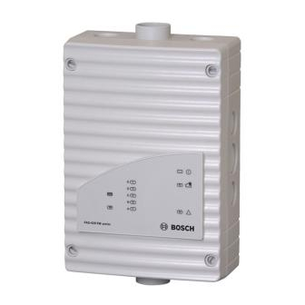
FAS-420-TM Aspirating Smoke Detector Technical Specifications | en 2.5.3 FAS-420-TM Displays Figure 2.12 FAS-420-TM displays FAS-420-TM Display Explanation Operation Green Operation display Main alarm Main alarm display Malfunction Yellow Malfunction – in the pipe system – in the detector module –... -
Page 20: Fas-420-Tm-R Displays
| Technical Specifications FAS-420-TM Aspirating Smoke Detector 2.5.4 FAS-420-TM-R Displays Figure 2.13 FAS-420-TM-R displays FAS-420-TM-R Display Explanation Operation Green Operation display Main alarm Main alarm display Malfunction Yellow Malfunction – in the pipe system – in the detector module –... -
Page 21: Fas-420-Tm-Rvb Displays
Figure 2.15 Diagnostic software for importing and reading out the device data The FAS-ASD-DIAG Diagnostic Software enables the saved and current statuses of the FAS-420-TM and error messages to be saved on a PC or laptop. Bosch Sicherheitssysteme GmbH Operation Guide... -
Page 22: Remote Indicators
256 colors. Diagnostic messages remain saved in the FAS-420-TM for at least 3 days in order to be able to evaluate even short, sporadically occurring errors (e.g. in case of changed operating conditions). -
Page 23: Air Sampling Openings
FAS-420-TM Aspirating Smoke Detector Technical Specifications | en During planning/design, a distinction is drawn between area monitoring and equipment monitoring. For both applications, PVC pipes and halogen-free pipes can be used. The pipes used for equipment monitoring should be halogen-free. - Page 24 | Technical Specifications FAS-420-TM Aspirating Smoke Detector Smoke aspiration pipe Air sampling opening with aspiration reducing film sheet Marking tape for aspiration reducing film sheet Air sampling opening Fire red (RAL 3000) Transparent Figure 2.18 Air sampling opening with aspiration reducing film sheet...
-
Page 25: Ceiling Lead-Through
FAS-420-TM Aspirating Smoke Detector Technical Specifications | en 2.6.3 Ceiling Lead-through Ceiling T-fitting Pipe system Complete ceiling lead- through Aspiration hose for ceiling lead-through False ceiling Knurled nut Aspiration reducing film sheet Aspiration Figure 2.20 Ceiling lead-throughs A concealed pipe system for area monitoring can be realized by installing in a false ceiling. -
Page 26: Water Separator For Humid Areas
Smoke aspiration pipe Air-return pipe Figure 2.22 FAS-420-TM with air-return pipe The air-return pipe is installed in the conical pipe connection for the air return of the FAS-420- TM (see Figure 2.22). It fits perfectly in the connection and guarantees a firm hold. When using fire source identification, it is not permitted to connect an air-return pipe. - Page 27 FAS-420-TM Aspirating Smoke Detector Technical Specifications | en Water separator Pipe system connection 45° pipe elbow Figure 2.23 FAS-ASD-WS Water Separator for condensing water vapor and collecting condensate from the pipe system The FAS-ASD-WS Water Separator can be operated in a temperature range from 0 °C to +50 °C.
-
Page 28: Scope Of Delivery: Smoke Aspiration System
| Technical Specifications FAS-420-TM Aspirating Smoke Detector Scope of Delivery: Smoke Aspiration System Basic Devices and Accessories Designation Order number FAS-420-TM Standard unit F.01U.078.495 FAS-420-TM-R Standard unit F.01U.078.496 FAS-420-TM-RVB Standard unit F.01U.078.497 FAS-420-TM-HB Housing Base F.01U.078.494 FAS-ASD-DIAG Diagnostic Software including connection cable, for F.01U.033.505... - Page 29 FAS-420-TM Aspirating Smoke Detector Technical Specifications | en Air sampling opening components Designation Order number Marking tape for aspiration reducing film sheet AF-BR, 10 units. 4.998.143.413 Aspiration reducing film sheet 2.0 mm AF-2.0, 10 units. 4.998.143.416 Aspiration reducing film sheet 2.5 mm AF-2.5, 10 units.
-
Page 30: Technical Specifications
| Technical Specifications FAS-420-TM Aspirating Smoke Detector Technical Specifications 2.8.1 FAS-420-TM Series Aspirating Smoke Detectors Electrical LSN power supply 15 V DC-33 V DC Auxiliary power supply 15 V DC-30 V DC LSN current consumption 6.25 mA Current consumption from auxiliary power... -
Page 31: Pipe System
FAS-420-TM Aspirating Smoke Detector Technical Specifications | en – Housing base sides 8 x M 20 and 2 x M 25 – Housing base rear wall 4 x M 25 Dimensions (H x W x D) 222 x 140 x 70 mm Weight Approx. - Page 32 | Technical Specifications FAS-420-TM Aspirating Smoke Detector Dimensions (H x W x D) 194 x 122 x 96 mm Application temperature -30 °C to +70 °C range Replacement filter set, large (FAS-ASD-RFL) Features Set comprising one fine, one medium and one coarse filter...
-
Page 33: Planning
Planning Regulations The planning regulation below is based on the system limits of the FAS-420-TM series. Here, the corresponding national regulations of the countries in their respectively applicable version must be adhered to and planning must be adjusted to these. -
Page 34: Principles Of Pipe Planning
| Planning FAS-420-TM Aspirating Smoke Detector Principles of Pipe Planning The aspiration pipe network must be designed such that all possible fires in the monitoring area can be dealt with at an early stage. The number of air sampling openings and the structure of the pipe system depend on the size and geometry of the monitoring range. - Page 35 FAS-420-TM Aspirating Smoke Detector Planning | en – U-pipe: pipe system that branches into two pipe branches. – M-pipe: pipe system that branches into three pipe branches. – Double U-pipe: pipe system that branches symmetrically into four pipe branches. I-pipe system...
-
Page 36: Airflow Monitoring
(see Section 2.6.4 Air-Return Pipe for Pressure Areas and Atmospheric Loads, page 25). NOTICE! FAS-420-TM series detectors with active fire source identification must be installed outside the areas to be monitored and without an air-return pipe. F.01U.088.878 | 4.1 | 2010.11... -
Page 37: Defining The Response Sensitivity
Planning | en NOTICE! As an air-return pipe needs to be provided when the FAS-420-TM series is used in areas with varying air pressures, and given that no air-return pipe is possible with ROOM·IDENT, it is not possible to use the FAS-420-TM series with ROOM·IDENT in areas with varying or fluctuating air pressures. -
Page 38: Planning Limits
Plans not contained in the operation guide must be requested Depending on the selected plan, some restricted values may apply The maximum total monitoring area of the FAS-420-TM and the maximum total pipe length depend on the plan selected (see Section 3.6 Standard Pipe Planning). -
Page 39: Standard Pipe Planning
FAS-420-TM Aspirating Smoke Detector Planning | en Standard Pipe Planning In order to plan in accordance with the EN 54-20 standard, certain factors must be known, such as the system sensitivity requirements, the number of air sampling openings and the accessories needed for the application concerned. - Page 40 | Planning FAS-420-TM Aspirating Smoke Detector Procedure In the following example, a plan without air filter with 4 openings, not fitted with any other accessories, should satisfy class B. The red shaded areas show the potential plans with different pipe shapes and fan voltage.
-
Page 41: Planning With Air Filter
FAS-420-TM Aspirating Smoke Detector Planning | en 3.6.3 Planning with Air Filter Sensitivity Number of openings (% LT/m) Without any other pipe accessories Pipe shape ≥9 ≥9 ≥9 ≥9 Double U Pipe length in [m] With water separator Pipe shape ≥9... -
Page 42: Opening Diameter
| Planning FAS-420-TM Aspirating Smoke Detector 3.6.4 Opening Diameter I-pipe system 1 pipe system FAS / FCS FAS-420-TM FAS-420-TM-R FAS-420-TM-RVB Figure 3.3 I-pipe system I-pipe system Air sampling Number of air sampling openings opening Ø of air sampling openings in mm... - Page 43 FAS-420-TM Aspirating Smoke Detector Planning | en M-pipe system 1 pipe system FAS / FCS FAS-420-TM FAS-420-TM-R FAS-420-TM-RVB Figure 3.5 M-pipe system M-pipe system Air sampling Number of air sampling openings opening Ø of air sampling openings in mm Punch diameter of the aspiration reducing film sheet...
-
Page 44: Planning With Single-Hole Monitoring
FAS / FCS FAS-420-TM FAS-420-TM-R FAS-420-TM-RVB Figure 3.7 I-pipe system for space protection Min. distance FAS-420-TM – 1st air sampling opening Max. distance FAS-420-TM – 1st air sampling opening 20 m Max. total pipe length per pipe system – Pipe Ø 25 mm 40 m –... -
Page 45: U-Pipe System
1 pipe system FAS-420-TM FAS-420-TM-R FAS-420-TM-RVB Figure 3.8 U-pipe system for space protection Min. distance FAS-420-TM – 1st air sampling opening Max. distance FAS-420-TM – 1st air sampling opening 20 m Max. branch length 25 m Max. total pipe length per pipe system –... -
Page 46: M-Pipe System
| Planning FAS-420-TM Aspirating Smoke Detector U-pipe system Air sampling Number of air sampling openings opening Ø of air sampling openings in mm Punch diameter of the aspiration reducing film sheet U-pipe system activation thresholds U-pipe system Number of obstructed... - Page 47 FAS-420-TM Aspirating Smoke Detector Planning | en Min. distance FAS-420-TM – 1st air sampling opening Max. distance FAS-420-TM – 1st air sampling opening 20 m Max. branch length 16.5 m Max. total pipe length per pipe system – Pipe Ø 25 mm 50 m –...
-
Page 48: Double U-Pipe System
FAS / FCS FAS-420-TM FAS-420-TM-R FAS-420-TM-RVB Figure 3.10 Double U-pipe system for space protection Min. distance FAS-420-TM – 1st air sampling opening Max. distance FAS-420-TM – 1st air sampling opening 20 m Max. branch length 12.5 m Max. total pipe length per pipe system –... -
Page 49: Simplified Pipe Planning
FAS / FCS FAS-420-TM series Figure 3.11 I-pipe system, e.g. for equipment protection Limiting values Min. distance FAS-420-TM – 1st air sampling opening Max. distance FAS-420-TM – 1st air sampling opening 20 m Max. total pipe length per pipe system –... -
Page 50: U-Pipe System - Simplified Planning
FAS-420-TM-RVB FAS / FCS FAS-420-TM series Figure 3.12 U-pipe system, e.g. for equipment protection Limiting values Min. distance FAS-420-TM – T-fitting Max. distance FAS-420-TM – T-fitting 20 m Max. branch length 25 m Max. total pipe length per pipe system –... -
Page 51: Double U-Pipe System - Simplified Planning
FAS-420-TM Aspirating Smoke Detector Planning | en Limiting values Min. distance FAS-420-TM – T-fitting Max. distance FAS-420-TM – T-fitting 20 m Max. branch length 16.5 m Max. total pipe length per pipe system – Pipe Ø 25 mm 50 m –... -
Page 52: Planning For Forced Airflow
| Planning FAS-420-TM Aspirating Smoke Detector Limiting values Min. distance FAS-420-TM – last T-fitting Max. distance FAS-420-TM – last T-fitting 20 m Max. branch length 12.5 m Max. total pipe length per pipe system – Pipe Ø 25 mm 50 m –... - Page 53 Figure 3.17 Sound dampers in a duct When installing a pipe system in air-conditioning ducts, the following must be observed: – Since the FAS-420-TM and the pipe system are located in different pressure ranges, an air return pipe (see Figure 3.18) must be provided. –...
- Page 54 | Planning FAS-420-TM Aspirating Smoke Detector Front view FAS / FCS Plan view Air-conditioning duct Duct adapter 1/2 b Airflow Aspiration Air-return pipe Width of air-conditioning duct Flow speed FAS / FCS Figure 3.18 Air-return pipe The open end of the air-return pipe is sloped at an angle of 45° (see Figure 5.5, Page 71).
-
Page 55: Power Supply
FAS-420-TM Aspirating Smoke Detector Planning | en Cross-sectional area of duct FAS / FCS FAS / FCS (with A = a x b) Height of air-conditioning duct Width of air-conditioning duct 1/2 b A ≤ 0,5 m 1/2 b A > 0,5 m Figure 3.19 Ducts with small and large duct cross-sections... - Page 56 | Planning FAS-420-TM Aspirating Smoke Detector where Total current of all connected aspirating smoke detectors in [A] Alarm current of an aspirating smoke detector in [A] Standby current of an aspirating smoke detector in [A] Max. power supply of the network power supply in [A]...
- Page 57 The factor 1.25 used in the formula is only applicable with bridging times ≤ 24 hours. The "Fire System Designer" (FSD) enables case-specific calculations to be carried out for planning Bosch LSN improved version fire panels. Bosch Sicherheitssysteme GmbH Operation Guide...
-
Page 58: Installing The Aspirating Smoke Detector
General The regulations, guidelines and provisions described in Section 3.1 Regulations, page 33 apply. The following must be observed when installing the FAS-420-TM Aspirating Smoke Detector: Do not interfere with, modify or convert the equipment. If adjustments cannot be avoided, consult with the operator, the unit manufacturer and/or the supply company. -
Page 59: Installing The Unit
(see Figure 4.2). Turning the detector module in the cover In order to turn the detector module in the cover of the FAS-420-TM detection unit by 180°, proceed as follows: Remove the four screws (see Figure 4.3 for positions). - Page 60 – Head diameter: max. 8 mm Bore distances The distances of the borings for securing the FAS-420-TM are shown in Figure 4.4. Figure 4.4 Bore distances of FAS-420-TM's housing base Installation First, clearly mark the fixing points on the installation position provided on the equipment.
- Page 61 Installing the Aspirating Smoke Detector | en Smoke aspiration pipe Figure 4.5 Connecting the aspiration pipe to the FAS-420-TM Aspirating Smoke Detector To connect the aspiration pipe to the FAS-420-TM, insert it into the pipe connection provided (see Figure 4.5). NOTICE! –...
-
Page 62: Connection To The Fire Panel
Wire the unit according to the connection information described below (see Table 4.1). NOTICE! The units are usually connected to an additional power supply. When connecting to a Bosch fire panel LSN improved version, the voltage is supplied via the AUX outputs of the battery charger module. -
Page 63: Lsn Configuration
The default settings are marked in bold below (see tables). You can set the following parameters: Detector module NOTICE! The DM-TM-50 Detector Module is installed as standard in all FAS-420-TM series devices and appears as a default setting. Please do not change this! Bosch Sicherheitssysteme GmbH Operation Guide... -
Page 64: Settings Via The Fas-Asd-Diag Diagnostic Software
Higher values are not permitted within EN 54-20. Fire source identification With the device variants FAS-420-TM-R and FAS-420-TM-RVB, it is possible to assign each of the five monitored rooms a designation. To do this, click on the corresponding room and enter the designation for this room in the "Label"... -
Page 65: Data Logging
The data is read out via the infrared port of the FAS-420-TM to the diagnostic appliance. The diagnostic appliance can be secured to the aspirating smoke detector with a unit mounting or be kept in a straight line (±... -
Page 66: Installation Of The Pipe System
| Installation of the Pipe System FAS-420-TM Aspirating Smoke Detector Installation of the Pipe System At the very least, the pipes and fittings used for the pipe system must comply with class 1131 according to EN 61386-1, 2004. Class 1131 requires the following of the pipe system in use:... - Page 67 FAS-420-TM Aspirating Smoke Detector Installation of the Pipe System | en NOTICE! Do not use pipe clips with rubber inserts since these do not allow length extensions and the pipe system could thus bend or even tear. Close open pipe ends with an end cap.
-
Page 68: Length Change Of The Pipe System
| Installation of the Pipe System FAS-420-TM Aspirating Smoke Detector Length Change of the Pipe System Length changes (extensions and reductions) of the pipes are caused by temperature changes. Temperature increases cause lengthening of the pipes, temperature drops cause shortening of the pipes. - Page 69 FAS-420-TM Aspirating Smoke Detector Installation of the Pipe System | en Aspiration borings Bore an aspiration boring with a 10 mm drill at a right angle to the pipe. Deburr the boring carefully and remove chips. Clean the boring area (across the entire span of the pipe) of grease and dust, e.g. with Tangit cleaning agent.
-
Page 70: Ceiling Lead-Through
| Installation of the Pipe System FAS-420-TM Aspirating Smoke Detector Ceiling Lead-through T-fitting Hose connection for ceiling lead-through Aspiration hose for ceiling lead-through Ceiling lead-through nut False ceiling Ceiling lead-through (part) Aspiration reducing film sheet The following steps are essential for installing a ceiling lead-through: Before gluing, clean the adhesion points with the prescribed cleaning agent to remove dirt and grease. -
Page 71: Monitoring With Forced Airflow
Air-return Pipe Width of air-conditioning duct Figure 5.5 Positioning the air-return pipe – example with an air- conditioning duct (bypass) For FAS-420-TM planning in these applications, see Section 3.9 Planning for forced airflow, page 52. Bosch Sicherheitssysteme GmbH Operation Guide... -
Page 72: Air Filter
Air-return pipe Air-return pipe (aspiration pipe) Figure 5.7 Installing the air-return pipe Feed the air-return pipe into the designated pipe connection of the FAS-420-TM. The air- return pipe fits perfectly in the connection and guarantees a firm hold. NOTICE! The pipe must be fixed immediately in front of the unit so that the pipe does not pull out of the pipe connection due to any change in length that occurs (see Section 5.1 Length Change of... -
Page 73: Three-Way Tap
* Compressed air is compressed, non-purified and humid ambient air. Blast air, on the other hand, is purified and dehumidified air. If the FAS-420-TM and pipe system are located in areas with temperatures below freezing, blast air is to be used for blowing out. -
Page 74: Test Adapter
| Installation of the Pipe System FAS-420-TM Aspirating Smoke Detector FAS-ASD-WS Water Separator The FAS-ASD-WS Water Separator must be fitted at the lowest point in the pipe system downstream of the air filter and the aspirating smoke detector (see Figure 5.9). - Page 75 FAS-420-TM Aspirating Smoke Detector Installation of the Pipe System | en The test adapter is glued into the pipe system in the direct vicinity of the aspirating smoke detector. During normal operation, the test adapter must always be closed. It is only opened for maintenance and service purposes in order to admit test gas or smoke.
-
Page 76: Commissioning
Install the diagnostic software on a laptop or PC (for system requirements and connections, see Section 4.5 Data Logging, page 65). The data transmission of the FAS-420-TM takes place bidirectionally via the infrared port on the front of the device. The diagnostic appliance is connected to the PC using the USB cable provided. -
Page 77: Calibrating The Airflow Sensor
Figure 6.1 Inserting the detector module into the housing base Calibrating the Airflow Sensor The airflow initialization of the FAS-420-TM is successfully completed if the status of the temperature and the airflow stabilizes for a period of 2 minutes, i.e.: –... - Page 78 | Commissioning FAS-420-TM Aspirating Smoke Detector Determine the height above sea level of the installation location of the aspirating smoke detector and enter this value into the relevant input field. Measure the air pressure using the handheld barometer and enter this value in the relevant input field.
-
Page 79: Checking The Detector Module And Alarm Transfer
In order to accelerate the alarm evaluation during gas testing, the fire panel must be set to revision operation. The LOGIC·SENS is temporarily deactivated at this point. Detach the FAS-420-TM using test aerosol. Spray the test aerosol either into the first air sampling opening or into the test adapter on the pipe system. -
Page 80: Checking Malfunction Transmission
Pipe breakage Check the breakage detection: Detach the pipe from the connection to the FAS-420-TM or open the test adapter. Check whether the fault indication on the smoke aspiration system is flashing and whether the malfunction is displayed on the fire panel. -
Page 81: Functional Test Of Airflow Sensors
FAS-420-TM Aspirating Smoke Detector Commissioning | en If no faults are detected, the functionality of the FAS-420-TM and/or the airflow sensor is checked using the test pipe or diagnostic software (see Section 6.7 Functional Test of Airflow Sensors). If the airflow malfunctions are not displayed on the fire panel, proceed as follows: Check whether…... -
Page 82: Conducting The Functional Test
Close all the test pipe’s aspiration borings with some duct tape. After a short run-up time, the negative pressure produced by the FAS-420-TM must be 80 Pa. This step can be omitted if a limited functional test is carried out without a digital precision pressure gauge. - Page 83 FAS-420-TM Aspirating Smoke Detector Commissioning | en Free up the 4.6 mm and 4.2 mm aspiration borings on the test pipe again. In the "Settings" screen, click on the [Set] button at the bottom and start the airflow initialization by pressing the [Initialising] button.
- Page 84 | Commissioning FAS-420-TM Aspirating Smoke Detector After initialization, close the 4.2 mm aspiration boring of the test pipe with some duct tape. After approximately 5 secs, the fault indication on the device must start to flash. After approximately 35 secs, the fault indication on the device must be permanently illuminated.
-
Page 85: Fire Source Identification Commissioning
The smoke level will display if smoke is detected by the FAS-420-TM-R/-RVB. The display of the selected aspiration point turns green and the determined time is entered. Teaching mode for the selected aspiration point is exited. -
Page 86: Maintenance
CAUTION! Before blowing out the pipe system, disconnect the FAS-420-TM from the pipe system; otherwise, the airflow sensor will be damaged. F.01U.088.878 | 4.1 | 2010.11... -
Page 87: Replacing The Detector Module
Maintenance | en Replacing the Detector Module 1 Screws Figure 7.1 Replacing the air filter of the FAS-420-TM Remove the four screws from the detection module using a screwdriver and pull the detector module out of the housing base. Insert the new detector module into the housing base. When doing this, be aware of the mechanical coding, which protects the device against twisting. -
Page 88: Replacing The Air Filter In The Housing Base
Screws Air filter bracket Filter insert Figure 7.2 Replacing the air filter of the FAS-420-TM Remove the four screws from the detection module using a screwdriver and pull the detector module out of the housing base. Pull both filter brackets out of the housing base and remove the filter inserts. Carry out a visual check for contamination and replace the filter if necessary. -
Page 89: Filter Change On The Filterbox
In applications with largely fine dust build-up, three fine dust filters can also be used (subject to separate order). NOTICE! Opening the housing cover of the filterbox causes an airflow malfunction in the FAS-420-TM. Bosch Sicherheitssysteme GmbH Operation Guide F.01U.088.878 | 4.1 | 2010.11... -
Page 90: Blowing-Out Process For The Pipe System
Reconnect the blown-out pipe system to the FAS-420-TM within a further 10 seconds by switching over the tap accordingly (A-C connection). - Page 91 FAS-420-TM Aspirating Smoke Detector Maintenance | en Depending on the airflow threshold selected (see "Adapting the airflow sensitivity" in Section 3.3 Airflow Monitoring, page 36), the current airflow value during operation can fluctuate around this target value without triggering an airflow malfunction. Only if the selected airflow threshold is exceeded will the airflow malfunction be reported by the device and thus transmitted.
-
Page 92: Testing The Fire Source Identification
Check airflow monitoring in accordance with Section 6.6 Checking Airflow Monitoring, page 80. 7.11 Malfunction Transmission A malfunction is indicated on the FAS-420-TM and on the fire panel, where applicable. Proceed in accordance with Section 6.5 Checking Malfunction Transmission, page 80. 7.12 Maintenance Intervals Maintenance comprises regular inspections and maintenance routines. - Page 93 FAS-420-TM Aspirating Smoke Detector Maintenance | en – Quarterly test/inspection – Annual test/maintenance + 4th annual inspection Inspection Measure Further information can be found in... Visual check Section 7.1 Visual check, page 86 Detector Module and Alarm Transfer Section 7.2 Detector Module and Alarm Transfer,...
-
Page 94: Appendix
All the permitted detector addresses are indicated in Section 8.1 DIP Switch Settings for Detector Addresses. See also Section 4.2 Setting the Detector Address, page 58. The form in Section 8.4 Test Log for Aspirating Smoke Detectors in the FAS-420-TM Series is required for commissioning (see Section 6 Commissioning, page 76 et seqq). -
Page 95: Dip Switch Settings For Detector Addresses
FAS-420-TM Aspirating Smoke Detector Appendix | en DIP Switch Settings for Detector Addresses 255=CL Bosch Sicherheitssysteme GmbH Operation Guide F.01U.088.878 | 4.1 | 2010.11... - Page 96 | Appendix FAS-420-TM Aspirating Smoke Detector F.01U.088.878 | 4.1 | 2010.11 Operation Guide Bosch Sicherheitssysteme GmbH...
-
Page 97: Planning Without Air Filter
FAS-420-TM Aspirating Smoke Detector Appendix | en Planning without air filter Sensitivity Number of openings (% LT/m) 8.2.1 Without any other pipe accessories Pipe shape Number of openings ≥9 ≥9 ≥9 ≥9 Double U 8.2.2 With water separator Pipe shape Number of openings ≥9... -
Page 98: Planning With Air Filter
| Appendix FAS-420-TM Aspirating Smoke Detector Planning with Air Filter Sensitivity Number of openings (% LT/m) 8.3.1 Without Any Other Pipe Accessories Pipe shape ≥9 ≥9 ≥9 ≥9 Double U 8.3.2 With water separator Pipe shape ≥9 ≥9 ≥9 ≥9... -
Page 99: Test Log For Aspirating Smoke Detectors In The Fas-420-Tm Series
FAS-420-TM Aspirating Smoke Detector Appendix | en Test Log for Aspirating Smoke Detectors in the FAS-420-TM Series Device number Serial number of detector module Serial number of housing base Measurement value/set value Commissioning Visual check Negative pressure [Pa] Sensitivity [%/m]... - Page 100 100 en | Appendix FAS-420-TM Aspirating Smoke Detector LED localization permanently at air sampling [yes/no] / opening B [sec] LED localization permanently at air sampling [yes/no] / opening C [sec] LED localization permanently at air sampling [yes/no] / opening D...
-
Page 101: Index
FAS-420-TM Aspirating Smoke Detector Index | en 101 Index Symbols "Improved version" LSN mode 58 High-speed units 52 Hochgeschwindigkeitsanlagen 52 Air conditioning units 11 Air filter 13 I pipe system activation thresholds 45 Air sampling opening 9 Installation material 72... - Page 102 102 en | Index FAS-420-TM Aspirating Smoke Detector Water Separator 31 Water separator 13 F.01U.088.878 | 4.1 | 2010.11 Operation Guide Bosch Sicherheitssysteme GmbH...
- Page 104 Bosch Sicherheitssysteme GmbH Robert-Koch-Straße 100 D-85521 Ottobrunn Germany Telefon 089 6290-0 089 6290-1020 www.boschsecurity.com © Bosch Sicherheitssysteme GmbH, 2009...