Table of Contents
Advertisement
Quick Links
Download this manual
See also:
Operator's Manual
Advertisement
Table of Contents
Troubleshooting

Related Manuals for Husqvarna ZTH5223


Summary of Contents for Husqvarna ZTH5223
- Page 1 Workshop manual English...
- Page 2 Svenska –...
-
Page 3: Table Of Contents
WORKSHOP MANUAL RIDE-ON LAWN MOWER Contents Contents ...1 Safety Instructions ...3 General Instructions...3 Special Instructions...3 Explanation of Symbols ...5 Tools ...6 Technical Data ...7 Delivery and Dealer Service ...11 Pre-delivery Service...11 After the First 8 Hours...12 25 Hour Service ...12 50 Hour Service ...12... - Page 4 English-...
-
Page 5: Safety Instructions
The ride-on mower has been safety tested. Safety approval applies only when the ride on-mower uses parts or equipment supplied or recommended by Husqvarna Turf Care. Special Instructions The fuel used in the ride-on mower is hazardous if used incorrectly. Pay particular attention to the following: •... -
Page 6: Safety Regulations
Respect the environment. Ensure that all solvents, waste oil and used oil filters are handled in an environment-friendly way. Observe all local regulations on the environment. A Husqvarna workshop must look clean at all times! In this workshop manual, “warning boxes”... -
Page 7: Explanation Of Symbols
EXPLANATION OF SYMBOLS Explanation of Symbols The symbols below are used on the mower and in this manual. Study them carefully and be aware of what they mean. WARNING! Xxxxxxx xxxx xxxxxxxx xxx x. xxxx xxxxxx xx. Is used in this manual to make the user aware that there is a danger of personal injury, especially if the special instructions are not followed. -
Page 8: Tools
Tools The mower’s special design means that most repair and maintenance work can be carried out using standard tools. Servicing of engines and hydraulic pumps requires special tools. These are listed in the service manuals of the individual manufacturers. The mower (engine excluded) has mainly UNC or UNF screw/bolt/nut threads. Certain nuts have special stiffy threads for securing. -
Page 9: Technical Data
Tightening torque, bolt for mower deck pulley Hydrostatic drive Tightening torque, pipe couplings Hydraulic pumps (2) TECHNICAL DATA ZTH5223 968 99 91 60 Kawasaki (FH680V-AS15) 75.2 mm (2.96 in.) 76 mm (2.99 in.) 675 cc (41.19 cu.in.) 23 hp 2,950 RPM... - Page 10 Weight Tightening torque, standard bolts 1/4" 5/16" 3/8" English- TECHNICAL DATA ZTH5223 10.2 cc/r (0.623 cu. in./rev) 70 bars (1000 PSI) 145 bars (2,100 PSI) 110°C (230°F) 3.6 kg (8 lbs) Parker Ross 122 Nm (90 ft/lb) 1.9 litres (2 qt.), 15W-50 Synthetic Variable, max.
- Page 11 Model 7/16" 1/2" Accessories BioClip adapter Foot controlled mower deck lift Deluxe seat TECHNICAL DATA ZTH5223 70 Nm (52 ft/lb) 110 Nm (80 ft/lb) Optional Optional Optional ZTH6125 70 Nm (52 ft/lb) 110 Nm (80 ft/lb) Optional Optional Optional English-...
- Page 12 TECHNICAL DATA English-...
-
Page 13: Delivery And Dealer Service
DELIVERY AND DEALER SERVICE Delivery and Dealer Service Pre-delivery Service Charge the battery. Mount the rear tires. Check and adjust the tire pressure in all tires. All tires should be1 bar (15 PSI). Fit the motion control levers in the normal position. -
Page 14: After The First 8 Hours
DELIVERY AND DEALER SERVICE 20. Inform the customer of the: Necessity and advantages of following the maintenance schedules. Necessity and advantages of having the mower inspected every 300 hours. The effect on resale value of regular servicing and a fully stamped service book. -
Page 15: Hour Service
DELIVERY AND DEALER SERVICE 100 Hour Service Carry out a 25 hour service. Carry out a 50 hour service. Change the engine oil. Check if the hydraulic oil needs changing (every 300 hours). Check if the engine’s oil filter needs changing (every 200 hours). -
Page 16: At Least Once A Year
DELIVERY AND DEALER SERVICE At Least Once a Year Clean the engine’s cold air intake (25 hours). Change the air cleaner’s pre-filter (Oil- foam). Change the paper cartridge in the air filter (200 hours). Change the engine oil (100 hours). Change the engine’s oil filter (200 hours). -
Page 17: Maintenance Schedule
DELIVERY AND DEALER SERVICE Maintenance Schedule The table below lists the maintenance required by the ride-on mower. Several of the points not covered in this workshop manual will be found in the Operating Instructions. Maintenance Check for fuel and oil leaks. Check the park brake. - Page 18 DELIVERY AND DEALER SERVICE Maintenance Check/adjust the cutting height regulator. Clean the air cleaner’s pre-filter (Oil-foam). Clean the air cleaner’s filter (paper filter). Change the motor oil Change the hydraulic oil (every 300 hours). Change the engine’s oil filter (every 200 hours). Clean/change the spark plugs.
- Page 19 DELIVERY AND DEALER SERVICE Service Records Remember to enter all service work in the Service Log at the back of the Operating Instructions. Record details of any major repairs. Enter the meter reading and date. Stamp and sign the stamp field. In your customer register, make a note of the work that has been carried out.
- Page 20 DELIVERY AND DEALER SERVICE English-...
-
Page 21: Delivery Servicing
DELIVERY SERVICING Delivery Servicing To our Dealers The quality of delivery servicing is vital to aftersales success. It is in everyone’s interest that the aftermarket operates smoothly: • The customer will be satisfied with his/her mower and know who he/she can contact for help with any problems. -
Page 22: Delivery Service
DELIVERY SERVICING The baseplate itself stands on a pallet and the whole assembly can be handled using a standard forklift truck. To keep the goods as level as possible, two people should assist the truck driver. Driving and lifting must both be performed with care. Remove the upper part of the crate from the wooden baseplate. - Page 23 DELIVERY SERVICING In the space to the left of the hydraulic tank, cut the cable tie holding the rod to the top of the seat. Remove the split cotter, swing the seat backwards and connect the rod to the seat. Replace the split cotter.
- Page 24 DELIVERY SERVICING The oil level must be between the markings on the dipstick. If the level is near the “ADD” mark, top up with oil to the “FULL” mark. Oil is topped up via the hole in which the dipstick sits. Use grade SC-SH engine oil with a viscosity as per the chart below.
- Page 25 DELIVERY SERVICING WARNING! Gasoline is highly flammable. Take great care. 12. Fill the gasoline tanks (unleaded gasoline with no oil and a minimum octane rating of 87). Environment-friendly, acrylate gas , e.g. Aspen, can be used to good advantage. 13. Select tank by moving the selector to the appropriate position.
-
Page 26: Test Running
DELIVERY SERVICING Test Running Check that the engine will not start with the park brake engaged. Check that the engine will not start with the blade engagement button pulled out. Check that the engine will not start without someone sitting on the driver’s seat. Start the engine. -
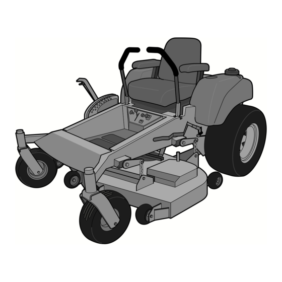
Page 27: Design And Function
Design and Function General The Husqvarna ZTH is a compact, ride-on mower specially designed for mowing large areas of grass. It is operated via two motion control levers and has hydrostatic drive to the rear wheels. Each rear wheel is driven by an independent hydrostatic drive system comprising a hydraulic pump and a hydraulic motor. - Page 28 DESIGN AND FUNCTION The engine identifiers are located on a barcoded decal. This is sited on the left side of the crankcase, directly opposite the starter motor. The decal gives: • The engine code. • The engine number. Quote these when ordeing spare parts. The hydraulic pump identifiers are located on a bardcoded decal.
-
Page 29: Engine
DESIGN AND FUNCTION Engine Husqvarna’s ride-on mowers for professional users have two-cylinder, air-cooled engines from Kawasaki. Major engine repairs are not covered in this workshop manual. Users are referred to Kawasaki’s own manuals. These contain detailed information on the adjustment and repair of the engines. The manuals can be ordered from authorized service workshops. -
Page 30: Mower Deck
DESIGN AND FUNCTION Mower Deck WARNING! The engine must not be started if the operator’s floor plate or any of the guards for the mower deck’s belt is/are not securely in position. The blades are driven by a V-belt from the engine crankshaft (1). -
Page 31: Repairs
Repairs Engine Removing Close the fuel valve. Disconnect the positive cable (red) from the battery. If necessary, drain the motor oil. Disconnect the gas and choke wires from the carburetor. Disconnect the fuel line (with its filter) from the fuel pump. Disconnect the connecting cable (pigtail) from the frame harness connector at the side of the starter motor. - Page 32 Fitting When changing engines, transfer the necessary components to the new engine. The chamfered side of the spacer (3) on the crankshaft above the pump pulley must face the engine. The hub collar of the pulley (5) must face downwards. Put the four upper engine mount isolators (22) in the engine bed (small diameter end in the engine bed hole).
-
Page 33: Adjusting The Throttle Wire
inlet. 14. Connect and adjust the gas and choke wires (see below). 15. Check that the oil drain valve is closed and fill the engine with oil (see Delivery Servicing\Delivery Service). 16. Connect the positive cable (red) to the battery’s positive terminal. 17. -
Page 34: Checking And Adjusting The Choke Wire
the diagram. Pull the throttle wire casing to the far right and tighten the clamping screw. Checking and Adjusting the Choke Wire If the engine produces black smoke or is difficult to start, the choke wire (upper wire) may be incorrectly adjusted. To adjust the choke, proceed as follows: Release the clamping screw that secures the wire casing and set the choke control... -
Page 35: Fuel Tank
Fuel tank Removing Before removing the tank on the right of the mower, the rear wheel and the bolts holding the oil cooler for the hydraulics must be removed. Close the fuel valve (13). WARNING! Fire and health hazard. Avoid spills. Wipe dry if necessary. -
Page 36: Adjusting Motion Control Lever Linkages
Adjusting Motion Control Lever Linkages See “Hydraulic system\Hydraulic pump\Adjusting the linkages”. Adjusting Motion Control Lever Spring-back See “Hydraulic system\Hydraulic pump\Adjusting the Reverse Detent Spring”. Adjusting the Park Brake Raise the rear of the unit and place it on stable jack stands. Engage the parking brake and remove both rear tires/wheels. -
Page 37: Mower Deck
Mower Deck WARNING! No work is to be done on the mower deck or belts until the engine has been rendered incapable of starting. Remove the ignition key or both spark plug cables. Removing Drop the deck as far as it will go and lock the control lever in position with a pin. -
Page 38: Spindle Blade Bearings
Fit the deck’s rear anti-scalp rollers. Attach the chains to the lift arms. Fit the belt as per the routing diagram. Check that the belt is not twisted and that it runs correctly around all the pulleys. Check deck height and horizontality as per “Setting the mower deck”. -
Page 39: Sharpening And Balancing Blades
assembly is supplied with an “O” ring (47) . The “O” ring must be removed before the pulley is fitted. Replacing Bearings The fitting procedure is the reverse of the removal procedure. Tightening torques: • Blade bolts 122 Nm (90 lb/ft). •... -
Page 40: Setting The Mower Deck
Setting the Mower Deck Leveling Position the mower on a level, preferably concrete, surface. Check the pressure in all four tires. This should be 15 psi. Raise the mower on lengths of 2" x 4" placed edgewise under the cutting deck from front to rear (see diagram). - Page 41 Using a 9/16" socket on the bolt of the idler pulley, loosen the deck belt. Roll the belt off the deck pulleys. Roll the belt off the clutch pulley on the crankshaft. Remove the old belt. Fitting the new belt is the reverse of the procedure given above.
-
Page 42: Changing Pump And Deck Belts
Hydraulic Pump Belt Check the belt every 75 to 100 hours of operation. Inspect carefully for large cracks and significant damage. The small cracks that arise from normal use do not make it necessary to change the belt. Changing Pump and Deck Belts Drop the deck to its lowest position. -
Page 43: Front Wheel Bearings
Pump Belt Tensioning Assembly The belt is automatically tensioned by a spring (37). To cancel the force of the spring when removing or fitting the belt, use a 1/2" ratchet wrench in the square hole in the idler arm (45). Check that there is no abnormal noise indicating that the idler pulley is loose on its shaft. - Page 44 REPAIRS English-...
-
Page 45: Electrical System
ELECTRICAL SYSTEM Electrical System Troubleshooting See the “Troubleshooting” section towards the back of this manual. Wiring Assembly The diagram below shows the structure of the electrical system. A. To the engine ground bolt B. To the solenoid C. To the electric clutch ZTH electrical system To connect the engine to the frame harness (13), there is a pigtail. - Page 46 ELECTRICAL SYSTEM The console harness (1) connects the console controls to the frame harness. Blk = Black Blu = Blue Gra = Gray Grn = Green Pur = Purple Wht = White Yel = Yellow ZTH console harness English- 8011-629...
- Page 47 ELECTRICAL SYSTEM There are two connectors connecting the frame harness (13) to the console harness (1). Blk = Black Blu = Blue Gra = Gray Grn = Green Pur = Purple Wht = White Yel = Yellow ZTH frame harness The engine pigtail (page 43) plugs into the “Engine Pigtail”...
-
Page 48: Battery
ELECTRICAL SYSTEM Battery The battery is maintenance-free and the cells are sealed. Breaking the seal invalidates the warranty. To avoid exposing the battery terminals to dangerous stress, use two wrenches when connecting or disconnecting the battery cables. WARNING! The battery contains corrosive acid. Wear goggles. Do not tip the battery over. The battery gives off explosive fumes. -
Page 49: Relays
ELECTRICAL SYSTEM Relays Refer to the “ZTH electrical system” diagram. The relays (22) plug into a holder under the seat (on the left). The three relays are identical and can be plugged into any of the sockets in the holder. Relay function (working along the holder from right to left) is: •... -
Page 50: Ignition And Start Switch
ELECTRICAL SYSTEM Ignition and Start Switch Refer to the “ZTH electrical system” diagram. Changing Free the control console and pull forwards. Disconnect the wires at the back of the ignition switch (10). Remove the ignition key and the rubber cap (20). Remove the nut (19) and the ignition switch (10). -
Page 51: Blade Switch
ELECTRICAL SYSTEM Blade Switch Refer to the “ZTH electrical system” diagram. Changing Free the control console and pull forwards. Disconnect the wires at the back of the switch (11). Push in the plastic catch on the switch’s short side and draw the switch out through the console panel. With the plastic catch and two contact pins facing upwards, push the new switch into the console panel unitl it is correctly seated. -
Page 52: Motion Control Switches
ELECTRICAL SYSTEM Fitting The fitting procerdure is the reverse of the removal procedure. Pay particular attention to the following: • The tightening torque for the bolt (9) is 67 Nm (50 ft/lb). • With the bolt (9) tightened, there should be perceptible play between the clutch and the clutch tie down (10) when the clutch flange is turned by hand. -
Page 53: Park Brake Interlock Switch
ELECTRICAL SYSTEM Removing Swing the seat completely out of the way. Release the mechanical link between the left park brake and the brake lever. Release the dampeners (23) and springs (17) from the tubular shafts (31, 33) by removing the bolts (16) - each with two nuts (22) - spacers (21) and washers (11). -
Page 54: Welding
ELECTRICAL SYSTEM Welding The following applies to arc, MIG, TIG and all other electrical welding methods. IMPORTANT INFORMATION When performing electric welding on the mower, take all necessary precautions to prevent damage to the electrical system. The engine’s ignition system has sensitive electrical components. Electrical welding must not, therefore, be carried out on the engine. -
Page 55: Hydraulic System
HYDRAULIC SYSTEM Hydraulic System Hydraulics Hygiene If they are to operate well, hydraulic systems must be kept free from all impurities. During operation, particles that can cause both wear and malfunction are generated inside hydraulic systems. To separate these particles from the hydraulic fluid, filters are used. Filters are dimensioned to cope with particles developed within the system. -
Page 56: Hydraulic Oils
HYDRAULIC SYSTEM Hydraulic Oils The oil is as important as any other part of the hydraulic system. It has been shown that 70% of all problems with hydraulics are due either to the use of unsuitable oil grades or filling/topping-up with contaminated oil. -
Page 57: Zth Hydraulic System
HYDRAULIC SYSTEM ZTH Hydraulic System 8011-588 ZTH hydraulic system The hydraulic pumps are controlled (via mechanical links) by the motion control levers. 8011-589 Hydraulic pump linkages English-... -
Page 58: Hydraulic Tank
HYDRAULIC SYSTEM Hydraulic Tank Draining The drain cap (29) is located on the underside of the tank in the front left corner (see the “ZTH hydraulic system” diagram). Drained hydraulic oil must be handled in accordance with the regulations governing the disposal of waste oil. -
Page 59: The Cooler For The Hydraulic System
The fitting procedure is the reverse of the removal procedure. Hydraulic Filter Use genuine Husqvarna filters only. The use of pirate parts can invalidate the warranty. Changing Filters When changing the oil in the hydraulic tank, change the filter also. Dispose of the used filter in accordance with the environmental regulations relating to engine oil filters. -
Page 60: Hydraulic Pump
HYDRAULIC SYSTEM Fitting IMPORTANT INFORMATION Pipes between hydraulic pumps and hydraulic motors must not be subjected to bending or compression. To avoid pipe fatigue and the resultant leaks and fractures, the fitting procedures below must be observed. Clean the surfaces mating pumps and motors to their mounts. Bolt the hydraulic pump loosely into place - it must still be possible to move the pump. - Page 61 HYDRAULIC SYSTEM • Ensure that the pump pulley aligns with the crankshaft pulley and the pulley for the other pump. • Ensure, on both sides, that the link between the motion control lever and the hydraulic pump is correctly adjusted. •...
-
Page 62: Hydraulic Motors
HYDRAULIC SYSTEM Holding the lever, adjust the spring by sliding the bolt (37) in the slot to remove all the slop. Retighten the bolt. Check the adjustment by pulling the motion control lever back to the reverse position and releasing it. If necessary, make the same adjustment on the other side. -
Page 63: Troubleshooting
TROUBLESHOOTING Troubleshooting Engine Check section 8 of the Kawasaki Service Manual. The above section contains a troubleshooting guide for engine and auxiliary systems. It also has a special section on troubleshooting the starter motor. Wiring Harness • Symptom: The starter motor works but the engine does not turn over. Suggested procedure: Check the fuel level and the position of the fuel valve lever. - Page 64 TROUBLESHOOTING to RUN? If yes, the problem is probably in the engine harness, engine components or ignition switch. Disconnect the fuel valve. If the fuse does not blow, the problem is probably in the fuel valve. If, from point 1 above, the fuse does not blow, reattach the hour meter connectors. If the fuse blows, the hour meter is probably faulty.
-
Page 65: Clutch
TROUBLESHOOTING Clutch • Measuring clutch coil resistance. Turn the engine and PTO switch off. Disconnect the clutch at the clutch connector. Set the meter to read ohms. Connect the meter leads to the clutch. Check the meter reading. CMS-175 (237 Nm) = 2.45 - 2.71 Ω. CMS-200 (271 Nm) = 1.74 - 1.93 Ω. - Page 66 TROUBLESHOOTING Problem Possible causes Clutch will not engage Blown fuse. • Low coil resistance. • Defective battery. • Faulty charging system. • Bad wiring or connections, PTO switch Low voltage supply. • Defective battery. • Faulty charging system. • Bad wiring or connectors, PTO switch.
- Page 67 TROUBLESHOOTING Overloaded clutch. • Clogged deck, faulty spindle, etc. Contaminated friction • Engine oil leak on clutch. surfaces. Noisy clutch/vibrations Failed bearing. • Loose mounting (bolt not tightened to the correct torque). • Insufficient play at the adapter plate Adapter plate rattles •...
-
Page 68: Hydraulic Pump
TROUBLESHOOTING Hydraulic Pump In most cases, problems with the drive system are not due to a defective pump but to slipping drive belts, partially engaged bypass valves, loose or damaged control linkages, etc. Be sure to check all of these before assuming a pump is faulty.The troubleshooting checklist below is designed to help determine the cause of problems. - Page 69 TROUBLESHOOTING • Bypass loose. • Inlet leak. • Clogged/damaged hydraulic filter. • Defective hydraulic pump. Unit operating hot. • Build-up of of grass cuttings. • Hydraulic cooler clogged or damaged. • Oil level low or oil contaminated. • Excessive loading (long grass). •...
- Page 70 ´+H("¶6D¨...
- Page 71 Svenska –...
- Page 72 114 00 80-26 ´+H("¶6D¨ 2002W20...
- Page 73 We hope you find the links below useful. For further gardening information visit Blower Vacs Brush cutters Cultivators Cylinder lawn mowers Electric Fertiliser chainsaws spreaders Garden tractors Garden vacuums Hover mowers Husqvarna chainsaws Lawn scarifiers Lawn tractors Petrol hedge Ride on lawn cutters mowers Ryobi strimmers Scarifiers Westwood Brush Cutters tractors...