
Related Manuals for Husqvarna 13 AWD


Summary of Contents for Husqvarna 13 AWD
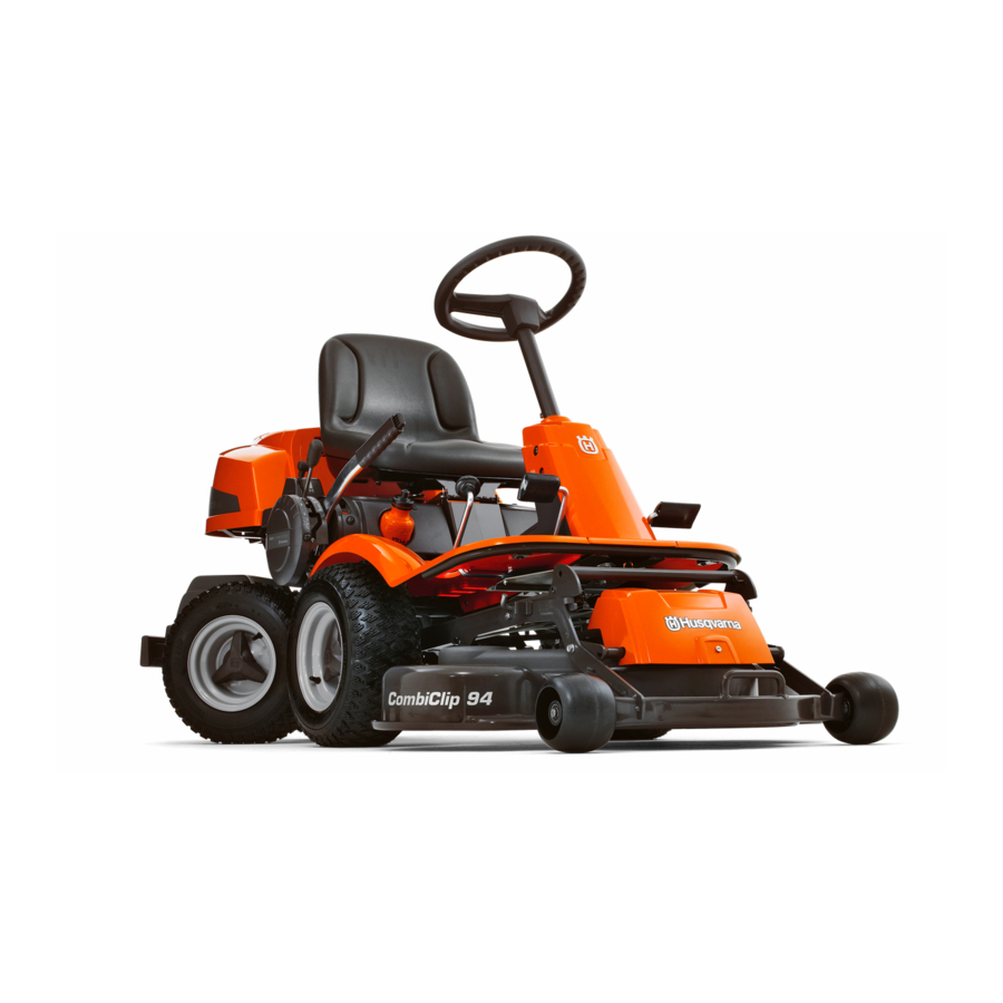
- Page 1 Operator´s manual Rider 11 Rider 11 C Rider 13 C Rider 13 AWD Rider 15 C Please read these instructions carefully and make sure English you understand them before using the machine.
-
Page 3: Table Of Contents
Rider 13 C, Rider 13 AWD and Rider 15 C Introduction ... 2 Driving and transport on public roads ... 2 Towing ... 2 Use ... 2 Serial number ... 3 Explanation of symbols ... 4 Safety Instructions ... 5 General Use ... -
Page 4: Introduction
INTRODUCTION Dear customer Thank you for choosing a Husqvarna Rider. Husqvarna Riders are built to a unique design with a front- mounted cutting unit and a patented rear-wheel steering system. Riders are designed for maximum efficiency even in small or confined areas. The closely grouped controls and pedal-operated hydrostatic transmission (certain models) also contribute to the performance of this machine. -
Page 5: Serial Number
Good service Husqvarna products are sold all over the world and only through servicing dealers. This is to ensure that you, the customer, get the best support and service. Before the machine is delivered it undergoes inspection and is adjusted by your dealer. -
Page 6: Explanation Of Symbols
EXPLANATION OF SYMBOLS These symbols are on the machine and in the operator’s manual. Study them carefully so that you know what they mean. Reverse Neutral Fast Oil pressure Cutting height Use hearing protection Clutch in Noise emission to surround- Warning! Rotating blades. -
Page 7: Safety Instructions
SAFETY INSTRUCTIONS Safety instructions These instructions are for your safety. Read them carefully. WARNING! The inserted symbol means that important safety instructions need to be observed. It applies to your safety. General use • Read all the instructions in this operator’s manual and on the machine before you start it. - Page 8 SAFETY INSTRUCTIONS • Take care when rounding a fixed object, so that the blades do not hit it. Never run the machine over foreign objects. • Only use the machine in daylight or in other well-lit conditions. Keep the machine at a safe distance from holes or other irregularities in the ground.
-
Page 9: Driving On Slopes
SAFETY INSTRUCTIONS Driving on slopes Driving on slopes is one of the operations where the risk of the driver losing control of the machine or of it overturning is the greatest; this can result in serious injury or death. All slopes demand extra care. -
Page 10: Children
SAFETY INSTRUCTIONS Children • Serious accidents may occur if you fail to be on your guard for children in the vicinity of the machine. Children are often attracted to the machine and mowing. Never assume that children will remain where you last saw them. •... - Page 11 SAFETY INSTRUCTIONS • If leaks arise in the fuel system, the engine must not be started until the problem has been resolved. • Store the machine and fuel in such a way that there is no risk that leaking fuel or fumes can cause any damage.
-
Page 12: Transport
SAFETY INSTRUCTIONS • Never use the machine indoors or in spaces lacking proper ventilation. Exhaust fumes con- tain carbon monoxide, an odourless, poisonous and highly dangerous gas. • Stop and inspect the equipment if you run over or into anything. If necessary, make repairs before starting. -
Page 13: Presentation
Parking brake on 13 C, 13 AWD and 15 C Clutch pedal on 11 and 11 C PRESENTATION On the Rider 13 C, Rider 13 AWD and Rider 15 C the power transmission from the engine is handled by a hydrostatic gearbox which enables stepless variation of the speed. -
Page 14: Clutch Pedal Rider 11, 11 C
PRESENTATION RIDER 11, 11 C Throttle and Choke lever The engine speed is adjusted with the throttle control, and thereby also the rotation speed of the blades. The control is also used to activate the choke function. When the choke is used the engine receives a richer mixture of fuel and air, which simplifies cold start. -
Page 15: Throttle/Choke Lever Rider 13, 13 Awd, 15 C 13 Speed Limiter Rider 13, 13 Awd, 15 C
PRESENTATION RIDER 13 C, 13 AWD, 15 C Throttle and Choke lever The engine speed is adjusted with the throttle control, and thereby also the rotation speed of the blades. The control is also used to activate the choke function. When the choke is used the engine receives a richer mixture of fuel and air, which simplifies cold start. -
Page 16: Cutting Unit
Rider 11 has a cutting unit with rear ejection, i.e. the grass cuttings are thrown out behind the cutting unit. Rider 11 C, Rider 13 C, Rider 13 AWD and Rider 15 C have a 3-blade BioClip cutting unit. Lift lever for cutting unit The lift lever is used to set the cutting unit in trans- port or cutting position. -
Page 17: Lever For Adjustment Of Cutting Height
Lever for adjustment of cutting height With this lever the cutting height can be adjusted to 9 different positions. Cutting unit with rear ejection, Combi-unit, Seat The seat has a jointed attachment on the front edge and can be tipped forward. The seat can also be adjusted lengthways. -
Page 18: Driving
The parking brake lock disconnects automati- cally when the brake pedal is pressed down. Rider 13 AWD The engine can not be started if the parking brake is not pressed down. On the Rider 11 and Rider 11 C the brake pedal and lock button are on the right side. - Page 19 Cold engine: 4. Push the throttle control to position 3 (choke position). In this position the engine receives a richer mixture so that the engine starts more easily. The throttle must be moved to the side (towards the ignition key) to reach the choke position. Warm engine: 5.
-
Page 20: To Start An Engine With A Weak Battery
7. When the engine has started release the igni- tion key to neutral position. Push the throttle control to the required speed. For cutting 3/4 to full throttle. WARNING! Never run the engine indoors, in enclosed or poorly ventilated areas. The exhaust fumes contain toxic carbon monoxide. -
Page 21: Driving The Machine
Driving the machine 1. Release the parking brake by pressing down the brake pedal. 2. For Rider 13 C, Rider 13 AWD and Rider 15 C Carefully press down one of the pedals until the correct speed is reached. To drive forwards: press down pedal (1). -
Page 22: Cutting Tips
3. Select the required cutting height (1-9) with the cutting height lever. To obtain a uniform cutting height it is important that the tyre pressures are equal on both front wheels 60 kPa (8.5 PSI). 4. Push in the lock button on the lift lever and lower down the cutting unit. -
Page 23: Stopping The Engine
WARNING! Never drive the machine on ground with a slope of more than 15°. Mow slopes upwards and downwards, never across. Avoid sudden changes in direction. Hill start, manual gearbox 1. Press down the parking brake. 2. Push the throttle control to full throttle position. 3. -
Page 24: Drive Disengagement Lever
Release lever Rider 13 AWD Rider 13 AWD has one control for the front axle and one control for the rear axle. Pull the controls to their end positions. Do not use an intermediate position. -
Page 25: Maintenance
Adjust the brakes Rider 11 and Rider 11 C Check the V-belts Check the transmission’s cooling flanges Rider 13 C, Rider 13 AWD and Rider 15 C Check the transmission’s oil level Rider 13 C, Rider 13 AWD and Rider 15 C... -
Page 26: Cleaning
Cleaning Clean the machine directly after use. It is much easier to wash off grass cuttings before they dry. Oily dirt can be removed using a cold degreasing agent. Spray on a thin layer. Rinse at normal water pressure. Do not direct the jet towards electrical components or bearings. -
Page 27: Dismantling Of The Machine Hoods
Front hood Rider 11 Release the screws in the front hood (3) and lift off the hood. Front hood Rider 11 C, Rider 13 C, Rider 13 AWD and Rider 15 C Release the catch and lift off the hood. -
Page 28: Inspecting The Silencer
Right-hand fender Remove the screws (2 and 3) from the fender. On the Rider 13 C, Rider 13 AWD and Rider 15 C the knob (1) must also be removed. Left-hand fender Release the screws in the fender and lift off the fender. -
Page 29: Checking And Adjusting The Steering Wires
Checking and adjustment of the steering wires The steering is controlled by means of wires. These can in time become slack, which implies that the adjustment of the steering becomes altered. Check and adjust the steering as follows: 1. Dismantle the frame-plate by releasing the screws (two on each side). -
Page 30: Checking And Adjusting The Brakes
Checking the brake Rider 11 and Rider 11 C The brake is of the disc brake type and is fitted on the gearbox. Check that the brake is correctly adjusted by measuring the distance between the brake lever and the front edge of the recess on the chassis. The distance should be 0–1 mm (0-0.040") when the brake is not applied. - Page 31 Adjusting the Parking Brake Rider 13 AWD Check that the parking brake is adjusted correctly by placing the machine on a slope with the front and rear axles disengaged. Apply and lock the parking brake. When the machine does not stand still, the parking brake should be adjusted accord- ing to the following.
-
Page 32: Checking And Adjustment Of Throttle Wire
Adjustment of the throttle wire If the engine does not respond as it should when the throttle lever is moved, or if it produces black smoke or does not reach top speed, the throttle wire may need adjusting. 1. Release the clamping screw (see arrow) and push the throttle control to the choke position. -
Page 33: Replacement Of Air Filter
Replacing the air filter If the engine seems to lack power or goes irregu- larly the reason may be that the air filter is clogged. It is therefore important to replace the air filter at regular intervals (see ”Maintenance \ Maintenance Schedule”... -
Page 34: Checking The Fuel Pump's Air Filter
Checking of the fuel pump’s air filter Check regularly that the fuel pump’s air filter is free from dirt. The filter can when necessary be cleaned with a brush. Check the level of the battery acid Check that the level of the battery acid lies between the markings. -
Page 35: Checking The Safety System
Inspecting the safety system The Rider is equipped with a safety system that prevents starting or driving under the following conditions: The engine should only be possible to start when the cutting unit is in its raised position and the hydrostat pedals are in the neutral position. - Page 36 Check that the engine stops if you temporarily move out off the driver’s seat while the cutting unit is lowered or the hydrostat pedals are not in the neutral position. Startmotor Ignition system Rider 13 AWD Works Does not work 8009-153...
-
Page 37: Main Fuse
Main fuse The fuse is located in a loose holder under the battery case cover, in front of the battery. Type: Flat-blade mounting, 15 A. Do not use any other type of fuse when replacing. A blown fuse indicates that the mounting has burnt off. -
Page 38: Checking And Adjusting The Cutting Unit Ground Pressure
Checking and adjustment of the cutting unit’s ground pressure on Rider 11 C, Rider 13 C, Rider 13 AWD and Rider 15 C To achieve the best cutting results the cutting unit should follow the underlying surface without press- ing too hard against it. -
Page 39: Adjusting The Parallelism Of The Cutting Unit
7. Fit the right-hand fender and the front hood. Adjusting the parallelism of the Cutting deck on Rider 11 C, Rider 13 C, Rider 13 AWD, Rider 15 C Check that the tyres’ air pressure is 60 kPa (0.6 kp/cm /8.5 PSI). -
Page 40: Service Position For The Cutting Unit
MAINTENANCE RIDER 11C,13C, 13 AWD,15C Service position for BioClip 90 The cutting head can be placed in the service position to provide easy access for cleaning, repairs and servicing. In the service position the cutting unit is raised and locked in the vertical position. - Page 41 MAINTENANCE RIDER 11C,13C, 13 AWD,15C 4. Fit the support wheels on either side of the rear of the cutting unit. WARNING! Wear protective glasses when dismantling the cutting unit. The spring which tensions up the belt can go off and cause personal injury.
- Page 42 MAINTENANCE RIDER 11C,13C, 13 AWD,15C WARNING! Take care not to get your hand trapped. 8. Lift off the drive belt (1). Then pull out the pin (2). 9. Pull the frame forwards and refit the pin. 10. Grasp the front edge of the cutting unit, pull out and raise into the service position.
-
Page 43: Checking The Blades
Checking the blades To achieve the best mowing results it is important that the blades are undamaged and well-sharpened. Check that the blades’ attachment screws are tight. IMPORTANT INFORMATION Replacing or sharpening the blades should be conducted by an authorised service workshop. -
Page 44: Lubrication
Check the engine’s oil level Check the oil level in the engine when the Rider stands horizontal with the engine switched off. Check the oil level in the engine when the machine is horizontal. Raise the engine cover. Release the dip stick and pull out. Wipe off the oil and insert again. -
Page 45: Checking The Transmission's Oil Level
Check the transmission’s oil level Rider 13 C, Rider 13 AWD and Rider 15 C 1. Lift off the transmission cover. Release the two screws (one of each side) and lift off the trans- mission cover. 2. Rider 13 C, Rider 15 C Check that there is oil in the transmission oil tank. -
Page 46: General Lubrication
Lubrication Rider 11 and Rider 11 C Lubrication of front wheel bearings On Riders with rear ejection the hood and wings must be removed so that the bar can be raised to allow removal of the wheel. 1. Remove the plastic cover on the hub. 2. -
Page 47: Trouble Shooting Schedule
TROUBLE SHOOTING SCHEDULE Problem Engine will not start Starter does not pull round engine Engine does not run smoothly Engine seems to have no power Engine overheats Battery does not charge Machine vibrates Uneven mowing Procedure • Fuel tank empty •... -
Page 48: Storage
Winter storage At the end of the season the machine should immediately be put in order for storage, also if it is going to stand idle for more than 30 days. Fuel which is left to stand for long periods (30 days or more) can leave tacky deposits which can block the carburettor and interfere with the engine. -
Page 49: Technical Data
Dimensions Rider 11 Length without unit Length with unit 2040 mm / 6.69 ft Width without unit Width with unit 960 mm / 3.15 ft Height 1070 mm / 3.52 ft Weight in working order with unit 229 kg / 505 lb Wheel base 820 mm / 2.69 ft Track... - Page 50 When this product is worn out or no longer used it should be returned to the dealer or other appropriate body for recycling. – English TECHNICAL DATA / 8.5 PSI) Rider 13 AWD 2010 mm / 6.58 ft 2220 mm / 7.29 ft 880 mm / 2.89 ft 1114 mm / 3.65 ft 1070 mm / 3.52 ft...
- Page 51 Dimensions Rider 15 C Length without unit 2010 mm / 6.58 ft Length with unit 2220 mm / 7.29 ft Width without unit 880 mm / 2.89 ft Width with unit 1114 mm / 3.65 ft Height 1070 mm / 3.52 ft Weight in working order with unit 249 kg / 549 lb...
-
Page 52: Eu Declaration Of Conformity
Husqvarna AB, SE-561 82 Huskvarna, Sweden, tel: +46-36-146500, declares under sole responsibility that Husqvarna Rider 11, Rider 11 C, Rider 13 C, Rider 13 AWD and Rider 15 C, from 2005’s serial numbers and onwards (the year is clearly stated in plain text on the rating plate with subsequent serial number), complies with the requirements of the COUNCIL’S DIRECTIVES:... - Page 53 Work done Pre-delivery service 1. Top up battery with acid and recharge for four hours. 2. Fit steering wheel, seat and any optional equipment. 3. Adjust cutting unit: Adjust the lifting springs (the ”weight” of the cutting unit should be 12-15 kg). Only applies to BioClip. Adjust cutting unit so that rear edge is about 2–4 mm higher than front edge.
- Page 54 SERVICEJOURNAL Date, mileage, stamp, sign Work done – English ´®z+R-h¶6D¨...
- Page 55 English –...
- Page 56 115 01 37-26 ´®z+R-h¶6D¨ 2005W46...