
Related Manuals for Husqvarna 11/13 H


Summary of Contents for Husqvarna 11/13 H
- Page 1 Rider 11/13 H Operator´s manual Please read these instructions carefully and make sure you understand them before using the machine. 101 90 52-95...
- Page 2 Svenska –...
-
Page 3: Table Of Contents
Rider 11 and Rider 13 H Explanation of symbols ... 2 Safety instructions ... 3 General operation ... 3 Slope operation ... 3 Children ... 3 Service ... 4 Travel and transport on public roads ... 4 Towing ... 4 Intended use ... -
Page 4: Explanation Of Symbols
EXPLANATION OF SYMBOLS These symbols are on the machine and in the operator’s manual. Study them carefully so that you know what they mean. Reverse Neutral Fast Oil pressure Cutting height Use eye and Clutch in hearing protection Soundlevel Warning! Rotating blades. -
Page 5: Safety Instructions
SAFETY INSTRUCTIONS These instructions are for your safety. Read them carefully. Safe operation practices for ride-on mowers IMPORTANT! This cutting machine is capable of amputating hands and feet and throwing objects. Failure to ob- serve the following safety instructions could result in serious injury or death. General operation 1. -
Page 6: Iv. Service
SAFETY INSTRUCTIONS IV. Service 1. Use extra care in handling gasoline and other fuels. They are flammable and vapours are explosive. a) Use only an approved container. b) Never remove gas cap or add fuel with the engine running. Allow engine to cool before refuelling. -
Page 7: General Use
SAFETY INSTRUCTIONS This symbol implies that important safety rules are applicable. This is for your safety and the operating reliability of the machine. General use: • Make yourself familiar with the controls and how to stop quickly. • Read all the instructions in Operator’s Manual and on the machine before starting it. -
Page 8: Driving On Slopes
SAFETY INSTRUCTIONS • Watch out for traffic when working close to a road, or crossing one. • Be careful when rounding a fixed object so that the blades do not hit it. Never drive intentionally over a foreign object. • The machine is heavy and can cause very severe crush injuries. -
Page 9: Children
SAFETY INSTRUCTIONS • Do not cut close to edges, ditches or banks. The machine can suddenly tip over if a wheel goes over the edge of a drop or a ditch, or if a bank gives way. • Do not cut wet grass. It is slippery and the tyres can loose their grip so that the machine slides. - Page 10 SAFETY INSTRUCTIONS • Avoid overfilling. If fuel has been spilt on the machine wipe it up and wait until it has evapor- ated before starting the engine. If fuel is spilt on clothes, change them. • Be extra careful when handling battery acid. Spilling acid on the skin can cause severe burn injuries.
-
Page 11: Presentation
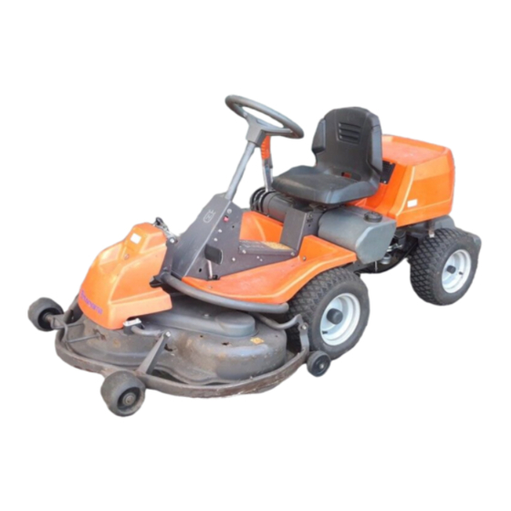
Presentation Congratulation on your choice of a first-class quality product. These instructions describe two models of Rider mower, Rider 11 and Rider 13 H. Both models are fitted with engines from Briggs & Stratton of 10.5 and 12.5 horsepower respectively, plus a cutting unit which throws out grass at the rear of the machine. -
Page 12: Throttle/Choke Lever
PRESENTATION Throttle and Choke lever Rider 13 H The engine speed is adjusted with the throttle control, and thereby also the rotation speed of the blades. The control is also used to activate the choke function. When the choke is used the engine receives a richer mixture of fuel and air, which simplifies cold start. - Page 13 PRESENTATION Throttle and Choke lever Rider 11 The engine speed is adjusted with the throttle control, and thereby also the rotation speed of the blades. The control is also used to activate the choke function. When the choke is used the engine receives a richer mixture of fuel and air, which simplifies cold start.
-
Page 14: Cutting Unit
PRESENTATION Cutting unit Rider 11 and Rider 13 H have a cutting unit with rear ejection, i.e. the grass cuttings are thrown out behind the cutting unit. Lift lever for cutting unit The lift lever is used to set the cutting unit in trans- port or cutting position. -
Page 15: Seat
Seat The seat has a jointed attachment on the front edge and can be tipped forward. The seat can also be adjusted lengthways. Release the wheels under the seat and adjust it forwards or backwards to the required position. Lock the adjustment with the wheels. Fuelling The engine should be run on 85 octane unleaded petrol/gasoline (not oil mixed). -
Page 16: Driving
Before starting • Read the safety instructions and information on the location and function of the controls before starting (see pages 3–13). • Conduct daily maintenance before starting (see maintenance schedule on page 19). Adjust the seat to the required position. Starting the engine 1. - Page 17 Cold engine: 4. Push the throttle control to position 3 (choke position). In this position the engine receives a richer mixture so that the engine starts more easily. Warm engine: 5. Set the throttle control midway between position 1 and 2. 6.
-
Page 18: Driving The Machine
7. When the engine has started release the ignition key to neutral position. Push the throttle control to the required speed. For cutting 3/4 to full throttle. WARNING! Never run the engine indoors, in enclosed or poorly ventilated areas. The exhaust fumes contain toxic carbon monoxide. -
Page 19: Cutting Tips
3. Select the required cutting height (1-9) with the cutting height lever. To obtain a uniform cutting height it is important that the tyre pressures are equal on both front wheels (60 kPa). 4. Push in the lock button on the lift lever and lower down the cutting unit. -
Page 20: Stopping The Engine
WARNING! Never drive the machine on ground with a slope of more than 15°. Mow slopes upwards and downwards, never across. Avoid sudden changes in direction. Hill start, manual gearbox 1. Press down the parking brake. 2. Push the throttle control to 3/4 position to full throttle position. -
Page 21: Maintenance
The following is a list of the maintenance which should be conducted on the machine. For the items which are not described in these instructions go to an authorised service workshop. Maintenance Check the engine’s oil level Check the engine’s cooling air inlet Check the fuel pump’s air filter Check the steering wires Check the brakes... -
Page 22: Dismantling Of The Machine Hoods
MAINTENANCE Dismantling of the machine hoods Engine hood The engine is accessible for servicing when the engine hood is lifted up. Tilt the seat forward, release the rubber strap under the seat, and tilt the hood backwards. Front hood Release the screws in the front hood (3) and lift off the hood. -
Page 23: Checking The Engine's Oil Level
MAINTENANCE Check the engine’s oil level Check the oil level in the engine when the machine is horizontal. Raise the engine cover as described on page 18. Release the dip stick and pull out. Wipe off the oil and insert again. The dip stick must be fully screwed down. -
Page 24: Checking And Adjusting The Steering Wires
Checking and adjustment of the steering wires The steering is controlled by means of wires. These can in time become slack, which implies that the adjustment of the steering becomes altered. Check and adjust the steering as follows: 1. Dismantle the frame-plate by releasing the screws (two on each side). -
Page 25: Adjusting The Brake
Checking the brake Rider 11 The brake is of the disc brake type and is fitted on the gearbox. Check that the brake is correctly adjusted by measuring the distance between the brake lever and the front edge of the recess on the chassis. The distance should be 0–1 mm when the brake is not applied. -
Page 26: Checking The Transmission's Oil Level
Check the transmission’s oil level Rider 13 H 1. Check the transmission’s oil level by removing the transmission cover. Release the two screws (one of each side) and lift off the transmission cover. 2. Unscrew the oil cap and check that the oil level lies between the markings on the dip stick. -
Page 27: Replacement Of Air Filter
Replacing the air filter If the engine seems to lack power or goes irregu- larly the reason may be that the air filter is clogged. It is therefore important to replace the air filter at regular intervals (see maintenance schedule on page 19 for correct service interval). -
Page 28: Checking The Parallelism Of The Cutting Unit
Checking the cutting unit’s parallelism Check the parallelism of the cutting unit as follows: 1. Place the machine on a level surface. 2. Measure the distance from the ground to the edge of the unit, at the front and back of the hood. -
Page 29: Dismantling The Cutting Unit
Dismantling the cutting unit The cutting unit can be released from the machine for cleaning or checking of the blades and screws. Dismantle the cutting unit as follows: 1. Dismantle the front hood and right-hand and left- hand fenders as described on page 20. 2. -
Page 30: Checking The Blades
Checking the blades To achieve the best mowing results it is important that the blades are undamaged and well-sharpened. Check that the blades’ attachment screws are tight. IMPORTANT INFORMATION Replacing or sharpening the blades should be conducted by an authorised service workshop. -
Page 31: Changing The Oil
Changing the oil The oil should be changed for the first time after 5 hours of running time. Thereafter it should be changed every 25 hours of running time. WARNING! Engine oil can be very hot if it is drained off directly after the engine is stopped. - Page 32 MAINTENANCE Lubrication The following two lubrication points should be regularly lubricated with high quality graphite grease. With daily use lubrication should be conducted twice a week. General lubrication All joints and bearings are lubricated on manufac- ture with molybdenum sulphide grease. Re-grease with same type of grease.
-
Page 33: Checking And Adjustment Of Throttle Wire
Checking and adjustment of the throttle wire If the engine does not respond as it should do when the throttle lever is moved or if the top speed is not reached, the throttle wire may need adjusting. 1. Release the clamping screw (see arrow) and push the throttle control to full throttle position. -
Page 34: Trouble Shooting Schedule
TROUBLE SHOOTING SCHEDULE Problem Engine will not start. Starter does not pull round engine. Engine does not run smoothly. Engine seems to have no power. Engine overheats. Battery does not charge. Machine vibrates. Uneven mowing. – English Procedure • Fuel tank empty. •... -
Page 35: Storage
Winter storage At the end of the season the machine should immediately be put in order for storage, also if it is going to stand idle for more than 30 days. Fuel which is left to stand for long periods (30 days or more) can leave tacky deposits which can block the carburettor and interfere with the engine. -
Page 36: Technical Data
Dimensions Rider 11 Length 2000 mm Width 960 mm Height 1060 mm Unladen weight 225 kg Wheel base 820 mm Track 610 mm Tyre size 16 x 6.50 x 8 Tyre pressure, front & rear 60 kPa (0.6 kp/cm Max. gradient 15°... - Page 37 We, Husqvarna AB, S-561 82 Huskvarna, Sweden, tel. +46 36-146500, declare under sole responsibility that the rider mowers Husqvarna Rider 11/13 H from 1998’s serial numbers and onwards (the year is clearly stated in plain text on the type plate with subsequent serial number), is in conformity with the following standards or other normative documents following the provisions in the COUNCIL’S DIRECTIVES:...
- Page 38 – English ´*3%=¶5v¨...
- Page 39 English –...
- Page 40 ´*3%=¶5v¨ 1999W43...