Table of Contents
Advertisement
Quick Links
Advertisement
Table of Contents

Related Manuals for Husqvarna Rider 11 R


Summary of Contents for Husqvarna Rider 11 R
- Page 1 Oper ator ′ s manual Rider 11 R Rider 11 C Rider 13 C Rider 16 C AWD Rider 16 C Please r ead the operator’s manual carefully and make sure you E E E E n n n n g g g g l l l l i i i i s s s s h h h h...
-
Page 2: Table Of Contents
Cleaning ............... Removing of the machine hoods ......... Checking and adjusting the steering wires ....Checking the brake Rider 11 R and Rider 11 C ... Adjusting the brake ............Adjusting the parking brake ......... Adjusting the parking brake ......... -
Page 3: Intr Oduction
Dear Customer , Thank y ou for choosing a Husqvarna Rider. Husqvarna Riders are built to a unique design with a front-mounted cutting unit and a patented rear-wheel steering system. Riders are designed for maximum efficiency even in small or confined areas. The closely grouped controls and pedal-operated hydrostatic transmission also contribute to the performance of this machine. -
Page 4: Ser Vice Journal
Ser vice journal Pre-deliver y service 12 Tell customer about: Needs and benefits of following the service 1 Charge the battery for 4 hours at max. 3 amp. schedule. 2 Fit steering wheel, seat and any optional Servicing and the influence of this journal on the equipment. -
Page 5: Key To Symbols
KEY T O SYMBOLS Symbols Ignition These symbols are on the machine and in the instr uctions. Hydrostatic freewheel WARNING! Careless or incorrect use can result in serious or fatal injury to the operator or others. Warning: rotating parts. Keep hands and feet clear. - Page 6 KEY T O SYMBOLS The cutting dec k must be fitted at full speed. Starting instructions Check the engine’s oil level Check the hydrostat’s oil level Lift up the cutting unit Apply and lock the parking brake. If the engine is cold, use the choke Release the parking brake before driving Switch off the engine and take off the ignition cable before repairs or maintenance...
-
Page 7: Safety Instr Uctions
SAFETY INSTR UCTIONS Saf ety instructions • Stop the engine and prevent the engine from being started until you have cleaned the outlet channel. These instr uctions are for your safety. Read them carefully. • Look out for the ejector and do not direct it towards anyone. -
Page 8: Driving On Slopes
SAFETY INSTR UCTIONS This is what y ou do • Never allow children or other persons not trained in the use of the machine to use or service it. Local laws may • Remove obstacles such as stones, branches, etc. regulate the age of the user. -
Page 9: Children
SAFETY INSTR UCTIONS • Follow the manufacturer’s recommendations regarding • Petrol and petrol fumes are poisonous and extremely wheel weights or counterbalance weights to increase flammable. Be especially careful when handling petrol, as machine stability. carelessness can result in personal injury or fire. •... -
Page 10: Transport
SAFETY INSTRUCTIONS • Take care with battery maintenance. Explosive gases • Reduce the risk of fire by removing grass, leaves and form in the battery. Never perform maintenance on the other debris that may have fastened on the machine. battery while smoking or in the vicinity of open flames or Allow the machine to cool before putting it in storage. -
Page 11: What Is What
WHAT IS WHAT? Location of the controls 1 Throttle control/choke control 9 Lock button for the parking brake, left side on 13 C, 13 AWD and 16 C, right-hand side on 11 and 11 C. 2 Ignition lock 10 Seat adjustment. 3 Gear shift lever, 11 and 11 C 11 Product and serial number plate 4 Cutting height adjustment lever... -
Page 12: Presentation
PRESENTATION Presentation Parking brake The parking brake is applied as follows: Congratulations on your choice of an excellent quality product that will give you great pleasure for many years. Five models equipped with engines from Briggs & Stratton are described in this operator’s manual. -
Page 13: Cutting Unit
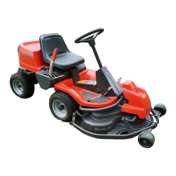
PRESENTATION Cutting unit Cutting height adjustment lever Rider 11 R has a cutting unit with rear ejection, i.e. clippings The cutting height can be adjusted to 7 different positions with are thrown behind the cutting unit. the cutting height lever. -
Page 14: Release Lever
PRESENTATION Release lever Rider 13 C, Rider 16 C The release control must be pulled out in order for the machine to be moved when the engine is shutoff. Pull the controls to the end positions, do not use an intermediate position. -
Page 15: Driving
Driving Before starting - Release the brake pedal while holding the button pressed. The parking brake lock disengages automatically when the brake pedal is pressed. IMPORTANT! Rider 11R and Rider 11 C have the brake pedal and release The air intake grille in the engine cover behind the driver’s button on the right-hand side. -
Page 16: Starting The Engine With A Weak Battery
Driving Connecting the jump leads 7 Turn the ignition key to the start position. IMPORTANT INFORMATION If the engine does not start, wait about 15 seconds before trying again. If the engine does not start wait about 1 minute before trying again. 8 When the engine starts release the ignition key immediately back to neutral position. -
Page 17: Cutting Tips
Driving 3 For Rider 11 R and Rider 11 C 5 Press in the lock button on the lifting lever and lower the cutting unit. Disengage the engine and select the required gear. IMPORTANT INFORMATION The life span of the drive belts is increased significantly if... -
Page 18: Starting On A Slope, Manual Gearbox. (Rider 11 R And Rider 11 C)
1 Lift up the cutting unit by pulling the lever backwards to its locked position. 2 For Rider 11 R and Rider 11 C Pull back the throttle and move the gear shift lever to the neutral position ”N”, without pressing in the reversing lock button. Turn the ignition key to the ”STOP”. -
Page 19: Maintenance
Check the air pressure in the tyres, 60 kPa/8.5 PSI. Lubricate the belt adjuster Lubricate joints and shafts Adjust the brakes Rider 11 R and Rider 11 C Check the V-belts Check the transmission’s cooling fins Rider 13 C, Rider 16 AWD... -
Page 20: Cleaning
Maintenance Cleaning Front cover Release the clip on the front hood and lift off the fender. Clean the machine directly after use. It is much easier to wash off grass cuttings before they dry. Right-hand fender Oily dirt can be removed using a cold degreasing agent. Remove the screws holding the wing cover (2 and 3). -
Page 21: Checking The Brake Rider 11 R And Rider 11 C
WARNING! A poorly adjusted brake can as per item 2. result in reduced braking ability. Checking the brake Rider 11 R and Adjusting the parking brake Rider 16 Rider 11 C The brake is a disc brake and is located on the gearbox. -
Page 22: Adjusting The Throttle Wire
Maintenance 3 Tighten the locking nuts (1). 2 Pull up the handle on the air filter cover, unhook and turn towards the engine. 4 The brake should be checked again after adjustment 5 Assemble the left-hand wing cover. WARNING! A poorly adjusted parking brake can result in reduced braking ability. -
Page 23: Replacement Of Fuel Filter
Maintenance Replacement of fuel filter IMPORTANT INFORMATION Replace the fuel filter every 100 running hours (once per Fitting the wrong spark plug type can damage the engine. season) or more frequently if it is clogged. Replacing the spark plug 1 Remove the ignition cable shoe and clean around the spark plug. -
Page 24: Check The Safety System
Maintenance Check the safety system Start motor The machine is equipped with a safety system that prevents starting or driving under the following conditions. Ignition system The engine should only be possible to start when the cutting unit is in its raised position and the gear shift lever or hydrostat pedals are in the neutral position. - Page 25 Maintenance Rider 16 AWD – 25 English...
-
Page 26: Checking The Engine's Cooling Air Intake
Maintenance Checking the engine’s cooling air 3 Adjust the cutting unit’s ground pressure by screwing the adjuster screws, which are located behind the front intake wheels on both sides, in or out. The ground pressure should be between 12 and 15 kg and the springs evenly Clean the air intake grille in the engine cover behind the tensioned. -
Page 27: Service Position For The Cutting Unit
Maintenance 6 On completion of the adjustment the unit’s parallelism 5 Lift off the drive belt and hang on the load-relieving hook. should be re-checked. 7 Fit the front cover. Service position for the cutting unit The cutting head can be placed in the service position to provide easy access for cleaning, repairs and servicing. -
Page 28: Checking The Blades
Fit the BioClip plug in the reverse order. • Put the unit in the service position, see Service position for the cutting unit. Rider 11 R • Lift up the cutting unit • Set the cutting height control in the highest position. -
Page 29: Lubrication
Lubrication Checking the engine’s oil level. 4 Fit the drain plug and tighten it. 5 Fill with oil up to the ”FULL” mark on the dipstick The oil is Check the oil level in the engine when the Rider stands topped up through the hole the dipstick sits in. -
Page 30: Lubricating The Belt Adjuster
With daily use, lubrication should be carried out twice weekly. Lubrication Rider 11 R and Rider 11 Lubricating the front wheel bearings The front cover and wing covers must be removed on Rider with rear ejection, so that the tubular loop can be lifted to remove the wheel. -
Page 31: Troubleshooting Schedule
Troubleshooting schedule Problem Procedure Engine does not start There is no fuel in the fuel tank Spark plug defective Faulty spark plug connections or interchanged cables Dirt in the carburettor or fuel line Starter motor does not turn over the engine Starter motor does not turn over the engine Battery flat Bad contact between the cable and battery... -
Page 32: Storage
Storage Winter storage Service At the end of the season, or if the machine is going to stand Low season is the most suitable time to perform a service or idle for more than 30 days, it should immediately be made overhaul of the machine in order to ensure high function ready for storage. -
Page 33: Technical Data
TECHNICAL DATA Rider 11 C Rider 13 C Rider 16 AWD Dimensions Length with cutting unit, mm/ft 2220/7,29 2220/7,29 2220/7,29 Width with cutting unit, mm/ft 1000/3,29 1000/3,29 1000/3,29 Height, mm/ft 1070/3,52 1070/3,52 1070/3,52 Operating weight with cutting deck, kg/lb 226/497 232/511 252/556 Wheel base, mm/ft... - Page 34 TECHNICAL DATA Rider 16 C Dimensions Length with cutting unit, mm/ft 2220/7,29 Width with cutting unit, mm/ft 1000/3,29 Height, mm/ft 1070/3,52 Operating weight with cutting deck, kg/lb 232/511 Wheel base, mm/ft 887/2,9 Track width, front, mm/ft 712/2,34 Track width, rear, mm/ft 627/2,06 Tyre dimensions 165/60-8...
-
Page 35: Ec-Declar Ation Of Conformity
EC-declaration of conformity (Applies to Europe only) Husqvarna AB, SE-561 82 Huskvarna, Sweden, tel.: +46-36-146500, hereby declares that Husqvarna Rider 11 R, Rider 11 C, Rider 13 C, Rider 16 AWD and Rider 16 C from 2010’s serial numbers and onwards (the year is clearly stated in plain text on the rating plate with subsequent serial number), complies with the requirements of the COUNCIL’S DIRECTIVE:... - Page 36 Original instructions 1151019-26 ´®z+S!|¶6¶¨ ´®z+S!|¶6¶¨ 2010-02-12...