Table of Contents
Advertisement
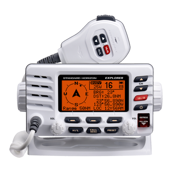
EXPLORER GX1600E
25 Watt VHF/FM
Marine Transceiver
Owner's Manual
Ultra slim and compact rear case design (90 mm depth)
Meets ITU-R M493-13 Class D DSC (Digital Selective Calling)
Oversized full dot matrix display
Automatically poll the GPS position of up to 4 ships using DSC
Enter, Save, and Navigate to Waypoints with the Compass page
GPS information(LAT/LON, SOG, and COG) information shown on the LCD
Submersible JIS-8 1.5 m for 30 minutes
Noise canceling microphone with channel UP/DOWN, 16/9 and H/L keys
Programmable Scan, Priority Scan, and Dual Watch
Programmable soft keys
RAM3 Remote Access Microphone capable
Intercom between radio and RAM3 microphone
NMEA 0183 Input and Output
Die-cast chassis
E2O (Easy to Operate)
When connected to an optional GPS
Advertisement
Table of Contents

Related Manuals for Standard Horizon Explorer GX1600E


Summary of Contents for Standard Horizon Explorer GX1600E
- Page 1 EXPLORER GX1600E 25 Watt VHF/FM Marine Transceiver Owner's Manual Ultra slim and compact rear case design (90 mm depth) Meets ITU-R M493-13 Class D DSC (Digital Selective Calling) Oversized full dot matrix display Automatically poll the GPS position of up to 4 ships using DSC ...
-
Page 2: Table Of Contents
TABLE OF CONTENTS Quick Reference Guide .................... 4 9 DIGITAL SELECTIVE CALLING ..............33 1 GENERAL INFORMATION ................5 GENERAL ....................33 2 PACKING LIST ....................5 MARITIME MOBILE SERVICE IDENTITY (MMSI) ......33 3 OPTIONS ......................5 9.2.1 What is an MMSI? ..............33 4 SAFETY / WARNING INFORMATION ............... - Page 3 TABLE OF CONTENTS 10 ATIS SETUP ..................... 68 14 WAYPOINTS ...................... 88 10.1 ATIS CODE PROGRAMMING ............. 68 14.1 MARKING A POSITION ............... 88 10.2 ATIS CHANNEL GROUP ..............69 14.2 ADDING A WAYPOINT ................ 89 11 GENERAL SETUP ................... 70 14.3 EDITING A WAYPOINT ................
-
Page 4: Quick Reference Guide
UICK EFERENCE UIDE This transceiver is equipped with the E2O (Easy-To-Operate) system. You can do the basic operation in numerical order of the illustration below. Press and hold the button to turn on or off the radio. Rotate the VOL knob to adjust the speaker audio volume. ... -
Page 5: General Information
1 GENERAL INFORMATION The STANDARD HORIZON EXPLOPER GX1600E Marine VHF/FM Marine transceiver is capable of ITU-R 493-13 DSC (Digital Selective Calling) Class D operation. Class D operation allows continuous receiving of Digital Selective Calling functions on channel 70 even if the radio is receiving a call. The GX1600E VHF operate on all currently-allocated marine channels which are switchable for use with International, USA, or Canadian regulations. -
Page 6: Safety / Warning Information
4 SAFETY / WARNING INFORMATION IMPORTANT SAFETY INFORMATION Please read this manual carefully to become familiar with the features of this transceiver before using it for the first time. The installation of this equipment should be made in such a manner as to respect the EC recommended electromagnetic field exposure limits (1999/519/ EC). -
Page 7: Getting Started
5 GETTING STARTED ABOUT VHF RADIO The radio frequencies used in the VHF marine band are between 156 and 162 MHz. The marine VHF band provides communications over distances that are essentially “line of sight” (VHF signals do not travel well through objects such as buildings, hills or trees). -
Page 8: Coaxial Cable
COAXIAL CABLE VHF antennas are connected to the transceiver by means of a coaxial cable – a shielded transmission line. Coaxial cable is specified by it’s diameter and construction. For runs less than 6 m, RG-58/U, about 6 mm in diameter is a good choice. For runs over 6 m but less than 15 m, the larger RG-8X or RG-213/U should be used for cable runs over 15 m RG-8X should be used. -
Page 9: Calling Another Vessel (Channel 16 Or 9)
7. Estimate the present seaworthiness and condition of your vessel. 8. Give your vessel’s description: length, design (power or sail), color and other distinguishing marks. The total transmission should not exceed 1 minute. 9. End the message by saying “OVER”. Release the microphone button and listen. -
Page 10: Making Telephone Calls
After a transmission, say “over,” and release the microphone’s push-to-talk (PTT) switch. When all communication with the other vessel is completed, end the last transmission by stating your Call Sign and the word “out.” Note that it is not necessary to state your Call Sign with each transmission, only at the beginning and end of the contact. - Page 11 MEMO Page 11 GX1600E...
-
Page 12: Installation
6 INSTALLATION LOCATION The radio can be mounted at any angle. Choose a mounting location that: • is far enough from any compass to avoid any deviation in compass reading due to the speaker magnet • provides accessibility to the front panel controls •... -
Page 13: Optional Mmb-97 Flush Mount Bracket
6.2.2 Optional MMB-97 Flush Mount Bracket 1. Referring to Figure 1, remove the protect cover and its two mounting screws from the GX1600E. Save the protect cover and its two mounting screws. They should be reinstalled when you do not the flush mount operation. 2. -
Page 14: Electrical Connections
ELECTRICAL CONNECTIONS CAUTION Reverse polarity battery connections will damage the radio! Connect the power cord and antenna to the radio. Antenna and Power Supply connections are as follows: 1. Mount the antenna at least 1 m away from the radio. At the rear of the radio, connect the antenna cable. - Page 15 Ferrite Core Installation To suppress RF interference that can cause abnormal operation of the transceiver, attach the supplied ferrite core to the DC Input Cable, Accessory Connection Cable, and External Speaker Cable together, then snap its two halves together, per the illustration below. Attach the ferrite core as close as possible to the transceiver body, as shown.
-
Page 16: Accessory Cable
ACCESSORY CABLE White External Speaker Shield GPS Receiver Radio Wires Plotter Connection Blue: NMEA GPS Input ( ) NMEA OUT ( ) Green: NMEA GPS Input ( ) NMEA OUT ( ) Gray: NMEA DSC Output ( ) NMEA IN ( ) Brown: NMEA DSC Output ( ) NMEA IN ( ) Wire Color/Description... -
Page 17: Checking Gps Connections
CHECKING GPS CONNECTIONS After connections have been made between the GX1600E and the GPS, a small satellite icon will appear on the top right corner of the display and your current location (Latitude/Longitude) is shown on the display. NOTE If there is a problem with the NMEA connection between the radio and the GPS, the GPS icon will blink continuously until the connection is corrected. -
Page 18: Changing The Time Area
CHANGING THE TIME AREA This menu selection allows the radio to show UTC time or local time with the offset. 1. Press and hold down the key until “Setup Menu Setup Menu Setup Menu Setup Menu” Setup Menu appears, then select “GENERAL SETUP GENERAL SETUP”... -
Page 19: Changing Cog To True Or Magnetic
CHANGING COG TO TRUE OR MAGNETIC Allows the GPS Course Over Ground to be selected to show in True or Mag- netic. Factory default is True however by following the steps below the COG can be changed to Magnetic. 1. Press and hold down the key until “Setup Menu Setup Menu Setup Menu... - Page 20 5. Referring to illustration below, make a 30 mm hole in the wall, then insert the Extension Cable into this hole. Connect the Gasket and Mount Base to the Extension Cable Connector using the Nut. 6. Drill the four Screw holes (approx. 2 mm) on the wall, then install the Mount- ing Base to the wall using four screws.
-
Page 21: Connecting An External Speaker To The Ram3 Mic Cable
6.10.1 Connecting an External Speaker to the RAM3 Mic Cable In noisy locations and optional external speaker may be connected to the white speaker wires on the RAM3 routing cable. The RAM3 can drive the internal speaker or the external speaker one at a time. When connecting an external speaker, follow the procedure below to turn off the RAM3 audio and enable the external speaker wires on the RAM3 routing cable. -
Page 22: Controls And Indicators
7 CONTROLS AND INDICATORS NOTE This section defines each control of the transceiver. For operating in- structions refer to section “8 BASIC OPERATION”. FRONT PANEL keys are used to select channels and to choose menu items (such as the DSC menu, Radio Setup and DSC Setup menu). keys on the microphone can also be used to select channels and menu items. - Page 23 [ DISTRESS ] Key Used to send a DSC Distress Alert. To transmit a Distress Alert refer to section “9.3.1 Transmitting a DSC Distress Alert”. VOL Knob ( Volume Control Knob ) Adjusts the audio volume level. Turn this knob clockwise to increase the audio volume level.
-
Page 24: Rear Panel
External Speaker Connection Cable ( White & Shield ) an external speaker. See section “3 OPTIONS” for a list of optional STANDARD HORIZON Speakers. GND Terminal ( Ground Terminal ) Connecting a Ground wire to this connection will help reduce engine noise when receiving and transmitting. -
Page 25: Microphone
MICROPHONE PTT ( Push-To-Talk ) Switch When in radio mode and the PTT switch pressed, the transmitter is enabled for voice communications to another vessel. When a optional RAM3 second station microphone is connected and intercom mode is selected, pressing the PTT switch enables voice communications from the GX1600E to the RAM3 second station microphone. -
Page 26: Basic Operation
8 BASIC OPERATION RECEPTION 1. After the transceiver has been installed, ensure that the power supply and antenna are properly connected. 2. Press and hold the key until the radio turns on. 3. Rotate the SQL knob fully counterclockwise until “ ”... -
Page 27: Simplex/Duplex Channel Use
SIMPLEX/DUPLEX CHANNEL USE Refer to section “17 INTL CHANNEL ASSIGNMENTS” for instructions on use of simplex and duplex channels. NOTE All channels are factory-programmed in accordance with FCC (USA), Industry Canada (Canada), and International regulations. Mode of operation cannot be altered from simplex to duplex or vice-versa. DISPLAY TYPE The GX1600E display can be setup to show displays other than the default “NORMAL”... -
Page 28: International, Usa, And Canada Mode
INTERNATIONAL, USA, AND CANADA MODE To change the channel group from International to USA or Canada: 1. Press and hold down the key until “Setup Setup Setup Setup Setup Menu” appears. Menu Menu Menu Menu 2. Press the key to select “CH FUNC- CH FUNC- CH FUNC- CH FUNC-... -
Page 29: Scanning
SCANNING Allows the user to select the scan type from Memory scan or Priority scan. “Memory scan” scans the channels that were programmed into memory. “Pri- ority scan” scans the channels programmed in memory with the priority chan- nel. 8.8.1 Scan Type Selection 1. -
Page 30: Memory Scanning ( M-Scan )
8.8.3 Memory Scanning ( M-SCAN ) 1. Adjust the SQL knob until background noise disappears. 2. Press the one of the Soft keys momentarily, then press the soft key. “M-SCAN” appears on the display. Scanning will proceed from the lowest to the highest programmed channel number and Preset channel (described in the next chapter) and will stop on a channel when a transmission is received. -
Page 31: Preset Channels ( 0 ~ 9 ) : Instant Access
PRESET CHANNELS ( 0 ~ 9 ) : INSTANT ACCESS 10 Preset Channels can be programmed for instant access. Pressing the key activates the preset channel bank. If the key is pressed and no chan- nels have been assigned, an alert beep will be emitted from the speaker. 8.9.1 Preset Channel Programming 1. -
Page 32: Intercom Operation
8.10 INTERCOM OPERATION An optional RAM3 ( CMP30 ) must be connected to perform intercom functions between the radio and the RAM3 ( CMP30 ) . In addition, To access the following Intercom functions one of the soft keys must be setup as . -
Page 33: Digital Selective Calling
9 DIGITAL SELECTIVE CALLING GENERAL WARNING This radio is designed to generate a digital maritime distress and safety call to facilitate search and rescue. To be effective as a safety device, this equipment must be used only within communication range of a shore- based VHF marine channel 70 distress and safety watch system. -
Page 34: Programming The Mmsi
9.2.2 Programming the MMSI WARNING A user MMSI can be inputted only once. Therefore please be careful not to input the incorrect MMSI number. If you need to change the MMSI number after it has been entered, the radio will have to be returned to Factory Service. -
Page 35: Dsc Distress Alert
DSC DISTRESS ALERT The GX1600E is capable of transmitting and receiving DSC Distress mes- sages with your vessels position when connected to a GPS with NMEA 0183 output. Refer to section “6.4 ACCESSORY CABLE”. 9.3.1 Transmitting a DSC Distress Alert NOTE To be able to transmit a DSC Distress Alert an MMSI number must be programmed, refer to section “9.2.2 Programming the MMSI.”... -
Page 36: Transmitting A Dsc Distress Alert With Nature Of Distress
9.3.1.1 Transmitting a DSC Distress Alert with Nature of Distress The GX1600E is capable of transmitting a DSC Distress Alert with the follow- ing “Nature of Distress” categories you may have: Undesignated, Fire, Flooding, Collision, Grounding, Capsizing, Sinking, Adrift, Abandoning, Piracy, MOB 1. -
Page 37: Transmitting A Dsc Distress Alert By Manually Entering A Position
9.3.1.2 Transmitting a DSC Distress Alert by Manually Entering a Position When the GX1600E is not connected to a GPS receiver or the GPS has a problem, you may input the latitude/longitude of your vessel manually and may send DSC Distress Alert. 1. -
Page 38: Pausing A Dsc Distress Call
9.3.1.3 Pausing a DSC Distress Call After a DSC Distress call is transmitted, the DSC distress call is repeated every 4 minutes until the call is canceled by the user or until the radio is turned on and off again. The GX1600E has provision to suspend (Pause) the retrans- mitting of the distress call by the procedure below. - Page 39 cursor by pressing the soft key). 5. The ID is the MMSI from the vessel in distress. 6. When you are finished entering the waypoint name, press and hold the soft key to replace the display to the “WAYPOINT” Screen. The display indicates the distance and direction of the vessel in distress by a dot ( ...
-
Page 40: All Ships Call
ALL SHIPS CALL The All Ships Call function allows contact to be established with DSC equipped vessels without having their MMSI in the individual calling directory. Also, priority for the call can be designated as Urgency or Safety. URGENCY Call: This type of call is used when a vessel may not truly be in distress, but have a potential problem that may lead to a distress situation. -
Page 41: Receiving An All Ships Call
9.4.2 Receiving an All Ships Call 1. When an all ships call is received, an emergency alarm will sound. The display shows the MMSI of the vessel transmit- ting the All Ships Call and the radio will change to the requested channel after 10 seconds. 2. -
Page 42: Individual Call
INDIVIDUAL CALL This feature allows the GX1600E to contact another vessel with a DSC VHF radio and automatically switch the receiving radio to a desired communica- tions channel. This feature is similar to calling a vessel on CH16 and request- ing to go to another channel (switching to the channel is private between the two stations). -
Page 43: Individual Reply Setup
10. Press the key to scroll through numbers, 0-9. To enter the desired number and move one space to the right by pressing the soft key. Repeat this procedure until all nine space of the MMSI number are entered. 11. If a mistake was made entering in the MMSI number repeat pressing the soft key until the wrong number is selected, then press the key to correct the entry. -
Page 44: Individual/Group Call Ringer Setup
1. Press and hold down the key until “Setup Setup Setup Setup Setup Menu” appears. Menu Menu Menu Menu 2. Press the key to select “DSC SETUP” menu. SETUP SETUP SETUP SETUP 3. Press the soft key, then select “INDI- INDI- INDI- INDI-... -
Page 45: Transmitting An Individual Call
or “Group Group” if you wish to disable the Group call ringer, Group Group Group then press the soft key. 6. Press the key to select “Off Off”. 7. Press the soft key to store the selected setting, then press the soft key several times to return to radio operation. -
Page 46: Individual Call By Manually Entering A Mmsi
7. Press the soft key to transmit the individual DSC signal. 8. When an individual call acknowledgment is received, the established channel is automatically changed to the channel selected in step 6 above and a ringing tone sounds. 9. Press the soft key to listen to the chan- nel to make sure it is not busy, then press the microphone’s PTT switch and talk into the micro-... -
Page 47: Receiving An Individual Call
municate on, then press the soft key. If the channel is not shown in the list, press the soft key, then press the key to select the operating channel you want to communicate on, then press the soft key. 11. Press the soft key to transmit the individual DSC signal. -
Page 48: Dsc Log Operation
DSC LOG OPERATION The GX1600E logs transmitted calls, received distress calls, and othet calls (Individual, Group, All Ship etc.). The DSC Log feature is similar to an answer machine where calls are recorded for review and a “ ” icon will appear on the radios display. -
Page 49: Reviewing A Logged Other Calls
4. Press the soft key, then press the key to select the station (name or MMSI number) you want to review. Note: When there is an unread received call, “ ” icon will appear behind the station name (or MMSI number). 5. - Page 50 5. Press the soft key. 1) If you want to delete all stations at a time, select the “ALL LOG DELETE ALL LOG DELETE” with the key, then ALL LOG DELETE ALL LOG DELETE ALL LOG DELETE press the soft key, then press the soft key.
-
Page 51: Group Call
The first digit of a Group MMSI is always set to “0” by International rules. All Standard Horizon radios are preset so when programming a Group MMSI the first digit is set to “0”. -
Page 52: Transmitting A Group Call
4. Press the soft key, then select “ADD ADD” with key. 5. Press the soft key. 6. Press the key to scroll through the first letter of the name of the group you want to refer- ence in the directory. 7. -
Page 53: Group Call By Manually Entering A Mmsi
key to select the operating channel you want to communicate on, then press the soft key. If the channel you want is not shown, press the soft key, then press the key to select the operating chan- nel you want to communicate on, then press soft key. -
Page 54: Receiving A Group Call
9. When finished entering the MMSI number, press and hold the soft key. 10. Press the key to select the oper- ating channel you want to communicate on, then press the soft key. If the channel you want is not shown, press the soft key, then press the key to select... -
Page 55: Position Request
Advancements in DSC have made it possible to poll the location of another vessel and show the position of that vessel on the display of the GX1600E. Standard Horizon has taken this feature one step further, if any compatible GPS chart plotter is connected to the GX1600E, the polled position of the vessel is shown on the display of the GPS chart plotter making it easy to navi- gate to the location of the polled vessel. -
Page 56: Position Request Ringer Setup
9.8.2 Position Request Ringer Setup The GX1600E has the capability to turn off the Position Request ringer. 1. Press and hold down the key until “Setup Setup Setup Setup Setup Menu” appears. Menu Menu Menu Menu 2. Press the key to select “DSC SETUP”... -
Page 57: Position Request By Manually Entering A Mmsi
NOTE If the GX1600E does not receive a position data from the polled vessel, the display will show “NO POSITION DATA.” 9.8.3.2 Position Request by Manually Entering a MMSI This feature allows you to request the position of vessel by manually entering the MMSI of the ship you want to send your position to. -
Page 58: Receiving A Position Request
9.8.4 Receiving a Position Request When a position request call is received from another vessel, a ringing alarm sounds and POS REQUEST will be shown in the display. Operation and trans- ceiver function differs depending on “Position Reply Position Reply” in the “DSC Setup DSC Setup”... -
Page 59: Position Report
POSITION REPORT The feature is similar to Position Request, however instead of requesting a position of another vessel this function allows you to send your position to another vessel. Your vessel must have an operating GPS receiver connected for the GX1600E to send the position. NOTE To transmit a Position Report Call, a GPS must be connected to the radio and the GX1600E Individual directory must be programmed with... -
Page 60: Dsc Position Report Call By Manually Entering A Mmsi
key. 6. Press the soft key to send your posi- tion to the selected vessel. 7. Press the key to return to radio operation. 9.9.2.2 DSC Position Report Call by Manually Entering a MMSI This feature allows you to send your position to another vessel by manually entering the MMSI of the ship you want to send your position to. -
Page 61: Receiving A Dsc Position Report Call
11. Press the soft key to return to radio operation. 9.9.3 Receiving a DSC Position Report Call When another vessel transmits their vessels location to the GX1600E the following will happen: 1. A ringing sound will be produced when the call is received and NMEA sentences DSC, DSE are outputted so the position can be shown on a chart plotter or a computer. -
Page 62: Saving A Position Report Call As A Waypoint
9.9.6 Saving a Position Report Call as a Waypoint The GX1600E can save a Position Report call in the radios memory as a waypoint. 1. After the Position Report call has been received: Press the soft key. 2. Press the key to change the first letter in the name of the waypoint and press the soft... -
Page 63: Manual Inputting A Gps Position (Lat/Lon)
9.10 MANUAL INPUTTING A GPS POSITION ( LAT/LON ) This selection allows the Latitude/Longitude of your vessel to be manually entered so DSC Distress or a Position Report call will contain position informa- tion. This feature maybe useful when a connected GPS fails to supply position to the radio. -
Page 64: Auto Pos Polling
9.11 AUTO POS POLLING The GX1600E has the capability to automatically track four stations programmed into the Indvidual directory. 9.11.1 Polling Time Interval Setup The following steps allows the radio to setup the interval time between DSC Position Request Transmissions. 1. -
Page 65: Enable/Disable Auto Pos Polling
6. Repeat steps 4 and 5 for CALL 2, CALL 3 and CALL 4 entries. 7. When finished, press the soft key numer- ous times to exit to the radio mode. 9.11.3 Enable/Disable Auto POS Polling 1. Press the key. The “DSC Menu DSC Menu”... -
Page 66: Dsc Test
9.12 DSC TEST This function is used to contact another DSC equipped vessel to ensure the DSC functions of the radio are operating. NOTE To use this feature, the radio you will be transmitting the test call to needs to have the DSC Test feature. To perform the DSC test you will need to enter a MMSI of another vessel into the Individual directory or manually enter in the MMSI using the procedure below. -
Page 67: Dsc Test Call By Manually Entering Mmsi
9.12.3 DSC Test Call by Manually Entering a MMSI 1. Press the key. The “DSC Menu DSC Menu” will DSC Menu DSC Menu DSC Menu appear. 2. Press the key to select “DSC TEST DSC TEST DSC TEST”, DSC TEST DSC TEST then press the soft key. -
Page 68: Atis Setup
10 ATIS SETUP The GX1600E supports the ATIS ( Automatic Transmitter Identification System) used in Inland waterways in Europe. When enabled ATIS mode trans- mits a unique ATIS code each time the Microphone’s PTT button is released at the end of a transmission. Users should check with their local marine regula- tory authority in their country for assistance in obtaining an ATIS code. -
Page 69: Atis Channel Group
10.2 ATIS CHANNEL GROUP The GX1600E has the capability to turn on and off the ATIS feature for each channel group. 1. Press and hold down the key until “Setup Setup Setup Setup Setup Menu” appears. Menu Menu Menu Menu 2. -
Page 70: General Setup
11 GENERAL SETUP The optional RAM3 ( CMP30 ) Remote Station Microphone can also ad- just items in the setup menu using the following procedures. 11.1 DISPLAY The GX1600E can select additional screens other than the default “NORMAL” (Radio) Display by using the procedure below. “NORMAL”... -
Page 71: Dimmer Adjusting
11.2 DIMMER ADJUSTING This menu selection adjusts the backlight intensity of the display and keypad. 1. Press and hold down the key until “Setup Menu Setup Menu Setup Menu Setup Menu” Setup Menu appears, then select “GENERAL SETUP GENERAL SETUP” with the GENERAL SETUP GENERAL SETUP GENERAL SETUP... -
Page 72: Time Offset
11.4 TIME OFFSET Sets the time offset between local time (with inputted offset) and UTC (without time offset) shown on the display. Time is displayed only when an optional GPS Chart Plotter is connected. 1. Press and hold down the key until “Setup Menu Setup Menu Setup Menu... -
Page 73: Time Area
11.5 TIME AREA This menu selection allows the radio to show UTC time or local time with the offset. 1. Press and hold down the key until “Setup Menu Setup Menu Setup Menu Setup Menu” Setup Menu appears, then select “GENERAL SETUP GENERAL SETUP”... -
Page 74: Unit Of Measure
11.7 UNIT OF MEASURE Allows Navigation and AIS displays to be shown in “Knot”, “Mile/Hour” or “Kilometre/Hour” (for speed) and “Nautical Mile” or “Kilometre” (for distance). NOTE A GPS must be connected to the radio to be able to show SPEED and DISTANCE. -
Page 75: Magnetic
11.8 MAGNETIC This selection allows customizing the GPS COG (Course Over Ground) dis- played in True or Magnetic. NOTE A GPS must be connected to the radio to be able to show COG. 1. Press and hold down the key until “Setup Menu Setup Menu Setup Menu Setup Menu... -
Page 76: Station Name
11.10 STATION NAME This function allows you to change the name of the radio or RAM3 second station microphone. Example: “Radio - Cabin”, “RAM1 - Flybridge”. 1. Connect the RAM3 second station microphone to the GX1600E. 2. Press and hold down the key until “Setup Menu Setup Menu Setup Menu... -
Page 77: Soft Keys
11.11 SOFT KEYS This menu item assigns the number of soft keys, soft key selection and how long the display will show the soft key icon after a soft key is pressed. 11.11.1 Selecting the Number of Soft Keys 1. Press and hold down the key until “Setup Setup Setup... -
Page 78: Selecting How Long The Soft Keys Are Shown
6. Repeat steps 4 and 5 to program the other soft keys. The factory defaults are Key 1: , Key 2: , and Key 3: function. 7. Press the soft key to store the selected setting. 8. Press the soft key several times to return to radio operation. 11.11.3 Selecting How Long the Soft Keys are Shown 1. - Page 79 MEMO Page 79 GX1600E...
-
Page 80: Channel Function Setup
12 CHANNEL FUNCTION SETUP 12.1 CHANNEL GROUP ( INTERNATIONAL, USA, or CANADA BAND SELECTION ) This section selects a channel group from International, USA, and Canada. 1. Press and hold down the key until “Setup Setup Setup Setup Setup Menu” appears. Menu Menu Menu... -
Page 81: Scan Type
12.3 SCAN TYPE This selection is used to select the scan mode between “Memory Scan” and “Priority Scan”. The default setting is Priority Scan. 1. Press and hold down the key until “Setup Menu Setup Menu Setup Menu Setup Menu” Setup Menu appears. -
Page 82: Priority Channel
12.5 PRIORITY CHANNEL By default the radio priority channel is set to channel 16. This procedure allows the radio to use a different priority channel used when priority scanning. 1. Press and hold down the key until “Setup Menu Setup Menu Setup Menu Setup Menu”... -
Page 83: Channel Name
12.6 CHANNEL NAME When radio mode (NORMAL) is selected, the display will show a name under the channel number. This name describes the use of the channel. The radio has the capability to customize the name by the procedure below. Example: CH69 PLEASURE to HOOKUP 1. -
Page 84: Dsc Setup
13 DSC SETUP 13.1 INDIVIDUAL DIRECTORY The GX1600E has a DSC directory that allows you to store a vessel or person’s name and the MMSI number associated with vessels you wish to transmit Individual calls, Position Requests and Position Send transmissions. To transmit an Individual call you must program this directory with information of the persons you wish to call, similar to a cellular phones telephone directory. -
Page 85: Position Reply
13.6 POSITION REPLY The GX1600E can be set up to automatically (default setting) or manually send your position when requested by another vessel. This selection is impor- tant if you are concerned about someone polling the position of your vessel that you may not want to. -
Page 86: Auto Channel Switch Time
13.9 AUTO CHANNEL SWITCH TIME When a DSC Distress, ALL Ships (Urgency or Safety), Group, or Geographical call is received, the GX1600E will automatically switch to any channel. This menu selection allows the automatic switch time to be changed. The default selection is 30 seconds. - Page 87 MEMO Page 87 GX1600E...
-
Page 88: Waypoints
14 WAYPOINTS The GX1600E is capable of storing up to 100 waypoints and navigating to them using the compass page. In addition DSC distress calls with position or a position received from a another DSC radio using DSC polling can be navigated to. 14.1 MARKING A POSITION This feature allows the radio to mark the current position of the vessel. -
Page 89: Adding A Waypoint
14.2 ADDING A WAYPOINT 1. Press and hold down the key until “Setup Setup Setup Setup Setup Menu” appears. Menu Menu Menu Menu 2. Press the key to select “WAYPOINT WAYPOINT WAYPOINT WAYPOINT WAYPOINT SETUP SETUP SETUP”. SETUP SETUP 3. Press the soft key, then select “WAYPOINT WAYPOINT WAYPOINT... -
Page 90: Editing A Waypoint
14.3 EDITING A WAYPOINT This function allows a previously entered waypoint to be edited. 1. Press and hold down the key until “Setup Setup Setup Setup Setup Menu” appears. Menu Menu Menu Menu 2. Press the key to select “WAYPOINT WAYPOINT WAYPOINT WAYPOINT... -
Page 91: Saving A Dsc Position Call As A Waypoint
14.5 SAVING A DSC POSITION CALL AS A WAYPOINT When a DSC POSITION REPORT call is received from a another DSC radio the GX1600E allows the position to be saved as a waypoint. 1. After a position has been received, press the soft key. -
Page 92: Stop Navigating To A Waypoint
14.7 STOP NAVIGATING TO A WAYPOINT To stop navigating to a waypoint, press the one of the Soft keys, then press the soft key. The radio is switched to Normal Mode. Press the soft key to open the “Waypoint Direc- tory”... - Page 93 MEMO Page 93 GX1600E...
-
Page 94: Ram3 (Cmp30) Remote Mic Operation
15 RAM3 ( CMP30 ) REMOTE MIC OPERATION When an optional RAM3 Remote mic is connected to the GX1600E, all VHF, DSC, setup menus, AIS, Waypoint, and Compass functions can be remotely operated. The RAM3’s operation is same as GX1600E except the receiver audio volume setting and squelch level setting. - Page 95 PTT (Push-To-Talk) Key Push this key to enable the transmitter. ( POWER ) Key Press and hold down this key to turn the transceiver and Remote MIC on or off. MICROPHONE The internal ClearVoice Noise Canceling mic is located here. When transmitting, position your mouth about 1.5 cm away from the small mic hole.
-
Page 96: Assigning Soft Keys
Press to CLEAR a function or menu selection. Secondary use Hold down the key while pressing the key to change the mode from International to USA or Canadian. Note: The WX function does not work on the GX1600E. This key functions as the enter key. SPEAKER The internal speaker is located here. - Page 97 7. Press the soft key, then press the key to select “KEY TIMER KEY TIMER” (selects how KEY TIMER KEY TIMER KEY TIMER long the soft key icon will be shown on the display after a soft key is pressed, default is 5 seconds).
-
Page 98: Maintenance
Ensure that the supply voltage to the transceiver does not exceed 16 VDC or fall below 11 VDC. • Use only STANDARD HORIZON-approved accessories and replacement parts. In the unlikely event of serious problems, please contact your Dealer. 16.1 REPLACEMENT PARTS Occasionally an owner needs a replacement mounting bracket or knob. -
Page 99: Troubleshooting Chart
16.3 TROUBLESHOOTING CHART SYMPTOM PROBABLE CAUSE REMEDY Transceiver fails to No DC voltage to the a. Check the 12VDC battery connections and power up. transceiver, or blown the fuse. fuse. b. The key needs to be pressed and held to turn the radio on. -
Page 100: Intl Channel Assignments
17 INTL CHANNEL ASSIGNMENTS TX ( MHz ) RX ( MHz ) SIMPLEX/DUPLEX LOW PWR CHANNEL USE 156.050 160.650 DUPLEX — TELEPHONE 156.100 160.700 DUPLEX — TELEPHONE 156.150 160.750 DUPLEX — TELEPHONE 156.200 160.800 DUPLEX — INTL 156.250 160.850 DUPLEX —... - Page 101 TX ( MHz ) RX ( MHz ) SIMPLEX/DUPLEX LO PWR CHANNEL USE 157.025 161.625 DUPLEX — INTL 157.075 161.675 DUPLEX — INTL 157.125 161.725 DUPLEX — INTL 157.175 161.775 DUPLEX — INTL 157.225 161.825 DUPLEX — TELEPHONE 157.275 161.875 DUPLEX —...
-
Page 102: Reset Procedures
18 RESET PROCEDURES 18.1 MEMORY CLEAR To clear the Scan memory and Preset memory: 1. Turn the radio off. 2. Press and hold in the three [ Programmable ] keys while turning the radio 18.2 MICROPROCESSOR RESETTING To clear all memories and other settings to factory defaults (except the Chan- nel Group, MMSI number, and DSC directory information): 1. -
Page 103: Specifications
19 SPECIFICATIONS Performance specifications are nominal, unless otherwise indicated, and are subject to change without notice. 19.1 GENERAL Channels ..........All USA, International and Canadian Normal Input Voltage ..............13.8 V DC Operating Voltage Range ............11 V to 16.5 V Current Drain Standby ....................0.45 A Receiver (at Maximum AF Output) ............ -
Page 104: Receiver
19.3 RECEIVER Frequency Range ..........156.050 MHz to 162.000 MHz Sensitivity 20 dB Quieting .................. 0.6 μV 20 dB SINAD ..................0.5 μV Squelch Sensitivity (Threshold) ............0.5 μV Modulation Acceptance Bandwidth ........... ±7.5 kHz Selectivity (Typical) Spurious and Image Rejection ....80 dB for Voice (75 dB for DSC) Intermodulation and Rejection .... -
Page 105: Dimensions
19.5 DIMENSIONS 142.4 mm 154.4 mm 154.4 mm 66.5 mm 42.1 mm 30.3 mm 36.5 mm 16.5 mm Page 105 GX1600E... - Page 106 174.4 mm 142.4 mm 154.4 mm 154.4 mm 150 mm 66.5 mm 42.1 mm 30.3 mm 36.5 mm 16.5 mm 69.5 mm Page 106 GX1600E...
-
Page 107: Declaration Of Conformity
We, Yaesu UK Ltd. declare under our sole responsibility that the following equipment com- plies with the essential requirements of the Directive 1999/5/EC. Type of Equipment: VHF Transceiver Brand Name: STANDARD HORIZON Model Number: GX1600E Manufacturer: Vertex Standard Co., Ltd. - Page 108 Copyright 2012 YAESU MUSEN CO., LTD. Tennozu Parkside Building YAESU MUSEN CO., LTD. 2-5-8 Higashi-Shinagawa, Shinagawa-ku, Tokyo 140-0002 Japan All rights reserved. YAESU USA, INC. 6125 Phyllis Drive, Cypress, California 90630, U.S.A. No portion of this manual YAESU UK LTD. may be reproduced Unit 12, Sun Valley Business Park, Winnall Close without the permission of...