Table of Contents
Advertisement
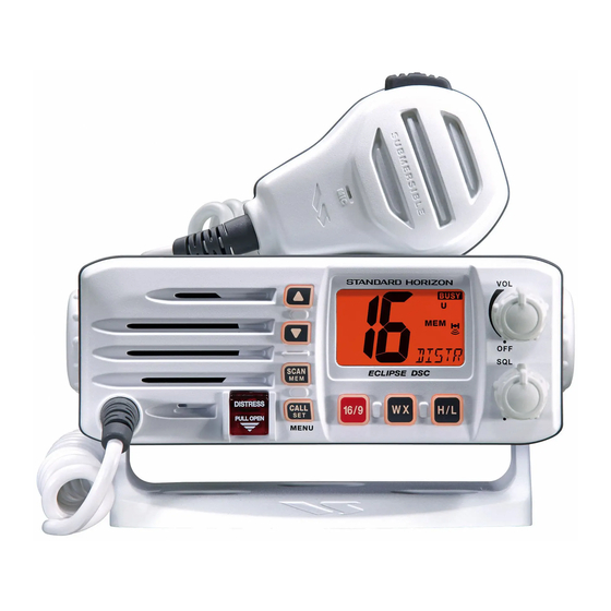
ECLIPSE DSC GX1000S
ECLIPSE DSC GX1000S
ECLIPSE DSC GX1000S
ECLIPSE DSC GX1000S
ECLIPSE DSC GX1000S
This transceiver was assembled using Pb (lead) free solder, based on the RoHS specification.
Only lead-free solder (Alloy Composition: Sn-3.0Ag-0.5Cu) should be used for repairs performed on
this apparatus. The solder stated above utilizes the alloy composition required for compliance with the
lead-free specification, and any solder with the above alloy composition may be used.
25 Watt VHF/FM DSC Marine Transceiver
Important Note
SERVICE MANUAL
EM030N90A
1
Advertisement
Table of Contents

Related Manuals for Standard Horizon Eclipse DSC GX1000S


Summary of Contents for Standard Horizon Eclipse DSC GX1000S
- Page 1 25 Watt VHF/FM DSC Marine Transceiver ECLIPSE DSC GX1000S ECLIPSE DSC GX1000S ECLIPSE DSC GX1000S ECLIPSE DSC GX1000S ECLIPSE DSC GX1000S SERVICE MANUAL Important Note This transceiver was assembled using Pb (lead) free solder, based on the RoHS specification. Only lead-free solder (Alloy Composition: Sn-3.0Ag-0.5Cu) should be used for repairs performed on this apparatus.
-
Page 2: Specifications
Specifications GENERAL Channels: All USA, International and Canadian Input Voltage: 13.8 VDC ±20% Current Drain: Standby 0.3 A Receive 1.0 A Transmit 5.5 A (Hi); 1.5 A (Lo) Individual DSC Directory Memory: Dimensions: 2.4” H x 6.1” W x 6.7” D (60 H x 155 W x 170 D mm) Flush-Mount Dimensions: 2.0”... - Page 3 Exploded View & Miscellaneous Parts CB4557001 MH-76 ASSY (WHITE) CB4557002 RA0976600 MH-76 ASSY (BLACK) RA0995200 (WHITE) RUBBER PACKING (MIC) RA0995300 (BLACK) T9207449 RA0976700 HOOK WIRE ASSY RA0974500 RA0974700 HOLDER (PTT) LOCK PLATE (DC) RUBBER PACKING (DC) T9207450 RA0976400 MIC UNIT WIRE ASSY RUBBER KNOB (PTT) RA0978700...
- Page 4 Exploded View & Miscellaneous Parts Note...
- Page 5 Block Diagram...
- Page 6 Block Diagram Note...
-
Page 7: Circuit Description
Circuit Description Reception and transmission are switched by 8-bit MPU After passing through a limiter amplifier, the signal is IC Q2004 (UPD78F0395GC) on the CNTL Unit. The re- demodulated by the FM detector. Demodulated audio ceiver uses double-conversion superheterodyne circuit- from the FM IF subsystem IC Q1029 (TA31136FNG) is amplified by Q1038 and Q1033 (both 2SC4154). -
Page 8: Dsc Encoder/ Decoder
Circuit Description Transmitter DSC Encoder/ Decoder The voice from the microphone is passed through the Encoder CNTL Unit to the microphone amplifier Q1001 The DSC (Digital Selective Calling) encode signal which (LM2902PW) on the MAIN Unit, a pre-emphasis network, D/A converted in the 8-bit MPU Q2004 (UPD78F0395GC) limiter (IDC: instantaneous deviation control), and low- on the CNTL Unit is fed through the low-pass filter Q1001 pass filter network, the audio is adjusted for optimum de-... -
Page 9: Required Test Equipment
Correct alignment requires that the ambient temperature covered by the warranty policy. Also, Standard Horizon, be the same as that of the transceiver and test equipment, a division of Vertex Standard must reserve the right to and that this temperature be held constant between 68 °F... -
Page 10: Main Reference Frequency Adjustment
Alignment Main Reference Frequency Adjustment Transmit Power Adjustment Setup the test equipment as shown below. Setup the test equipment as shown below. Sampling 50-ohm Inline Coupler GX1000S 50-ohm Dummy Load Wattmeter GX1000S Dummy Load Set the channel to CH16. Use the [ H/L ] key to set the transceiver to “HI” power. Frequency With the PTT switch pressed, adjust VR1001 so that Counter... -
Page 11: Tx Deviation Adjustment
Alignment TX Deviation Adjustment Receiver Front-end Adjustment Setup the test equipment as shown below. Setup the test equipment as shown below. Sampling Tracking Spectrum Coupler GX1000S 50-ohm AF Signal Generator Analizer TP1008 GX1000S Dummy Load Generator Pin 4 J2004 Set the spectrum analyzer as shown below: CENTER: 159.000 MHz Deviation Meter... -
Page 12: Software Alignment/Confirmation Mode
Alignment Software Alignment/Confirmation Mode Overview of Software Alignment Mode Press the [ SCAN ( MEM )] key to re- The “Software Alignment Mode” has been build in the microprocessor in order to adjust and confirm the perfor- call the Alignment Item “SBxxx”. mance of transceiver. - Page 13 MAIN Unit Circuit Diagram RX: 7.8 V RX: 1.1 V RX: 7.8 V RX: 6.0 V RX: 2.9 V RX: 7.4 V RX: 0.2 V RX: 0.4 V RX: 1.2 V 13.8 V TX HI: 4.0 V RX: 5.6 V TX LOW: 0.6 V TX: 8.0 V TX HI: 3.0 V...
- Page 14 MAIN Unit Note...
-
Page 15: Main Unit
MAIN Unit Parts Layout (Side A) S-AV37X NJM2211M (Q1014) (Q1034) TA31136FNG LM2902PWR (Q1029) (Q1001) TB31202FNG (Q1026) LA4425A 2SC4154 (LE) (Q1039) (Q1016, 1023, 1024, 1033, 1035, 1037, 1038) 2SC5006 (24) (Q1017, 1018) 2SK210-GR (YG) 2SK2035 (KP) (Q1019) (Q1031) DTA144EE (16) DTB123EK (F52) (Q1004, 1027) (Q1005, 1009) RT1N441U (N3) - Page 16 MAIN Unit Parts Layout (Side B) NJM7808DL1A LM2904PWR (Q1013) (Q1002) NJM78M05DL1A (Q1012) 3SK131 (V12) 3SK294 (UV) (Q1028) (Q1022) 2SK2035 (KP) 2SC4400 (RT4) (Q1032) (Q1036) 2SC5006 (24) (Q1008) RT1N441U (N3) (Q1007) DAN235U (M) (D1006)
-
Page 17: Parts List
MAIN Unit Parts List DESCRIPTION VALUE TOL. MFR'S DESIG VXSTD P/N VERS. LOT SIDE LAY ADR P.C.B. with Components CS1983701 Printed Circuit Board AM030N000 FR017520C C 1001 CHIP CAP. 0.001uF GRM188B11H102KA01D K22174821 C 1002 CHIP CAP. 0.001uF GRM188B11H102KA01D K22174821 C 1003 CHIP CAP. - Page 18 MAIN Unit Parts List DESCRIPTION VALUE TOL. MFR'S DESIG VXSTD P/N VERS. LOT SIDE LAY ADR C 1079 CHIP CAP. GRM1882C1H7R0DZ01D K22174208 C 1080 CHIP CAP. 0.001uF GRM188B11H102KA01D K22174821 C 1081 CHIP CAP. 0.001uF GRM188B11H102KA01D K22174821 C 1082 CHIP CAP. 0.01uF GRM188B11H103KA01D K22174823...
- Page 19 MAIN Unit Parts List DESCRIPTION VALUE TOL. MFR'S DESIG VXSTD P/N VERS. LOT SIDE LAY ADR C 1175 CHIP TA.CAP. 0.33uF F931V334MAA K78160054 C 1179 CHIP CAP. GRM1883C1H3R0CZ01D K22174204 C 1181 CHIP CAP. 6.3V GRM188B10J105KA01D K22084801 C 1183 CHIP CAP. 6.3V GRM188B10J105KA01D K22084801...
- Page 20 MAIN Unit Parts List DESCRIPTION VALUE TOL. MFR'S DESIG VXSTD P/N VERS. LOT SIDE LAY ADR C 1273 CHIP CAP. 10pF GRM1882C1H100JA01D K22174211 C 1274 CHIP CAP. 0.033uF GRM188R11C333KA01D K22124801 C 1275 CHIP CAP. 0.01uF GRM188B11H103KA01D K22174823 C 1276 CHIP CAP. 0.001uF GRM188B11H102KA01D K22174821...
- Page 21 MAIN Unit Parts List DESCRIPTION VALUE TOL. MFR'S DESIG VXSTD P/N VERS. LOT SIDE LAY ADR Q 1018 TRANSISTOR 2SC5006-T1 G3350068 Q 1019 2SK210-GR(TE85R.F) G3802107G Q 1021 TRANSISTOR RT1N241M-T11-1 G3070249 Q 1022 3SK294(TE85L) G4802948 Q 1023 TRANSISTOR 2SC4154-T11-1E G3341548E Q 1024 TRANSISTOR 2SC4154-T11-1E G3341548E...
- Page 22 MAIN Unit Parts List DESCRIPTION VALUE TOL. MFR'S DESIG VXSTD P/N VERS. LOT SIDE LAY ADR R 1056 CHIP RES. 1/16W RMC1/16 473JATP J24185473 R 1057 CHIP RES. 2.2k 1/16W RMC1/16 222JATP J24185222 R 1058 CHIP RES. 1/16W RMC1/16 473JATP J24185473 R 1059 CHIP RES.
- Page 23 MAIN Unit Parts List DESCRIPTION VALUE TOL. MFR'S DESIG VXSTD P/N VERS. LOT SIDE LAY ADR R 1140 CHIP RES. 2.2k 1/16W RMC1/16 222JATP J24185222 R 1142 CHIP RES. 1/16W RMC1/16 101JATP J24185101 R 1143 CHIP RES. 1/16W RMC1/16 103JATP J24185103 R 1144 CHIP RES.
- Page 24 MAIN Unit Note...
- Page 25 CNTL Unit Circuit Diagram 2.42 V (@13.8 V) CONT "1": 2.7 V CONT "7": 4.7 V 5.0 V DIM "1": 5.7 V DIM "7": 8.5 V DIM "1": 5.4 V DIM "7": 5.9 V 12.0 V DIM "1": 3.5 V DIM "7": 4.9 V 2.5 V TX HI: 4.2 V...
-
Page 26: Cntl Unit
CNTL Unit Parts Layout (Side A) (Side B) UPD78F0395GC BR24L08FVT DTA143ZE (E13) PST597CNR (7C) (Q2004) (Q2006) (Q2001) (Q2003) 2SA1602A (MF) 2SB1132 (BA) 2SC4154 (LE) IMN10 (N10) (Q2015, 2017, 2019) (Q2008) (Q2007) (D2002) ISA1602A (MF) (Q2015, 2017, 2019) - Page 27 CNTL Unit Parts List DESCRIPTION VALUE TOL. MFR'S DESIG VXSTD P/N VERS. LOT SIDE LAY ADR P.C.B. with Components CS1984401 w/VR UNIT Printed Circuit Board AM030N000 FR0175300 C 2007 CHIP CAP. 0.001uF GRM1882C1E102JA01D K22144204 C 2027 CHIP CAP. 0.1uF GRM188F11E104ZA01D K22145001 C 2028 CHIP CAP.
- Page 28 CNTL Unit Parts List DESCRIPTION VALUE TOL. MFR'S DESIG VXSTD P/N VERS. LOT SIDE LAY ADR R 2019 CHIP RES. 1/16W RMC1/16 223JATP J24185223 R 2020 CHIP RES. 1/16W RMC1/16 473JATP J24185473 R 2021 CHIP RES. 100k 1/16W RMC1/16 104JATP J24185104 R 2022 CHIP RES.
-
Page 29: Circuit Diagram
MIC Unit Circuit Diagram Parts Layout (Side A) (Side B) Parts List DESCRIPTION VALUE TOL. MFR'S DESIG VXSTD P/N VERS. LOT SIDE LAY ADR Printed Circuit Board AM030N000 FR017990C C 3502 CERAMIC CAP. 0.001uF BU5 102K6(5MM) K10179056 MC3501 MIC. ELEMENT EM-100PT M3290029 S 3501... - Page 30 VR Unit Parts Layout Parts Layout (Side A) (Side B) Parts List DESCRIPTION VALUE TOL. MFR'S DESIG VXSTD P/N VERS. LOT SIDE LAY ADR Printed Circuit Board AM030N000 FR0176800 J 3001 CONNECTOR 21B12050-07S10B01G3.5/3.5 P0091505 VR3001 POT. WH9011AK-1-34D15/5H=5A20K J60800294 WH9011A-1-40D15/5H=5B20K VR3002 POT. J60800295...
- Page 32 Copyright 2008 VERTEX STANDARD CO., LTD. All rights reserved No portion of this manual may be reproduced without the permission of VERTEX STANDARD CO., LTD.