Table of Contents
Advertisement
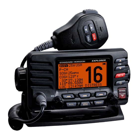
GX1600
25 Watt VHF/FM
Marine Transceiver
Owner's Manual
Ultra slim and compact rear case design (3.5" depth)
Meets ITU-R M493-13 Class D DSC (Digital Selective Calling)
Oversized full dot matrix display
Automatically poll the GPS position of up to 4 ships using DSC
Enter, Save, and Navigate to Waypoints with the Compass page
GPS information(LAT/LON, SOG, and COG) information shown on the LCD
Submersible JIS-8 1.5M (4.92Ft) for 30 minutes
Noise canceling microphone with channel UP/DOWN, 16/9 and H/L keys
NOAA weather channel selection with alert
Programmable Scan, Priority Scan, and Dual Watch
Programmable soft keys
RAM3 Remote Access Microphone capable
Intercom between radio and RAM3 microphone
NMEA 0183 Input and Output
Die-cast chassis
E20 (Easy to Operate)
3 Year Waterproof Warranty
When connected to an optional GPS
GX1600
Page 1
Advertisement
Table of Contents

Related Manuals for Standard Horizon Explorer GX1600


Summary of Contents for Standard Horizon Explorer GX1600
- Page 1 GX1600 25 Watt VHF/FM Marine Transceiver Owner's Manual Ultra slim and compact rear case design (3.5” depth) Meets ITU-R M493-13 Class D DSC (Digital Selective Calling) Oversized full dot matrix display Automatically poll the GPS position of up to 4 ships using DSC Enter, Save, and Navigate to Waypoints with the Compass page GPS information(LAT/LON, SOG, and COG) information shown on the LCD Submersible JIS-8 1.5M (4.92Ft) for 30 minutes...
-
Page 2: Table Of Contents
TABLE OF CONTENTS Quick Reference Guide .................... 4 9 DIGITAL SELECTIVE CALLING ..............34 1 GENERAL INFORMATION ................5 GENERAL ..................34 2 PACKING LIST ....................5 MARITIME MOBILE SERVICE IDENTITY (MMSI) ......34 3 OPTIONS ......................5 9.2.1 What is an MMSI? .............. 34 4 ON-LINE WARRANTY REGISTRATION ( in USA or Canada only ) .... - Page 3 TABLE OF CONTENTS 10 GENERAL SETUP ................... 68 13 WAYPOINTS ...................... 84 10.1 DISPLAY .................... 68 13.1 MARKING A POSITION ..............84 10.2 DIMMER ADJUSTING ............... 69 13.2 ADDING A WAYPOINT ..............85 10.3 CONTRAST ..................69 13.3 EDITING A WAYPOINT ..............86 10.4 TIME OFFSET ..................
-
Page 4: Quick Reference Guide
This transceiver is equipped with the E2O (Easy-To-Operate) system. You can do the basic operation in numerical order of the illustration below. Press and hold the button to turn on or off the radio. Rotate the VOL knob to adjust the speaker audio volume. Press the (or microphones ) button to selects the... -
Page 5: General Information
1 GENERAL INFORMATION The STANDARD HORIZON EXPLOPER GX1600 Marine VHF/FM Marine transceiver is capable of ITU-R 493-13 DSC (Digital Selective Calling) Class D operation. Class D operation allows continuous receiving of Digital Selective Calling functions on channel 70 even if the radio is receiving a call. The GX1600 VHF operate on all currently-allocated marine channels which are switchable for use with USA, International, or Canadian regulations. -
Page 6: On-Line Warranty Registration In Usa Or Canada Only
4 ON-LINE WARRANTY REGISTRATION in USA or Canada only Please visit www.standardhorizon.com to register the GX1600 Marine VHF. It should be noted that visiting the Web site from time to time may be beneficial to you, as new products are released they will appear on the STANDARD HORIZON Web site. -
Page 7: Getting Started
5 GETTING STARTED PROHIBITED COMMUNICATIONS The FCC prohibits the following communications: • False distress or emergency messages: • Messages to “any boat” except in emergencies and radio tests; • Messages to or from a vessel on land; • Transmission while on land; •... -
Page 8: Coaxial Cable
COAXIAL CABLE VHF antennas are connected to the transceiver by means of a coaxial cable – a shielded transmission line. Coaxial cable is specified by it’s diameter and construction. For runs less than 20 feet, RG-58/U, about 1/4 inch in diameter is a good choice. -
Page 9: Calling Another Vessel (Channel 16 Or 9)
7. Estimate the present seaworthiness and condition of your vessel. 8. Give your vessel’s description: length, design (power or sail), color and other distinguishing marks. The total transmission should not exceed 1 minute. 9. End the message by saying “OVER”. Release the microphone button and listen. -
Page 10: Making Telephone Calls
After a transmission, say “over,” and release the microphone’s push-to-talk (PTT) switch. When all communication with the other vessel is completed, end the last transmission by stating your Call Sign and the word “out.” Note that it is not necessary to state your Call Sign with each transmission, only at the beginning and end of the contact. - Page 11 The Automated Radio Check Service is currently available in the areas listed below. West Coast Sea Tow Newport/LA - Ch. 27 Sea Tow San Diego - Ch. 27 Northeast Sea Tow Portland-Midcoast (Maine) - Ch. 27 Sea Tow Boston - Ch. 27 Sea Tow South Shore (Mass.) - Ch.
-
Page 12: Installation
6 INSTALLATION SAFETY / WARNING INFORMATION This radio is restricted to occupational use, work related operations only where the radio operator must have the knowledge to control the exposure condi- tions of its passengers and bystanders by maintaining the minimum separa- tion distance of 0.89 m (2.92 feet). -
Page 13: Mounting The Radio
MOUNTING THE RADIO 6.3.1 Supplied Mounting Bracket The supplied mounting bracket allows overhead or desktop mounting. Use a 13/64” (5.2 mm) bit to drill the holes to a surface which is more 0.4 inch (10 mm) thick and can support more than 3.3 lbs (1.5 kg) and secure the bracket with the supplied screws, spring... -
Page 14: Electrical Connections
ELECTRICAL CONNECTIONS CAUTION Reverse polarity battery connections will damage the radio! Connect the power cord and antenna to the radio. Antenna and Power Supply connections are as follows: 1. Mount the antenna at least 3 feet (1 m) away from the radio. At the rear of the radio, connect the antenna cable. -
Page 15: Accessory Cable
ACCESSORY CABLE White External Speaker Shield GPS Receiver Radio Wires Plotter Connection Blue: NMEA GPS Input ( ) NMEA OUT ( ) Green: NMEA GPS Input ( ) NMEA OUT ( ) Gray: NMEA DSC Output ( ) NMEA IN ( ) Brown: NMEA DSC Output ( ) NMEA IN ( ) Wire Color/Description... -
Page 16: Checking Gps Connections
CHECKING GPS CONNECTIONS After connections have been made between the GX1600 and the GPS, a small satellite icon will appear on the top right corner of the display and your current location (Latitude/Longitude) is shown on the display. NOTE If there is a problem with the NMEA connection between the radio and the GPS, the GPS icon will blink continuously until the connection is corrected. -
Page 17: Changing The Time Area
CHANGING THE TIME AREA This menu selection allows the radio to show UTC time or local time with the offset. 1. Press and hold down the key until “Setup Menu” appears, then select “GENERAL SETUP” with the key. 2. Press the soft key, then press the key to “TIME AREA”. -
Page 18: Changing Cog To True Or Magnetic
6.10 CHANGING COG TO TRUE OR MAGNETIC Allows the GPS Course Over Ground to be selected to show in True or Mag- netic. Factory default is True however by following the steps below the COG can be changed to Magnetic. 1. - Page 19 5. Referring to illustration below, make a 1.2” (30 mm) hole in the wall, then insert the Extension Cable into this hole. Connect the Gasket and Mount Base to the Extension Cable Connector using the Nut. 6. Drill the four Screw holes (approx. 2 mm) on the wall, then install the Mount- ing Base to the wall using four screws.
-
Page 20: Connecting An External Speaker To The Ram3 Mic Cable
6.11.1 Connecting an External Speaker to the RAM3 Mic Cable In noisy locations and optional external speaker may be connected to the white speaker wires on the RAM3 routing cable. The RAM3 can drive the internal speaker or the external speaker one at a time. When connecting an external speaker, follow the procedure below to turn off the RAM3 audio and enable the external speaker wires on the RAM3 routing cable. - Page 21 MEMO GX1600 Page 21...
-
Page 22: Controls And Indicators
7 CONTROLS AND INDICATORS NOTE This section defines each control of the transceiver. For operating in- structions refer to section “8 BASIC OPERATION”. FRONT PANEL keys are used to select channels and to choose menu items (such as the DSC menu, Radio Setup and DSC Setup menu). keys on the microphone can also be used to select channels and menu items. - Page 23 [ DISTRESS ] Key Used to send a DSC Distress Alert. To transmit a Distress Alert refer to section “9.3.1 Transmitting a DSC Distress Alert”. VOL Knob ( Volume Control Knob ) Adjusts the audio volume level. Turn this knob clockwise to increase the audio volume level.
-
Page 24: Rear Panel
REAR PANEL RAM3 Connector ( Remote Station Microphone Connector ) Connects the GX1600 to the RAM3 ( CMP30 ) Remote Station Microphone. Refer to section “14 RAM3 ( CMP30 ) REMOTE MIC OPERATION” for de- tails DC Input Cable Connects the radio to a DC power supply capable of delivering 11 to 16V External Speaker Connection Cable ( White &... -
Page 25: Microphone
MICROPHONE PTT ( Push-To-Talk ) Switch When in radio mode and the PTT switch pressed, the transmitter is enabled for voice communications to another vessel. When a optional RAM3 second sta- tion microphone is connected and intercom mode is selected, press- ing the PTT switch enables voice communications from the GX1600 to the RAM3 second station micro-... -
Page 26: Basic Operation
8 BASIC OPERATION RECEPTION 1. After the transceiver has been installed, ensure that the power supply and antenna are properly connected. 2. Press and hold the key until the radio turns on. 3. Rotate the SQL knob fully counterclockwise until “ ”... -
Page 27: Simplex/Duplex Channel Use
SIMPLEX/DUPLEX CHANNEL USE Refer to section “16 CHANNEL ASSIGNMENTS” for instructions on use of simplex and duplex channels. NOTE All channels are factory-programmed in accordance with FCC (USA), Industry Canada (Canada), and International regulations. Mode of op- eration cannot be altered from simplex to duplex or vice-versa. DISPLAY TYPE The GX1600 display can be setup to show displays other than the default “NORMAL”... -
Page 28: Usa, Canada, And International Mode
USA, CANADA, AND INTERNATIONAL MODE To change the channel group from USA to Canada or International: 1. Press and hold down the key until “Setup Menu” appears. 2. Press the key to select “CH FUNC- TION SETUP”. 2. Press the soft key, then press the key to select “CH GROUP”. -
Page 29: Noaa Weather Testing
NOTE If a key is not pressed the alert will sound for 5 minutes and then the weather report will be received. NOTE While listening to a weather channel, the radio can decode a weather alert and sound an alarm. 8.7.2 NOAA Weather Alert Testing NOAA tests the alert system ever Wednesday between 11AM and 1PM. -
Page 30: Scanning
SCANNING Allows the user to select the scan type from Memory scan or Priority scan. “Memory scan” scans the channels that were programmed into memory. “Pri- ority scan” scans the channels programmed in memory with the priority chan- nel. 8.9.1 Scan Type Selection 1. -
Page 31: Memory Scanning M-Scan
8.9.3 Memory Scanning M-SCAN 1. Adjust the SQL knob until background noise disappears. 2. Press the one of the Soft keys momentarily, then press the soft key. “M-SCAN” appears on the display. Scanning will proceed from the lowest to the highest programmed channel number and Preset channel (described in the next chapter) and will stop on a channel when a transmission is received. -
Page 32: Preset Channels 0 ~ 9 : Instant Access
8.10 PRESET CHANNELS 0 ~ 9 : INSTANT ACCESS 10 Preset Channels can be programmed for instant access. Pressing the key activates the preset channel bank. If the key is pressed and no chan- nels have been assigned, an alert beep will be emitted from the speaker. 8.10.1 Preset Channel Programming 1. -
Page 33: Intercom Operation
8.11 INTERCOM OPERATION An optional RAM3 ( CMP30 ) must be connected to perform intercom functions between the radio and the RAM3 ( CMP30 ) . In addition, To access the following Intercom functions one of the soft keys must be setup as . -
Page 34: Digital Selective Calling
9 DIGITAL SELECTIVE CALLING GENERAL WARNING This radio is designed to generate a digital maritime distress and safety call to facilitate search and rescue. To be effective as a safety device, this equipment must be used only within communication range of a shore- based VHF marine channel 70 distress and safety watch system. -
Page 35: Programming The Mmsi
How can I obtain an MMSI assignment? In the USA, visit the following websites to register: http://www.boatus.com/mmsi/ or http://seatow.com/boating_safety/mmsi.asp In the Canada, visit http://www.ic.gc.ca/epic/site/smt-gst.nsf/en/sf01032e.html or http://www.usps.org/php/mmsi/rules.php 9.2.2 Programming the MMSI WARNING A user MMSI can be inputted only once. Therefore please be careful not to input the incorrect MMSI number. -
Page 36: Dsc Distress Alert
DSC DISTRESS ALERT The GX1600 is capable of transmitting and receiving DSC Distress messages with your vessels position when connected to a GPS with NMEA 0183 output. Refer to section “6.5 ACCESSORY CABLE”. 9.3.1 Transmitting a DSC Distress Alert NOTE To be able to transmit a DSC Distress Alert an MMSI number must be programmed, refer to section “9.2.2 Programming the MMSI.”... -
Page 37: Transmitting A Dsc Distress Alert With Nature Of Distress
9.3.1.1 Transmitting a DSC Distress Alert with Nature of Distress The GX1600 is capable of transmitting a DSC Distress Alert with the following “Nature of Distress” categories you may have: Undesignated, Fire, Flooding, Collision, Grounding, Capsizing, Sinking, Adrift, Abandoning, Piracy, MOB 1. -
Page 38: Transmitting A Dsc Distress Alert By Manually Entering A Position
9.3.1.2 Transmitting a DSC Distress Alert by Manually Entering a Position When the GX1600 is not connected to a GPS receiver or the GPS has a prob- lem, you may input the latitude/longitude of your vessel manually and may send DSC Distress Alert. -
Page 39: Pausing A Dsc Distress Call
9.3.1.3 Pausing a DSC Distress Call After a DSC Distress call is transmitted, the DSC distress call is repeated every 4 minutes until the call is canceled by the user or until the radio is turned on and off again. The GX1600 has provision to suspend (Pause) the retrans- mitting of the distress call by the procedure below. - Page 40 cursor by pressing the soft key). 6. The ID is the MMSI from the vessel in distress. 7. When you are finished entering the waypoint name, press and hold the soft key to replace the display to the “WAYPOINT” Screen. The display in- dicates the distance and direction of the vessel in distress by a dot ( ) .
-
Page 41: All Ships Call
ALL SHIPS CALL The All Ships Call function allows contact to be established with DSC equipped vessels without having their MMSI in the individual calling directory. Also, pri- ority for the call can be designated as Urgency or Safety. URGENCY Call: This type of call is used when a vessel may not truly be in distress, but have a potential problem that may lead to a dis- tress situation. -
Page 42: Receiving An All Ships Call
9.4.2 Receiving an All Ships Call 1. When an all ships call is received, an emergency alarm will sound. The display shows the MMSI of the vessel transmit- ting the All Ships Call and the radio will change to the requested channel after 10 seconds. 2. -
Page 43: Individual Call
INDIVIDUAL CALL This feature allows the GX1600 to contact another vessel with a DSC VHF radio and automatically switch the receiving radio to a desired communica- tions channel. This feature is similar to calling a vessel on CH16 and request- ing to go to another channel (switching to the channel is private between the two stations). -
Page 44: Individual Reply Setup
10. Press the key to scroll through numbers, 0-9. To enter the desired number and move one space to the right by pressing the soft key. Repeat this procedure until all nine space of the MMSI number are entered. 11. If a mistake was made entering in the MMSI number repeat pressing the soft key until the wrong number is selected, then press the key to correct the entry. -
Page 45: Individual/Group Call Ringer Setup
1. Press and hold down the key until “Setup Menu” appears. 2. Press the key to select “DSC SETUP” menu. 3. Press the soft key, then select “INDI- VIDUAL ACK” with the key. 4. Press the soft key. 5. Press the key to select “ABLE TO COMPLY”... -
Page 46: Transmitting An Individual Call
or “Group” if you wish to disable the Group call ringer, then press the soft key. 6. Press the key to select “Off”. 7. Press the soft key to store the selected set- ting, then press the soft key several times to return to radio opera- tion. -
Page 47: Individual Call By Manually Entering A Mmsi
9.5.5.2 Individual Call by Manually Entering a MMSI You may enter an MMSI number manually to contact another vessel. 1. Press the key. The “DSC Menu” menu will ap- pear. 2. Press the key to select “INDIVIDUAL”. (To cancel, press the soft key.) 3. -
Page 48: Receiving An Individual Call
make sure it is not busy, then press the microphone’s PTT switch and talk into the microphone to the other vessel. 9.5.6 Receiving an Individual Call When a Individual DSC call is received, the radio will automatically respond (Default setting) to the calling ship, and switch to the requested channel for voice communications. -
Page 49: Dsc Log Operation
DSC LOG OPERATION The GX1600 logs received distress calls and othet calls (Individual, Group, All Ship etc.). The DSC Log feature is similar to an answer machine where calls are recorded for review and a “ ” icon will appear on the radios display. The GX1600 can store up to the latest 27 Distress, and up to the latest 64 other calls. -
Page 50: Deleting A Call From The "Dsc Log" Directory
5. Press the soft key, to review details for the selected station. 9.6.3 Deleting a Call from the “DSC LOG” Directory 1. Press the key. The “DSC Menu” will ap- pear. 2. Press the key to select “DSC LOG” menu. 3. -
Page 51: Group Call
MMSI numbers. The first digit of a Group MMSI is always set to “0” by International rules. All Standard Horizon radios are preset so when programming a Group MMSI the first digit is set to “0”. -
Page 52: Transmitting A Group Call
5. Press the soft key. 6. Press the key to scroll through the first letter of the name of the group you want to refer- ence in the directory. 7. Press the soft key to store the first letter in the name and step to the next letter to the right. -
Page 53: Group Call By Manually Entering A Mmsi
] soft key. municate on, then press the If the channel you want is not shown, press soft key, then press the key to select the operating channel you want to communicate on, then press the soft key. 6. Press the soft key to transmit the Group Call signal. -
Page 54: Receiving A Group Call
9. When finished entering the MMSI number, press and hold the soft key. 10. Press the key to select the oper- ating channel you want to communicate on, then press the soft key. If the channel you want is not shown, press the soft key, then press the key to select... -
Page 55: Position Request
GX1600. Standard Horizon has taken this feature one step further, if any compatible GPS chart plotter is connected to the GX1600, the polled position of the vessel is shown on the display of the GPS chart plotter making it easy to navigate to the location of the polled vessel. -
Page 56: Position Request Ringer Setup
9.8.2 Position Request Ringer Setup The GX1600 has the capability to turn off the Position Request ringer. 1. Press and hold down the key until “Setup Menu” appears. 2. Press the key to select “DSC SETUP” menu. 3. Press the soft key, then select “DSC BEEP”... -
Page 57: Position Request By Manually Entering A Mmsi
9.8.3.2 Position Request by Manually Entering a MMSI This feature allows you to request the position of vessel by manually entering the MMSI of the ship you want to send your position to. 1. Press the key. The “DSC Menu” will ap- pear. - Page 58 Manually reply: 1. When a position request call is received from an- other vessel, the display will be as shown in the il- lustration at the right. 2. A ringing alarm sounds 4 times. To send your ves- sels position to the requesting vessel, press the soft key.
-
Page 59: Position Report
POSITION REPORT The feature is similar to Position Request, however instead of requesting a position of another vessel this function allows you to send your position to another vessel. Your vessel must have an operating GPS receiver connected for the GX1600 to send the position. NOTE To transmit a Position Report Call, a GPS must be connected to the radio and the GX1600 Individual directory must be programmed with... -
Page 60: Dsc Position Report Call By Manually Entering A Mmsi
6. Press the key to return to radio operation. 9.9.2.2 DSC Position Report Call by Manually Entering a MMSI This feature allows you to send your position to another vessel by manually entering the MMSI of the ship you want to send your position to. 1. -
Page 61: Receiving A Dsc Position Report Call
9.9.3 Receiving a DSC Position Report Call When another vessel transmits their vessels location to the GX1600 the fol- lowing will happen: 1. A ringing sound will be produced when the call is received and NMEA sentences DSC, DSE are outputted so the position can be shown on a chart plotter or a computer. -
Page 62: Saving A Position Report Call As A Waypoint
9.9.6 Saving a Position Report Call as a Waypoint The GX1600 can save a Position Report call in the radios memory as a waypoint. 1. After the Position Report call has been received: Press the soft key. 2. Press the key to change the first letter in the name of the waypoint and press the soft... -
Page 63: Manual Inputting A Gps Position Lat/Lon
9.10 MANUAL INPUTTING A GPS POSITION LAT/LON This selection allows the Latitude/Longitude of your vessel to be manually entered so DSC Distress or a Position Report call will contain position informa- tion. This feature maybe useful when a connected GPS fails to supply position to the radio. -
Page 64: Auto Dsc Polling
9.11 AUTO DSC POLLING The GX1600 has the capability to automatically track four stations programmed into the Indvidual directory. 9.11.1 Polling Time Interval Setup The following steps allows the radio to setup the interval time between DSC Position Request Transmissions. 1. -
Page 65: Enable/Disable Auto Dsc Polling
6. Repeat steps 4 and 5 for CALL 2, CALL 3 and CALL 4 entries. 7. When finished, press the soft key numer- ous times to exit to the radio mode. 9.11.3 Enable/Disable Auto DSC Polling 1. Press the key. The “DSC Menu” will ap- pear. -
Page 66: Dsc Test
9.12 DSC TEST This function is used to contact another DSC equipped vessel to ensure the DSC functions of the radio are operating. NOTE To use this feature, the radio you will be transmitting the test call to needs to have the DSC Test feature. To perform the DSC test you will need to enter a MMSI of another vessel into the Individual directory or manually enter in the MMSI using the procedure below. -
Page 67: Dsc Test Call By Manually Entering Mmsi
9.12.3 DSC Test Call by Manually Entering a MMSI 1. Press the key. The “DSC Menu” will ap- pear. 2. Press the key to select “DSC TEST”, then press the soft key. 3. Press the key to select “MANUAL” and press the soft key. -
Page 68: General Setup
10 GENERAL SETUP The optional RAM3 ( CMP30 ) Remote Station Microphone can also ad- just items in the setup menu using the following procedures. 10.1 DISPLAY The GX1600 can select additional screens other than the default “NORMAL” (Radio) Display by using the procedure below. “NORMAL”... -
Page 69: Dimmer Adjusting
10.2 DIMMER ADJUSTING This menu selection adjusts the backlight intensity of the display and keypad. 1. Press and hold down the key until “Setup Menu” appears, then select “GENERAL SETUP” with the key. 2. Press the soft key, then press the key to select “DIMMER”. -
Page 70: Time Offset
10.4 TIME OFFSET Sets the time offset between local time (with inputted offset) and UTC (without time offset) shown on the display. Time is displayed only when an optional GPS Chart Plotter is connected. 1. Press and hold down the key until “Setup Menu”... -
Page 71: Time Area
10.5 TIME AREA This menu selection allows the radio to show UTC time or local time with the offset. 1. Press and hold down the key until “Setup Menu” appears, then select “GENERAL SETUP” with the key. 2. Press the soft key, then press the key to “TIME AREA”. -
Page 72: Unit Of Measure
10.7 UNIT OF MEASURE Allows Navigation and AIS displays to be shown in “Knot”, “Mile/Hour” or “Kilo- Meter/Hour” (for speed) and “Nautical Mile” or “Kilo-Meter” (for distance). NOTE A GPS must be connected to the radio to be able to show SPEED and DISTANCE. -
Page 73: Magnetic
10.8 MAGNETIC This selection allows customizing the GPS COG (Course Over Ground) dis- played in True or Magnetic. NOTE A GPS must be connected to the radio to be able to show COG. 1. Press and hold down the key until “Setup Menu” appears, then select “GENERAL SETUP”... -
Page 74: Station Name
10.10 STATION NAME This function allows you to change the name of the radio or RAM3 second station microphone. Example: “Radio - Cabin”, “RAM1 - Flybridge”. 1. Connect the RAM3 second station microphone to the GX1600. 2. Press and hold down the key until “Setup Menu”... -
Page 75: Soft Keys
10.11 SOFT KEYS This menu item assigns the number of soft keys, soft key selection and how long the display will show the soft key icon after a soft key is pressed. 10.11.1 Selecting the Number of Soft Keys 1. Press and hold down the key until “Setup Menu”... -
Page 76: 1011.3 Selecting How Long The Soft Keys Are Shown
5. Repeat step 4 to program the other soft keys. The factory defaults are Key , Key 2: , and Key 3: function. 6. Press the soft key to store the selected setting. 7. Press the soft key several times to return to radio operation. 10.11.3 Selecting How Long the Soft Keys are Shown 1. -
Page 77: Channel Function Setup
11 CHANNEL FUNCTION SETUP 11.1 CHANNEL GROUP USA, CANADA or INTERNATIONAL BAND SELECTION This section selects a channel group from USA, Canada, and International. 1. Press and hold down the key until “Setup Menu” appears. 2. Press the key to select “CH FUNC- TION SETUP”. -
Page 78: Scan Type
11.3 SCAN TYPE This selection is used to select the scan mode between “Memory Scan” and “Priority Scan”. The default setting is Priority Scan. 1. Press and hold down the key until “Setup Menu” appears. 2. Press the key to select “CH FUNCTION SETUP”. -
Page 79: Priority Channel
11.5 PRIORITY CHANNEL By default the radio priority channel is set to channel 16. This procedure allows the radio to use a different priority channel used when priority scanning. 1. Press and hold down the key until “Setup Menu” appears. 2. -
Page 80: Channel Name
11.7 CHANNEL NAME When radio mode (NORMAL) is selected, the display will show a name under the channel number. This name describes the use of the channel. The radio has the capability to customize the name by the procedure below. Example: CH69 PLEASURE to HOOKUP 1. -
Page 81: Dsc Setup
12 DSC SETUP 12.1 INDIVIDUAL DIRECTORY The GX1600 has a DSC directory that allows you to store a vessel or person’s name and the MMSI number associated with vessels you wish to transmit Individual calls, Position Requests and Position Send transmissions. To transmit an Individual call you must program this directory with information of the persons you wish to call, similar to a cellular phones telephone directory. -
Page 82: Position Reply
12.6 POSITION REPLY The GX1600 can be set up to automatically (default setting) or manually send your position when requested by another vessel. This selection is important if you are concerned about someone polling the position of your vessel that you may not want to. -
Page 83: Auto Channel Switch Time
12.8 AUTO CHANNEL SWITCH TIME When a DSC Distress or ALL Ships (Urgency or Safety) call is received, the GX1600 will automatically switch to channel 16. This menu selection allows the automatic switch time to be changed. The de- fault selection is 30 seconds. 1. -
Page 84: Waypoints
13 WAYPOINTS The GX1600 is capable of storing up to 100 waypoints and navigating to them using the compass page. In addition DSC distress calls with position or a position received from a an- other DSC radio using DSC polling can be navigated to. 13.1 MARKING A POSITION This feature allows the radio to mark the current position of the vessel. -
Page 85: Adding A Waypoint
13.2 ADDING A WAYPOINT 1. Press and hold down the key until “Setup Menu” appears. 2. Press the key to select “WAYPOINT SETUP”. 3. Press the soft key, then select “WAYPOINT DIRECTORY” with the key. 4. Press the soft key, then select “ADD” with the key. -
Page 86: Editing A Waypoint
13.3 EDITING A WAYPOINT This function allows a previously entered waypoint to be edited. 1. Press and hold down the key until “Setup Menu” appears. 2. Press the key to select “WAYPOINT SETUP”. 3. Press the soft key, then select “WAYPOINT DIRECTORY”... -
Page 87: Saving A Dsc Position Call As A Waypoint
13.5 SAVING A DSC POSITION CALL AS A WAYPOINT When a DSC POSITION REPORT call is received from a another DSC radio the GX1600 allows the position to be saved as a waypoint. 1. After a position has been received, press the soft key. -
Page 88: Stop Navigating To A Waypoint
13.7 STOP NAVIGATING TO A WAYPOINT To stop navigating to a waypoint, press the one of the Soft keys, then press the soft key. The radio is switched to Normal Mode. Press the soft key to open the “Waypoint Direc- tory”... - Page 89 MEMO GX1600 Page 89...
-
Page 90: Ram3 Cmp30 Remote Mic Operation
14 RAM3 CMP30 REMOTE MIC OPERATION When an optional RAM3 Remote mic is connected to the GX1600, all VHF, DSC, setup menus, AIS, Waypoint, Compass functions and PA/Fog modes can be remotely operated. The RAM3’s operation is same as GX1600 except the receiver audio volume setting and squelch level setting. - Page 91 PTT (Push-To-Talk) Key Push this key to enable the transmitter. ( POWER ) Key Press and hold down this key to turn the transceiver and Remote MIC on or off. MICROPHONE The internal ClearVoice Noise Canceling mic is located here. When transmitting, position your mouth about 1/2 to 1 inch (1.2 ~ 2.5 cm) away from the small mic hole.
-
Page 92: Assigning Soft Keys
Press to CLEAR a function or menu selection. Press and hold to select NOAA Weather channels. Press and hold again to exit Weather mode and revert to radio mode. Secondary use Hold down the key while pressing the key to change the mode from USA to International or Canadian. -
Page 93: Soft Key
gram the other soft keys. 7. Press the soft key, then press the key to select “KEY TIMER” (selects how long the soft key icon will be shown on the display after a soft key is pressed, default is 5 seconds). Then, press the soft key. -
Page 94: Maintenance
Ensure that the supply voltage to the transceiver does not exceed 16 VDC or fall below 11 VDC. • Use only STANDARD HORIZON-approved accessories and replacement parts. In the unlikely event of serious problems, please contact your Dealer or our repair facility. -
Page 95: Troubleshooting Chart
An “RA” Return Authorization number is not necessary to send a product in for service. Include a brief note describing the problem along with your name, return address, phone number, and proof of purchase. 15.3 TROUBLESHOOTING CHART SYMPTOM PROBABLE CAUSE REMEDY Transceiver fails to No DC voltage to the... -
Page 96: Channel Assignments
16 CHANNEL ASSIGNMENTS Tables on the following columns list the VHF Marine Channel assignments for U.S.A. and International use. Below are listed some data about the charts. 1. VTS. Where indicated, these channels are part of the U.S. Coast Guard’s Vessel Traffic System. - Page 97 6. Marine vessels equipped with VHF radios are required to monitor Channel 7. 156.050 MHz and 156.175 MHz are available for port operations and com- mercial communications purposes when used only within the U.S. Coast Guard designated Vessel Traffic Services (VTS) area of New Orleans, on the lower Mississippi River from the various pass entrances in the Gulf of Mexico to Devil’s Swamp Light at River Mile 242.4 above head of passes near Baton Rouge.
- Page 98 12. Use of 156.375 MHz is available for navigational communications only in the Mississippi River from South Pass Lighted Whistle Buoy “2” and South- west Pass entrance Mid channel Lighted Whistle Buoy to mile 242.4 above head of Passes near Baton Rouge, and in addition over the full length of the Mississippi River-Gulf Outlet Canal from entrance to its junction with the Inner Harbor Navigation Canal, and over the full length of the Inner Harbor Navigation Canal from its junction with the Mississippi River to its...
- Page 99 VHF MARINE CHANNEL CHART CHANNEL USE D 156.050 160.650 Public Correspondence (Marine Operator) 156.050 Port Operation and Commercial. VTS in selected areas D 156.100 160.700 Public Correspondence (Marine Operator) D 156.150 160.750 Public Correspondence (Marine Operator) 156.150 U.S. Government Only, Coast Guard D 156.200 160.800 Public Correspondence (Marine Operator), Port operation, ship movement 156.200...
- Page 100 VHF MARINE CHANNEL CHART CHANNEL USE D 156.025 160.625 Public Correspondence (Marine Operator) D 156.075 160.675 Public Correspondence (Marine Operator), Port operation, ship movement 156.075 Public Coast: Coast Guard; East Coast: commercial fishing only D 156.125 160.725 Public Correspondence (Marine Operator), Port operation, ship movement 156.125 Public Coast: Coast Guard;...
- Page 101 VHF MARINE CHANNEL CHART CHANNEL USE D 157.025 161.625 Port operation, ship movement 157.025 Commercial D 157.075 161.675 Port operation, ship movement 157.075 U.S. Government Only - Environmental protection operations. 157.075 Canadian Coast Guard Only D 157.125 161.725 Public Correspondence (Marine Operator), Port operation, ship movement 157.125 U.S.
-
Page 102: Warranty
Speakers, Antennas, Carrying Accessories, Power Supplies, and Signaling Boards. To receive warranty service, the purchaser must deliver the Product, transpor- tation and insurance prepaid, to STANDARD HORIZON (a division of VER- TEX STANDARD), Attention Marine repairs 10900 Walker Street, Cypress, CA 90630. - Page 103 Products on which the serial number has been removed, defaced, or changed. STANDARD HORIZON cannot be responsible in any way for ancillary equip- ment not furnished by STANDARD HORIZON which is attached to or used in connection with STANDARD HORIZON’s Products, or for the operation of the Product with any ancillary equipment, and all such equipment is expressly excluded from this warranty.
- Page 104 Product Support Inquiries If you have any questions or comments regarding the use of the radio, you can visit the STANDARD HORIZON Web site to send an E-Mail or contact the Product Support team at (714) 827-7600 ext 6300 M-F 7:00- 5:00PST.
-
Page 105: Reset Procedures
18 RESET PROCEDURES 18.1 MEMORY CLEAR To clear the Scan memory and Preset memory: 1. Turn the radio off. 2. Press and hold in the three [ Programmable ] keys while turning the radio 18.2 MICROPROCESSOR RESETTING To clear all memories and other settings to factory defaults (except the Chan- nel Group, MMSI number, and DSC directory information): 1. -
Page 106: Specifications
19 SPECIFICATIONS Performance specifications are nominal, unless otherwise indicated, and are subject to change without notice. 19.1 GENERAL Channels ..........All USA, International and Canadian Normal Input Voltage ..............13.8 V DC Operating Voltage Range ............11 V to 16.5 V Current Drain Standby ................... -
Page 107: Receiver
19.3 RECEIVER Frequency Range ..........156.050 MHz to 163.275 MHz Sensitivity 20 dB Quieting ................0.35 µV 12 dB SINAD ................. 0.25 µV Squelch Sensitivity (Threshold) ............. 0.13 µV Modulation Acceptance Bandwidth ...........±7.5 kHz Selectivity (Typical) Spurious and Image Rejection ....80 dB for Voice (75 dB for DSC) Intermodulation and Rejection .... -
Page 108: Dimensions
19.5 DIMENSIONS Page 108 GX1600... - Page 109 GX1600 Page 109...
-
Page 110: Fcc Radio License Information
20 FCC RADIO LICENSE INFORMATION Standard Horizon radios comply with the Federal Communication Commis- sion (FCC) requirements that regulate the Maritime Radio Service. 20.1 STATION LICENSE An FCC ship station license is no longer required for any vessel traveling in U.S. -
Page 111: Fcc Notice
Unauthorized changes or modifications to this equipment may void com- pliance with FCC Rules. Any change or modification must be approved in writing by STANDARD HORIZON. NOTICE This equipment has been tested and found to comply with the limits for a Class B digital device, pursuant to Part 15 of the FCC Rules. - Page 112 Copyright 2010 VERTEX STANDARD CO., LTD. Marine Division of VERTEX STANDARD All rights reserved. US Headquarters No portion of this manual 10900 Walker Street, Cypress, CA 90630, U.S.A. may be reproduced www.standardhorizon.com without the permission of VERTEX STANDARD CO., LTD. Printed in China Page 112 GX1600...