Table of Contents
Advertisement
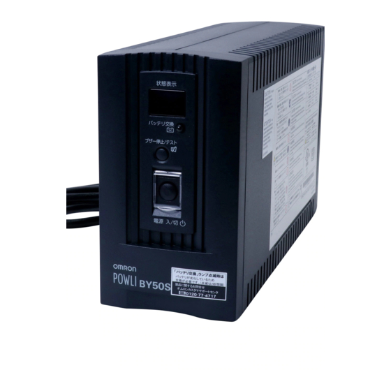
Uninterruptible Power Supply
Instruction Manual
• This manual provides important safety-related information. Thoroughly read and understand
this manual before installing and using the product.
• Keep this manual in a convenient location so that you can refer to it whenever necessary.
• The contents of this manual are subject to change without notice.
BY35S/BY50S
BY80S/BY120S
Advertisement
Table of Contents

Related Manuals for Omron Powli BY35S


Summary of Contents for Omron Powli BY35S
- Page 1 Uninterruptible Power Supply BY35S/BY50S BY80S/BY120S Instruction Manual • This manual provides important safety-related information. Thoroughly read and understand this manual before installing and using the product. • Keep this manual in a convenient location so that you can refer to it whenever necessary. •...
-
Page 2: Introduction
● The names of other companies and products mentioned herein are the trademarks or registered trademarks of their respective owners. ● Note on user registration Please fi ll out the required items on the included user registration card and send it to our customer support center. ©OMRON Corporation. 2011 All Rights Reserved. -
Page 3: Important Safety Instruction
IMPORTANT SAFETY INSTRUCTION 1. SAVE THESE INSTRUCTIONS. This manual contains important instructions for BY35S/BY50S/BY80S/ BY120S that should be followed when using the UPS and batteries. 2. SYMBOL Power output ON/OFF switch. 3. INTERNAL BATTERY Internal battery voltage is 12V DC FOR BY35S/BY50S/BY80S/ BY120S. -
Page 4: Preparation For Operation
Procedure from installation to operation Read “Safety precautions” Start Page v Take out the product from the package and check the contents Page 1 Installation/connection Perform installation and connection Page 6 Are you Read “Using the UPS using UPS monitoring monitoring software”. -
Page 5: Table Of Contents
Table of Contents Table of Contents Introduction ............................i IMPORTANT SAFETY INSTRUCTION ....................ii Safety precautions ..........................v 1. Preparation .............................1 Unpacking the product ......................... 1 Checking the contents ......................... 1 Name of each part ..........................2 Explanation of symbols used on unit ....................5 2. -
Page 6: Safety Precautions
S / BY S BY S / BY Important information for safe operation is described. Safety precautions Be sure to read it before installation and start of use. ● The safety symbols and their meaning used in this manual are as follows: Warning Misuse may cause death or serious injury. - Page 7 Safety precautions Caution (for installation and connection) When an abnormality (unusual sound or smell) occurs, turn OFF the unit's power switch and disconnect the AC input plug from the wall outlet. Install the unit soon after the AC input plug is disconnected from the wall outlet.
- Page 8 S / BY S BY S / BY Caution (for installation and connection) Do not block the air vents of the unit. ● Doing so will cause the internal temperature to rise, which may cause the unit to fail and the bat- tery to deteriorate.
- Page 9 Safety precautions Caution (for maintenance) When maintaining the connected equipment, turn OFF the power switch and disconnect the AC input plug. ● Even if you disconnect the AC input plug while the UPS is operating, the power output of this unit does not stop and power is supplied from the outlet during a power failure.
- Page 10 S / BY S BY S / BY Notes When moving the unit from a cold place to a warm place, leave it for several hours before using it. ● If the unit is promptly turned ON after being moved to a warmer place, condensation may form inside the unit and cause it to fail.
- Page 11 Safety precautions Notes Do not conduct a dielectric strength test. ● The surge absorption element set in the power input line will be broken if a dielectric strength test is conducted. ● If the dielectric strength test must be made, conduct within the range of 250 VDC. In the event you transfer or sell this unit to a third party, please include all of the documentation that came with the unit.
-
Page 12: Preparation
User registration card 3P-2P conversion adapter Label (How to determine operat- ing status) Battery replacement date label Control panel English label Omron contact info label Rubber foot for horizontal setting Serial number label (2) UPS BY35S/BY50S/BY80S/BY120S Quick installation guide monitoring... -
Page 13: Name Of Each Part
.Preparation Name of each part This section describes the name of each part of the UPS. For information on the function of each part, refer to "2. Installation and connection" on page 6 and "3. Operation" on page 15 that provides the details. Front view BY35S/BY50S A. - Page 14 S / BY S / BY S / BY Bottom view BY35S/BY50S Fixation screw for battery replacement cover B. Battery replacement cover...
-
Page 15: Rear View
.Preparation Rear view BY35S/BY50S A. USB connector B. Setting switch C. AC input overcurrent protection switch D. AC input cable E. Power supply output receptacles BY80S A. USB connector B. Setting switch C. AC input overcurrent protection switch D. AC input cable E. -
Page 16: Explanation Of Symbols Used On Unit
S / BY S / BY S / BY Explanation of symbols used on unit Symbol Description Power output ON/OFF switch. Suspend a beep. Batteries at end of useful life, necessary to replace the batteries. -
Page 17: Installation And Connection
Installation and connection Precautions and notes on installation and connection Caution (for installation and connection) Carry the unit considering its weight and balance, and place it on a stable and robust base. ● Dropping or toppling the unit may cause injury. ●... - Page 18 S / BY S / BY S / BY Caution (for installation and connection) Do not install or store the unit in the places listed below. ● Do not store in places where the humidity is lower than 10% or higher than 90%. ●...
- Page 19 .Installation and connection Notes When moving the unit from a cold place to a warm place, leave it for several hours before using it. ● If the unit is promptly turned ON after being moved to a warmer place, condensation may form inside the unit and cause it to fail.
-
Page 20: Installation And Connection
S / BY S / BY S / BY Installation and connection This section describes how to install the UPS. Do not use this unit in any position other than the “correct positions” indicated in the illustration below. (Place the UPS with the rubber feet side down or the side where the rubber feet can be attached down.) Note The serial number is required when contacting us about the device. - Page 21 .Installation and connection ● Diagram showing BY120S mounted with anchor screws When attaching the unit to a base plate, take the thickness of the plate cover into consider- ation when choosing the appropriate screws. Screw diameter: M4 Maximum screw length: 12 mm Maximum tightening torque: 1.57 N/m Proper Positions Vertical...
-
Page 22: Connecting The Equipment
S / BY S / BY S / BY Connecting the equipment Connecting a device to the power supply output (1) Disconnect the AC Input Plugs of all devices you want to back up such as your PC and modems from a wall outlet (commercial power). -
Page 23: Checking The Operation
.Installation and connection Checking the operation After you fi nish connecting devices to the unit, make sure the backup function operates properly. Check that the Battery Mode is performed normally according to the following procedure. (This operation check simulates a power failure by disconnecting the AC input plug from a wall outlet.) (1) Turn ON the unit's power switch. - Page 24 S / BY S / BY S / BY (5) In Battery Mode, check the unit's LED display and beep sound. Does the status indicator appear as one of those shown below? indicates blinking) Status indicator Beep Output Charging Description Intermittent Backup is operating due to power failure or AC input 4-second...
-
Page 25: Charging The Battery
.Installation and connection Charging the battery When you connect the AC input plug of this unit to a wall outlet (commercial power), the bat- tery charging automatically starts regardless of whether the power switch is ON or OFF, and it is fully charged within 12 hours. -
Page 26: Operation
Operation Precautions and notes for operation Caution (for use) Do not allow the unit to come in contact with water. ● Doing so may cause an electric shock or a fi re. ● If the unit becomes wet, immediately stop using it and unplug the AC input cable. For repair, contact us:____________ When the battery is dead, replace it immediately or stop using the unit. - Page 27 .Operation Notes Before stopping the commercial power to the unit, turn OFF the power switch of the unit. ● The unit enters Battery Mode when commercial power is stopped. If you frequently use the unit in Battery Mode, the battery life may be signifi cantly shortened. Take measures for handling unforeseen accidents, such as data backup and system redundancy.
-
Page 28: Start And Stop Procedures And Basic Operation
S / BY S / BY S / BY Start and stop procedures and basic operation ● When the power switch is OFF and the AC input plug is connected to a commercial power supply: • The details of the most recent error are displayed. (item 4 on page 21) •... - Page 29 .Operation ● Operation after a power failure • If a power failure or abnormal input power supply occurs, the UPS automatically switches to Battery Mode, continuing power output from the Power Supply Output Receptacles supplied from the battery. • The status is displayed and the beeper sounds intermittently to alert the user. Setting switch 1 can be used to turn the beeper ON/OFF.
- Page 30 S / BY S / BY S / BY ● Operation during recovery from a power failure • If a power failure or abnormal power input is resolved while the UPS supplies power, it returns to the commercial power output status automatically. Charging the consumed battery starts. •...
-
Page 31: Interpreting Beeps And Displays
.Operation Interpreting beeps and displays indicates the display is OFF) indicates the display is ON) 1. Displays and beeps in normal operation indicates blinking) Battery Status replacement Beep Output Charging Description Solution indicator lamp No AC input None Operation stopped There is AC input None Power switch is OFF... - Page 32 S / BY S / BY S / BY 4. Displays and beeps when there is an equipment failure indicates the display is OFF) indicates the display is ON) indicates blinking) Battery Status replacement Beep Output Charging Description Solution indicator lamp There are too many connected devices and the rated capacity is...
-
Page 33: Ups Functions
UPS functions Suspending a beep When the beep is sounding, you can suspend it by pressing and holding the beep stop/test switch for 0.5 seconds or longer. Beeper stop/test Power suppply ON/OFF Self-diagnosis test This test performs a failure diagnosis on the unit and performs a simple test to check for battery dete- rioration. -
Page 34: Description Of The Auto Battery Test Function
S / BY S / BY S / BY Description of the auto battery test function This test performs a failure diagnosis on the unit and performs a test to check for battery deteriora- tion. (This test is more accurate than the self-diagnostic test.) This test is performed automatically. - Page 35 .UPS functions ● Setting for beeper sound in the event of power failure, etc. (setting switch 1 ) … Factory setting: OFF OFF: The beeper sounds when an alarm is necessary. The beeper does not sound for backup operation or battery replacement. The beeper sounds for other errors (connection capacity exceeded, operation error, etc.).
- Page 36 S / BY S / BY S / BY 2. UPS operation mode settings 2-1 Settable items and explanations There are 2 items to select. 1) Cold start ON/OFF setting 2) Input power sensitivity setting The settings available for this operation are shown below. 1) Cold start ON/OFF setting •...
- Page 37 .UPS functions 2-2 Settings The UPS operation mode can be set if the power switch is turned ON while the beeper stop /test switch is pressed. Note: While in setting mode, output from the power supply output is OFF even if the power switch is ON.
-
Page 38: Ups Setting Utility Software
For details, refer to the UPS utility software instruction manual. UPS setting utility software and UPS setting utility software instruction manual can be downloaded from our website (http://www.omron.co.jp/ese/). * UPS setting utility and UPS monitoring software cannot be used simultaneously. -
Page 39: Measuring The Backup Time
Measuring the backup time How to measure backup time (1) When the AC input plug is connected to a wall outlet (commercial power), the battery automati- cally starts charging, taking up to 12 hours to complete. (2) Turn ON all devices connected to the power output to be “backed up during a power failure”. (This includes devices connected to the AC outlet of your computer.) Operate the connected devices in a way that allows the power supply to be stopped at any time. - Page 40 S / BY S / BY S / BY (2) Add the values converted into W to obtain the total capacity of the connected devices. (3) Calculate the initial value of the backup time for the total capacity of the connected devices from the graph below.
-
Page 41: Maintenance And Inspection
Maintenance and Inspection Caution (for maintenance) When maintaining the connected equipment, turn OFF the power switch and disconnect the AC input plug. ● Even if you disconnect the AC input plug while the UPS is operating, the power output of this unit does not stop and power is supplied from the outlet during a power failure. -
Page 42: Replacing The Battery
S / BY S / BY S / BY 3. Guidelines for how often to check the battery (measure the backup time) Ambient temperature Check once every 6 months Check once a month 20°C For the fi rst 3 years after purchase When 3 or more years have passed since purchase 30°C For the fi... - Page 43 .Maintenance and Inspection Battery recycling The unit uses lead acid batteries, which are a valuable recyclable resource. Please recycle. For information on recycling, please contact our Electronic Systems & Equipments repair center. ■ Procedure for recycling the battery <BY35S/BY50S> Viewing from the front of the unit, gently lay down the unit counter-clockwise so that the right side become the top.
- Page 44 S / BY S / BY S / BY Hold the label and pull the battery half way out. Pull out the battery cable (red) from the battery by the left hand holding the battery by the right ➀ hand * If it is hard to remove, move the connector up and down with your fi...
- Page 45 .Maintenance and Inspection Insert a new battery into the battery replacement slot half way, with the front label side up. ● Replacement battery pack for BY35S/BY50S: Model BYB50S Insert the connectors of two battery cables into the following terminals until they click. Hold the battery by the right hand and insert the connector of the battery cable (red) into the ➀...
- Page 46 S / BY S / BY S / BY Mount the battery replacement cover taking care of the hook at the bottom. Tighten the fi xation screw of the battery replacement cover using a screwdriver (turn clockwise). <After replacing the battery during operation...> If the battery replacement indicator is displayed and the beeper sounds before replacement, press the beeper stop/test button once to stop the beeper, and hold it for 5 sec.
- Page 47 .Maintenance and Inspection <BY80S/BY120S> Open the front panel. Detach the front panel. Loosen and remove the 2 screws. Pull the front panel upward a little if the front panel is hard to detach. Disconnect the battery connector and remove the metal cover. <BY80S>...
- Page 48 S / BY S / BY S / BY Hold the label stuck to the battery pack and remove it. Insert the new battery pack. Caution Do not remove the battery by holding the cables. <BY80S> <BY80S> <BY120S> <BY120S> Insert the new battery pack. Pull on the white label attached to the battery, and then hold the battery with your hands to remove it.
- Page 49 .Maintenance and Inspection Fit the front panel. Turn the 2 screws to secure the font panel clockwise with a screwdriver. Tighten the 2 screws. Fit the front panel. <After replacing the battery during operation...> If the battery replacement indicator is displayed and the beeper sounds before replacement, press the beeper stop/test button once to stop the beeper, and hold it for 5 sec.
-
Page 50: Cleaning
S / BY S / BY S / BY Cleaning 1. Cleaning the UPS Moisten a soft cloth with water or detergent, squeeze it tightly, and wipe the product lightly. Do not use chemicals such as thinner and benzene. (They cause deformation or discoloration.) 2. -
Page 51: Using The Ups Monitoring Software
PowerAct Pro 4.x (Note 1) (Note 3) See 7-1 Mac OS Server (v10.6/v10.5) *1: Visit our website to download the latest version:http://www.omron.co.jp/ese/ *2: Files cannot be automatically saved. *3: Supported from Ver4.1. PowerPC version is not supported. *4: Windows 2000 is not supported. - Page 52 S / BY S / BY S / BY • UPS monitoring software function list Standard Option Limited General applications Network management applications Software title (Simple functions, stadmalone) (Advanced functions, network support) Simple Shutdown PowerAct UPS service driver Function Software Pro 4.x Windows 7 Windows Vista...
- Page 53 .Using the UPS monitoring software [Explanation of software functions] Auto shutdown The computer can be shut down automatically when a problem occurs with the power supply. UPS monitoring The operating status of the UPS can be monitored (in Commercial Power Mode/Battery Mode). (operating status) UPS monitoring (data) Monitoring can be performed for input voltage value, connection capacity, battery capacity, etc.
-
Page 54: When Using The Included Ups Monitoring Software To Perform Auto Shutdown
S / BY S / BY S / BY When using the included UPS monitoring software to perform auto shutdown ●When using PowerAct Pro (4.x) software The included “PowerAct Pro (4.x) “software allows you to automatically save fi les and perform shutdown processing of your PC when a power failure occurs. - Page 55 .Using the UPS monitoring software Explanation Scheduled operation using the UPS monitoring software ● When performing scheduled operation in which the UPS is stopped and a device such as a breaker is used to stop the UPS at the same time that commercial power stops, specify a period of no more than 3 months for the start of the next operation.
-
Page 56: When Performing Auto-Save Functions Using The Ups Service In Windows 2000/Xp/ Server2003/Xp
S / BY S / BY S / BY When performing auto-save functions using the UPS service in Windows 2000/XP/ Server2003/XP When using the included "UPS service driver", the OS standard UPS service in Windows 2000/XP/ Server2003/XP can be used. When there is a power failure, fi les can automatically be saved and the computer can be shut down. -
Page 57: Troubleshooting
Troubleshooting Perform the checks shown below if the unit is operating abnormally. If the unit continues to operate abnormally, please contact our Electronic Systems & Equipments customer support center at _____. Problem Check and remedy UPS does not operate. 1. Check that the AC Input Plug is connected to the commercial power secure- The LED display does not light up, even though the 2. -
Page 58: References
S / BY S / BY S / BY References A. Specifi cations Model BY35S BY50S BY80S BY120S Method Operation method Full-time commercial power supply method Cooling method Natural air cooling Forced-air cooling Connectable devices PC, display, and peripherals Input Rated input voltage 100 VAC Startup voltage range and input... -
Page 59: Dimensions
References B. Dimensions • BY35S/BY50S <Unit: mm> 165 (±0.5) 92 (±1) 285 (±1) * Dimensions are not including the height of the rubber feet. The height of the rubber feet is about 0.8 mm and the height including the rubber feet is 165.8 mm. - Page 60 S / BY S / BY S / BY • BY80S <Unit: mm> 235 (±1) 315 (±1) 85 (±1) * Dimensions are not including the height of the rubber feet. The height of the rubber feet is about 1.6 mm and the height including the rubber feet is 236.6 mm.
- Page 61 References • BY120S <Unit: mm> 298 (±1) 328.5 (±1) 90 (±1) * Dimensions are not including the height of the rubber feet. The height of the rubber feet is about 1.6 mm and the height including the rubber feet is 299.6 mm.
-
Page 62: Circuit Block Diagram
S / BY S / BY S / BY C. Circuit block diagram Power supply output receptacle “AC input overcurrent protection” 100 VAC input Inverter circuit Charging circuit DC-DC converter Battery Commercial Power Mode Battery Mode D. Related products Models BY35S/BY50S BY80S BY120S... - Page 63 No part or whole of this manual may be reproduced without permission. The contents of this manual are subject to change without notice. OMRON Corporation K1L-D-09007C 9475019-3B...