Table of Contents
Advertisement
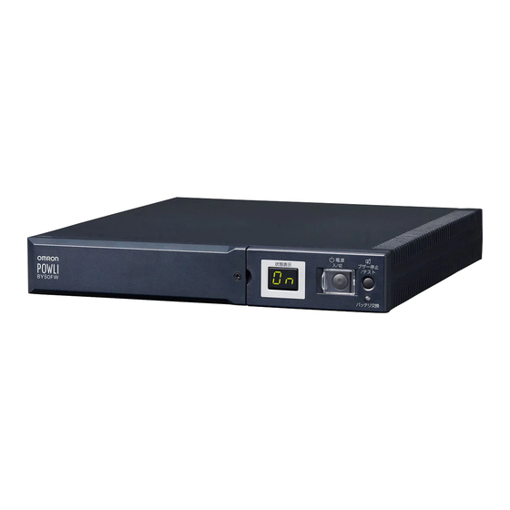
Uninterruptible Power Supply (UPS)
Instruction Manual
• This manual gives you important information to use the this unit safely and therefore be sure to
read it before installation and use.
• Keep this manual handy at the place where you install the this unit so that you can read it
whenever necessary.
BY50FW/BY75SW
Advertisement
Table of Contents

Related Manuals for Omron POWLI BY50FW


Summary of Contents for Omron POWLI BY50FW
- Page 1 Uninterruptible Power Supply (UPS) BY50FW/BY75SW Instruction Manual • This manual gives you important information to use the this unit safely and therefore be sure to read it before installation and use. • Keep this manual handy at the place where you install the this unit so that you can read it whenever necessary.
-
Page 2: Introduction
Introduction Introduction Thank you for purchasing the POWLI BY50FW/BY75SW Uninterruptible Power Supply (UPS). This unit is a UPS designed specifically for personal computers. The UPS protects (backs up) personal computers, displays, peripherals, and so on up to a power consumption of 500VA/300W (BY50FW), 750VA/450W (BY75SW) from failures in the power supply, such as power failures and voltage variations. -
Page 3: Important Safety Instruction
IMPORTANT SAFETY INSTRUCTION 1.SAVE THESE INSTRUCTIONS. This manual contains important instruction for Model BY50FW, BY75SW. That should be followed during instruction of the UPS and batteries. 2.SYMBOL This symbol indicates earth ground. This symbol indicates turning on UPS. This symbol indicates turning off UPS. 3.INTERNAL BATTERY Internal battery is Lead-acid type. - Page 4 Procedure from installation to operation Read “Safety precautions” Start Pages 4 – 10 Remove the product from the package and check the contents Page 11 Installation/connection Perform installation and connection Page 15 Are you "Using the UPS monitoring using UPS monitoring software and contact signal"...
-
Page 5: Table Of Contents
Table of Contents Table of Contents Introduction ............................... 1 IMPORTANT SAFETY INSTRUCTION ....................... 1 Safety precautions ............................4 1. Preparation ..............................11 Checking the contents ........................11 Part names ............................12 Explanation of symbol used on unit ....................14 2. Installation and connection ........................15 Precautions and notes on installation and connection .............. -
Page 6: Safety Precautions
Safety precautions Important information for safe operation is described. Safety precautions Be sure to read it before installation and start of use. The safety symbols and their meaning used in this manual are as follows: Warning Misuse may cause death or serious injury. Caution Misuse may cause injury or property damage. - Page 7 Safety precautions Caution (for installation and connection) Do not connect devices such as dryers, which have a half-wave rectifier where only half-cycles of the AC power flows. Overcurrent may damage the UPS. Connect the unit to a wall outlet (commercial power) with a current capacity of 12A or more.
- Page 8 Safety precautions Caution (for installation and connection) Do not pinch or tie the cable of the unit. Doing so may cause the cable to be damaged or heated, which may cause an electric shock or a fire. If the cable is damaged, stop using the unit and the cable must be repaired. For repair, contact us;...
- Page 9 Safety precautions Caution (for use) If you notice abnormal sound or smell, smoke, or leakage from the inside, immediately turn off the power switch and disconnect the AC input plug from a wall outlet (commercial power). Using the unit under such conditions may cause a fire. If you notice such a condition, stop using the unit and contact us at _____ for inspection and repairs.
- Page 10 Safety precautions Caution (for battery replacement) Do not drop the battery or do not give strong impact on it. Dilute sulfuric acid may leak. Do not short the battery with metal objects. Doing so could cause an electric shock, fire or burn. Some electrical energy still remains inside the spent battery.
- Page 11 Safety precautions Notes Do not connect the AC input plug of the unit to its Power Supply Output Receptacle during the Battery Mode. The unit may fail. Do not connect a page printer (laser printer, copy machine, etc.) to the unit. The Commercial Power Mode and Battery Mode are repeated frequently, which may shorten the life of the battery.
- Page 12 Safety precautions Notes Take measures for handling unforeseen accidents, such as data backup and system redundancy. The output may stop when there is a circuit failure. In the event you transfer or sell this unit to a third party, please include all of the documentation that came with the unit.
-
Page 13: Preparation
Instruction manual (Japanese and English versions) 1 each 1 each Warranty card User registration card 3P-2P conversion adaptor Label (How to determine operating status) Omron contact info label Rubber feet None Vertical stand 1 set (2 pieces) None Remote ON/OFF connector... -
Page 14: Part Names
1. Preparation 1-2 Part names BY50F Front view Digital status indicator Beep stop/test switch Battery replacement indication lamp Power switch Battery replacement cover Rear view Dip switch USB communication connector Remote ON/OFF connector Serial/Dry contact communication connector Grounding terminal AC input cable/plug Power supply output receptacle AC input overcurrent protection Communication method selection... -
Page 15: Front View
1. Preparation BY75SW Front view Battery replacement indication lamp Beep stop/test switch Power switch Digital status indicator Battery replacement cover Rear view Dip switch USB communication connector Remote ON/OFF connector Communication method Serial/Dry contact communication selection switch connector Grounding terminal Power supply output receptacle AC input cable/plug AC input overcurrent protection... -
Page 16: Explanation Of Symbol Used On Unit
1. Preparation 1-3 Explanation of symbol used on unit Symbol Description Start the UPS. Stop the UPS. Suspend a beep. -
Page 17: Installation And Connection
2. Installation and connection 2. Installation and connection 2-1 Precautions and notes on installation and connection Caution (for installation and connection) Carry the unit considering its weight and balance, and place it on a stable and robust base. Dropping or toppling the unit may cause injury. The weight of this unit is approximately: 5.3 kg (BY50FW)/ 8.7 kg (BY75SW). - Page 18 2. Installation and connection Caution (for installation and connection) When installing the unit vertically, do not put any object on it. When installing the unit horizontally, do not put any object heavier than 25kg. Doing so may cause distortion of/damage to the case, which may cause a fire. When replacing the battery, remove objects that have been placed on the unit.
- Page 19 2. Installation and connection Notes When storing the unit, charge the battery for at least 12 hours and turn off the power switch. Even if the unit is not used, the battery gradually discharges, and if it is left for a long time, it goes into an over discharge state.
-
Page 20: Installation And Connection (By50Fw)
2. Installation and connection 2-2 Installation and connection (BY50FW) Connection to back up your computer and peripherals Note Before installing this device, make a record of the serial number of this device. The serial number is required when contacting us about the device. The serial number is written in the label on the unit. - Page 21 2. Installation and connection Do not position the unit in the ways shown below. Front panel facing Front panel facing upward downward Front panel Vertical (Right side at bottom) Front panel Upside down Do not use it in a condition listed below.
-
Page 22: Installation And Connection (By75Sw)
2. Installation and connection (4) When the installation and connection are complete, connect the AC input plug of this unit to a wall outlet (commercial power). When you connect the AC input plug of this unit to a wall outlet (commercial power), battery charging automatically starts regardless of the on/off state of the Power Switch and charging completes within 12 hours. - Page 23 2. Installation and connection (2) Install the unit. Write the usage start date on the label on the side. Also, by using the included UPS monitoring software, possible to keep a record of usage start date by the software. Do not use this unit in any position other than the “proper positions” indicated in the illustration below. Vertical Proper positions Horizontal...
- Page 24 2. Installation and connection Diagram showing BY75SW mounted with anchor screws • When attaching the unit to a base plate, take the thickness of the plate cover into consideration when choosing the appropriate screws. Screw diameter: M4 Maximum screw length: 12 mm Maximum tightening torque: 1.57 N/m Proper positions Vertical...
- Page 25 2. Installation and connection (3) Connect devices that require backup to the unit’s power supply output receptacle. A total of up to 750VA (7.5A) or 450W can be connected. If the unit has an insufficient number of power output receptacles, increase the number of output receptacles by attaching a separately purchased power strip.
-
Page 26: Checking The Operation
2. Installation and connection 2-4 Checking the operation When you are complete with connecting devices to the unit, the backup function must be confirmed. Check that the Battery Mode is performed normally according to the following procedure. This operation check simulates a power failure by disconnecting the AC input plug from a wall outlet.) (1) Turn on the Power Switch of this unit. - Page 27 2. Installation and connection (5) In Battery Mode, check the LED display and a beep of the unit. Are the LED display in the same status as A or B below? indicates blinking) Status indicator Beep Output Charging Description Intermittent Backup is operating due to power failure or AC input error.
-
Page 28: Preparation For Operation
3. Preparation for operation 3. Preparation for operation 3-1 Charging the battery When you connect the AC input plug of this unit to a wall outlet (commercial power), the battery charg- ing automatically starts regardless of the on/off state of the Power Switch, and it is fully charged within 12 hours. -
Page 29: Operation
4. Operation 4. Operation 4-1 Precautions and notes on operation Caution (for use) Do not wet or pour water onto the unit. Doing so may cause an electric shock or a fire. If you wet the unit, stop using it and the unit must be inspected and/or repaired. For repair, contact us;... -
Page 30: Start And Stop Procedures And Basic Operation
4. Operation Explanation Usual operation You may either leave the power switch of the unit on (operation status) or turn it off each time when stopping the connected system. You can choose either of the operation methods for your convenience. We recom- mend turning off the power switch when you do not use connected devices for a long time. - Page 31 4. Operation Operation during a power failure • If a power failure or abnormal input power supply occurs, the UPS automatically switches to Battery Mode, continuing power output from the Power Supply Output Receptacles supplied from the battery. • The status is displayed and the beeper sounds intermittently to alert the user. Setting switch 1 can be used to turn the beeper ON/OFF.
-
Page 32: Interpreting Beeps And Displays
4. Operation 4-3 Interpreting beeps and displays 1. Displays and beeps during normal operation indicates blinking Status Battery Beep Output Charging Description Solution indicator replacement No AC input None — Operation stopped There is AC input None — Power switch “OFF” Power switch “ON”... - Page 33 4. Operation 4. Displays and beeps when there is an equipment failure (continued) indicates blinking Status Battery Beep Output Charging Description Solution indicator replacement Check that the AC input of connected devices is not short- Output stopped due to exceeded ON, or circuited, or that the Continuous...
-
Page 34: Suspending A Beep
4. Operation 4-4 Suspending a beep You can suspend a beep by pressing and holding the Beep Stop/Test Switch while a beep is sounding for 0.5 second or longer. 4-5 Description of the self-diagnostic test function You can use the following procedure to check whether a failure occurs inside the unit and whether replacing the battery is required. -
Page 35: Changing The Setting Of The Functions
4. Operation 4-7 Changing the setting of the functions 1. Selecting functions with the setting switches After changing the setting switches, turn ON the power switch again while the AC input plug is Operation connected to a wall outlet (commercial power). •... - Page 36 4. Operation Power output stop delay time setting (setting switches 5 and 6 ) … Factory- shipped setting: OFF and OFF Power output stop Setting switch 5 Setting switch 6 delay time 0 second 60 seconds 120 seconds Does not stop power output The UPS delays the power supply output stop timing.
- Page 37 4. Operation UPS stop signal setting (setting switch 7 ) … Factory-shipped setting: OFF (Only for BX50FW, BX75SW) OFF: The unit’s power output can be stopped by inputting a “High” backup power supply stop signal (BS) that continues for 10 seconds or more. The power supply output is stopped with a voltage signal input, even in commercial operation.
- Page 38 4. Operation 3. UPS operation mode settings The settings available for this operation are shown below. • Cold start ON/OFF setting When ON, it is possible to start up the unit even when there is no AC input plug. (It is not possible, however, to start up the unit by the remote signals.) •...
- Page 39 4. Operation There is AC input (when athe status indicator is ON) Normal status Power switch “OFF” (Status No. 2) <A> <B> Setting mode Cold start <C> ON/OFF setting Cold start ON: The unit can start up even when there is no AC input <C>...
- Page 40 4. Operation (A) Turn ON the power switch while the beeper stop switch is pressed. (B) Turn OFF the power switch. (C) Press and hold the beeper stop switch (for more than 1 second). (D) Press the beeper stop switch (for less than 1 second).
-
Page 41: Maintenance And Inspection
5. Maintenance and inspection 5. Maintenance and Inspection Caution (maintenance) When maintaining the connected equipment, turn OFF the power switch and disconnect the AC input plug. The backup function continues to supply power from the power output receptacles while the UPS is operating, even when the AC input plug is disconnected. -
Page 42: Replacing The Battery
5. Maintenance and inspection 5-2 Replacing the battery The battery can be replaced either while the unit is stopped (power supply output stopped) or while it is in operation (outputting power supply). Caution When the unit is used in compliance with UL standards, do not replace the battery while in operation (while power is being output). - Page 43 5. Maintenance and inspection Caution (for battery replacement) A battery can present a risk of electrical shock and high short circuit current.The following precautions should be observed when working on batteries: 1) Remove watches, rings, or other metal objects from the hands. 2) Use tools with insulated handles.
- Page 44 5. Maintenance and inspection (3) Remove the old battery, and insert the new battery. Caution Do not remove the battery by holding the cables. Pull on the white label attached to the battery, and Insert the new battery. then hold the battery with your hands to remove it. Be careful not to drop the battery.
- Page 45 5. Maintenance and inspection <After replacing the battery during operation...> Press the beeper stop/test button for 0.5 sec. to perform a self-diagnostic test. Normal operation resumes after the 10-second test. If the beeper is sounding, it will stop the first time the switch is pressed.
- Page 46 5. Maintenance and inspection (3) Hold the label stuck to the battery pack and remove it. Insert the new battery pack. Caution Do not remove the battery by holding the cables. Pull on the white label attached to the battery, Insert the new battery pack.
-
Page 47: Cleaning
5. Maintenance and inspection (5) Fit the front panel. Turn the 2 screws to secure the font panel clockwise with a screwdriver. Fit the front panel. Tighten the 2 screws. <After replacing the battery during operation...> Press the beeper stop/test button for 0.5 sec. to perform a self-diagnostic test. Normal operation resumes after the 10-second test. -
Page 48: Using The Ups Monitoring Software And Contact Signal
6. Using the UPS monitoring software and contact signal 6. Using the UPS monitoring software and contact signal * If you do not use the UPS monitoring software or contact signal, you can disregard this section. 6-1 Selecting the UPS monitoring software The following UPS monitoring software is included with the BY50FW/BY75SW: PowerAct Pro (for Windows/ Linux), UPS service driver, and UPS Power Manager (for Mac). - Page 49 Note 3: Even if the UPS does not stop when the OS is shut down, it stops automatically when the battery is depleted. Note 4: For the latest information, check our website at http://www.omron.co.jp/ese/ Note 5: Compatible CPUs: Power PC G4, Power PC G5...
-
Page 50: When Using The Included Ups Monitoring Software
6. Using the UPS monitoring software and contact signal 6-2 When using the included UPS monitoring software PowerAct Pro” UPS monitoring software Using the included “PowerAct Pro” UPS monitoring software allows you to automatically save files and shut down your computer when a power failure occurs. The schedule settings also allow you to perform your required operations, such as the UPS auto startup, auto stop, etc. - Page 51 6. Using the UPS monitoring software and contact signal Explanation Operation start using the UPS monitoring software during scheduled stop If the unit starts operation during a scheduled stop period, the next set scheduled ON operation is cancelled after the power switch is turned OFF. Auto restart after OS shutdown by UPS monitoring software In the event of a power failure, some PC models (see Note 1 below) automatically restart immediately after the completion of the OS shutdown processing by the UPS monitoring software.
- Page 52 6. Using the UPS monitoring software and contact signal “UPS Power Manager” UPS monitoring software for Mac When using Macintosh computers such as Xserve, the included “UPS Power Manager” UPS monitoring software enables you to automatically shut down the system when power failures or other input power supply problems occur.
-
Page 53: When Performing Auto-Save Functions Using The Ups Service In Windows Server 2003/Xp/2000 + Included Ups Service Driver
6. Using the UPS monitoring software and contact signal 6-3 When performing auto-save functions using the UPS service in Windows Server 2003/XP/ 2000 + included UPS service driver When using the included “UPS service driver”, the OS standard UPS service in Windows Server 2003/XP/2000 can be used. -
Page 54: When Performing Auto-Save Functions Using The Standard Ups Service In Windows Server 2003/Xp/2000/Nt
6. Using the UPS monitoring software and contact signal 6-4 When performing auto-save functions using the standard UPS service in Windows Server 2003/ XP/2000/NT When using in combination with the optional BUC26 cable, the OS standard UPS service in Windows Server 2003/XP/2000/NT can be used. - Page 55 6. Using the UPS monitoring software and contact signal 3) Click the button on the right of the "Select manufacturer (S)" window, and select "General" from the list. Click on "Custom" in the "Select model (M)" window. Click the button on the right of the "Port (P)" window, and select from the list the port that the UPS is connected to.
-
Page 56: Stopping The Ups
6. Using the UPS monitoring software and contact signal When a power failure occurs, Windows shutdown starts once the low battery level signal is detected. If the power is restored before the low battery level signal is detected, Windows shutdown does not start and the normal monitoring state is restored. - Page 57 6. Using the UPS monitoring software and contact signal 3) Click the "OK" button in the "Power supply options" window. Setup is complete. Click When a power failure occurs, Windows shutdown starts once the set time is exceeded or the low battery level signal is detected.
-
Page 58: Using The Contact Signal
6. Using the UPS monitoring software and contact signal 4) After the settings are made, double-click the "Service" icon in "Control Panels". 5) Select the UPS service and click the "Start" button. Click By starting the alerter service, messenger service, and event log service in advance, the UPS service sends warning messages to the user and records a history of events such as power failures when they occur. - Page 59 6. Using the UPS monitoring software and contact signal 2. Input of the UPS Stop Signal (BS) BS-COM UPS stops Stops the output of the UPS after the time period specified by the “power output stop delay time setting” (setting switches 5 and 6 ) has elapsed.
- Page 60 6. Using the UPS monitoring software and contact signal 6. Remote ON/OFF connector (female) (1) Connect the connector: FUPS Shutdown Disconnect the connector: FUPS Start-up (2) The corresponding warning Pin assignment Pin number Signal name Remote ON/OFF (+) Remote ON/OFF (--) Front view Screw size: Inch screw #4-40 U N C...
-
Page 61: Precautions And Notes On The Use Of The Contact Signal
6. Using the UPS monitoring software and contact signal 9. Example of the use of the Contact Signal circuit Example of the use of the BU signal TLP627 To port on PC UPS side Ω Connecting cable (twisted or System side shielded) Example of the use of the BS signal TLP521... -
Page 62: Measuring The Backup Time (Checking The Discharge Time Of The Battery)
7. Measuring the backup time (checking the discharge time of the battery) 7. Measuring the backup time (Checking the discharge time of the battery) 7-1 Measuring method of the backup time (1) Connect the AC Input Plug of the UPS to a wall outlet (commercial power) and charge it for approximately 12 hours. - Page 63 7. Measuring the backup time (checking the discharge time of the battery) (3) Calculate the initial value of the backup time for the total capacity of the connected devices from the graph below. Graph of backup time (initial value for product that has not been used) The smaller the capacity of connected devices becomes, the longer the backup time becomes.
-
Page 64: Troubleshooting
8. Troubleshooting 8. Troubleshooting Perform the checks shown below if the unit is operating abnormally. If the unit continues to operate abnormally, please contact our Electronic Systems & Equipments customer support center at _____. Problem Check and remedy UPS does not operate. 1. -
Page 65: References
Reference References A. Specifications BY50FW BY75SW Operation method Method Full-time commercial power supply method Connectable devices PC, display, and peripherals Input Nominal input voltage 100 / 110 / 115 120 VAC 100V mode Input voltage 100V mode 86 + 4 to 114 + 4 VAC 86 + 4 to 114 + 4 VAC range 110V mode... -
Page 66: Related Products
Reference B. Related products BY50FW BY75SW Spare battery pack BXB50F BXB75S Attachment fittings BXP50F — Rack mounting brackets BYP50F —... -
Page 67: Dimensional Outline Drawing (Unit: Mm)
Reference C. Dimensional outline drawing BY50FW Serial communication cable (approx. 2.2m) USB communication cable (approx. 2m) Power cable (approx. 1.8m) (unit : mm / Tolerance : ±1mm) BY75SW Serial communication cable (approx. 2.2m) USB communication cable (approx. 2m) (unit : mm / Tolerance : ± 1mm) Power cable (approx. -
Page 68: Circuit Block Diagram
Reference D. Circuit block diagram This UPS outputs power input from commercial power as it is and charges the battery at the same time. If a power failure or voltage variation occurs, the UPS automatically switches to operation using the battery and continues power output. - Page 69 No part or whole of this manual may be reproduced without permission. The contents of this manual are subject to change without notice. OMRON Corporation K1L-D-06025D...