ZyXEL Communications ES-2024 Series User Manual
Ethernet switch
Hide thumbs
Also See for ES-2024 Series:
- User manual (310 pages) ,
- Support notes (74 pages) ,
- Quick start manual (43 pages)

Related Manuals for ZyXEL Communications ES-2024 Series


Summary of Contents for ZyXEL Communications ES-2024 Series
- Page 1 ES-2024 Series Ethernet Switch User’s Guide Version 3.90 11/2008 Edition 3 DEFAULT LOGIN IP Address http://192.168.1.1 User Name admin Password 1234 www.zyxel.com www.zyxel.com...
-
Page 3: About This User's Guide
Help us help you. Send all User Guide-related comments, questions or suggestions for improvement to the following address, or use e-mail instead. Thank you! The Technical Writing Team, ZyXEL Communications Corp., 6 Innovation Road II, Science-Based Industrial Park, Hsinchu, 300, Taiwan. E-mail: techwriters@zyxel.com.tw ES-2024 Series User’s Guide... -
Page 4: Document Conventions
“k” for kilo may denote “1000” or “1024”, “M” for mega may denote “1000000” or “1048576” and so on. • “e.g.,” is a shorthand for “for instance”, and “i.e.,” means “that is” or “in other words”. ES-2024 Series User’s Guide... - Page 5 Icons Used in Figures Figures in this User’s Guide may use the following generic icons. The Switch icon is not an exact representation of your device. Switch Computer Notebook computer Server DSLAM Firewall Telephone Switch Router ES-2024 Series User’s Guide...
-
Page 6: Safety Warnings
• Do NOT obstruct the device ventilation slots, as insufficient airflow may harm your device. • The PoE (Power over Ethernet) devices that supply or receive power and their connected Ethernet cables must all be completely indoors. ES-2024 Series User’s Guide... - Page 7 Safety Warnings This product is recyclable. Dispose of it properly. ES-2024 Series User’s Guide...
- Page 8 Safety Warnings ES-2024 Series User’s Guide...
-
Page 9: Table Of Contents
Multicast ..........................143 AAA ............................157 IP Source Guard ........................171 Loop Guard ..........................181 IP Application ........................185 Static Route ..........................187 Differentiated Services ......................191 DHCP ............................195 Management ......................... 201 Maintenance ..........................203 ES-2024 Series User’s Guide... - Page 10 Contents Overview Access Control ........................209 Diagnostic ..........................227 Syslog ............................229 Cluster Management ....................... 233 MAC Table ..........................239 ARP Table ..........................243 Configure Clone ........................245 Appendices and Index ......................247 ES-2024 Series User’s Guide...
-
Page 11: Table Of Contents
2.2.2 Attaching the Mounting Brackets to the Switch ............36 2.2.3 Mounting the Switch on a Rack .................. 37 Chapter 3 Hardware Overview......................... 39 3.1 Front Panel Connection ....................... 39 3.1.1 Console Port ......................40 3.1.2 Ethernet Ports ......................40 ES-2024 Series User’s Guide... - Page 12 6.1.2 Creating a VLAN ......................61 6.1.3 Configuring DHCP Relay ................... 64 6.1.4 Troubleshooting ......................65 Chapter 7 System Status and Port Statistics ..................67 7.1 Overview ..........................67 7.2 Port Status Summary ...................... 67 7.2.1 Status: Port Details ....................68 ES-2024 Series User’s Guide...
- Page 13 Static MAC Forwarding......................99 10.1 Overview ..........................99 10.2 Configuring Static MAC Forwarding ................99 Chapter 11 Static Multicast Forwarding ....................101 11.1 Static Multicast Forwarding Overview ................101 11.2 Configuring Static Multicast Forwarding ................102 ES-2024 Series User’s Guide...
- Page 14 17.4 Link Aggregation Setting ....................129 17.5 Link Aggregation Control Protocol ................130 17.6 Static Trunking Example ....................131 Chapter 18 Port Authentication....................... 133 18.1 Port Authentication Overview ..................133 18.1.1 IEEE 802.1x Authentication ................... 133 ES-2024 Series User’s Guide...
- Page 15 22.1 Authentication, Authorization and Accounting (AAA) ............. 157 22.1.1 Local User Accounts ....................157 22.1.2 RADIUS and TACACS+ ..................158 22.2 AAA Screens ........................158 22.2.1 RADIUS Server Setup ..................158 22.2.2 TACACS+ Server Setup ..................160 ES-2024 Series User’s Guide...
- Page 16 26.1 DiffServ Overview ......................191 26.1.1 DSCP and Per-Hop Behavior ................191 26.1.2 DiffServ Network Example ..................192 26.2 Activating DiffServ ......................192 26.3 DSCP-to-IEEE 802.1p Priority Settings ..............193 26.3.1 Configuring DSCP Settings ..................194 Chapter 27 DHCP............................195 ES-2024 Series User’s Guide...
- Page 17 29.3.2 Supported MIBs ....................211 29.3.3 SNMP Traps ......................211 29.3.4 Configuring SNMP ....................214 29.3.5 Configuring SNMP Trap Group ................216 29.3.6 Setting Up Login Accounts ................. 217 29.4 SSH Overview ......................... 219 29.5 How SSH works ....................... 219 ES-2024 Series User’s Guide...
- Page 18 Chapter 34 ARP Table ..........................243 34.1 ARP Table Overview ....................... 243 34.1.1 How ARP Works ....................243 34.2 Viewing the ARP Table ....................243 Chapter 35 Configure Clone ........................245 35.1 Configure Clone ......................245 ES-2024 Series User’s Guide...
- Page 19 Table of Contents Part VI: Appendices and Index ............247 Appendix A Product Specifications..................249 Appendix B IP Addresses and Subnetting ................257 Appendix C Legal Information ....................265 Appendix D Customer Support..................... 269 Index............................275 ES-2024 Series User’s Guide...
- Page 20 Table of Contents ES-2024 Series User’s Guide...
-
Page 21: List Of Figures
Figure 34 Basic Setting > Switch Setup ....................76 Figure 35 Basic Setting > IP Setup ......................78 Figure 36 Basic Setting > Port Setup ....................80 Figure 37 Powered Device Examples ....................81 Figure 38 Basic Setting > PoE Status ....................82 ES-2024 Series User’s Guide... - Page 22 Figure 79 Advanced Application > Multicast > Multicast Setting > IGMP Snooping VLAN ....147 Figure 80 Advanced Application > Multicast > Multicast Setting > IGMP Filtering Profile ....148 Figure 81 MVR Network Example ....................... 150 ES-2024 Series User’s Guide...
- Page 23 Figure 120 Management > Maintenance ..................... 203 Figure 121 Load Factory Default: Start ....................204 Figure 122 Reboot System: Confirmation ................... 205 Figure 123 Management > Maintenance > Firmware Upgrade ............205 Figure 124 Management > Maintenance > Restore Configuration ............206 ES-2024 Series User’s Guide...
- Page 24 Figure 151 Management > Configure Clone ..................245 Figure 152 DC Power Plug ........................249 Figure 153 Network Number and Host ID .................... 258 Figure 154 Subnetting Example: Before Subnetting ................260 Figure 155 Subnetting Example: After Subnetting ................261 ES-2024 Series User’s Guide...
-
Page 25: List Of Tables
Table 36 Advanced Application > Link Aggregation > Link Aggregation Setting ......... 129 Table 37 Advanced Application > Link Aggregation > Link Aggregation Setting > LACP ....131 Table 38 Advanced Application > Port Authentication > 802.1x ............135 ES-2024 Series User’s Guide... - Page 26 Table 76 General Commands for GUI-based FTP Clients ..............208 Table 77 Access Control Overview ...................... 209 Table 78 SNMP Commands ........................ 210 Table 79 SNMP System Traps ......................211 Table 80 SNMP Interface Traps ......................212 Table 81 AAA Traps ..........................213 ES-2024 Series User’s Guide...
- Page 27 Table 110 Subnet 3 ..........................262 Table 111 Subnet 4 ..........................262 Table 112 Eight Subnets ........................262 Table 113 24-bit Network Number Subnet Planning ................263 Table 114 16-bit Network Number Subnet Planning ................263 ES-2024 Series User’s Guide...
- Page 28 List of Tables ES-2024 Series User’s Guide...
-
Page 29: Introduction
Introduction Getting to Know Your Switch (31) Hardware Installation and Connection (35) Hardware Overview (39) -
Page 31: Getting To Know Your Switch
Switch’s port or connect other switches to the Switch. In this example, all computers can share high-speed applications on the server. To expand the network, simply add more networking devices such as switches, routers, computers, print servers etc. Figure 1 Backbone Application ES-2024 Series User’s Guide... -
Page 32: Bridging Example
ATM at much lower cost while still being able to use existing adapters and switches. Moreover, the current LAN structure can be retained as all ports can freely communicate with each other. ES-2024 Series User’s Guide... -
Page 33: Ieee 802.1Q Vlan Application Examples
Shared resources such as a server can be used by all ports in the same VLAN as the server. In the following figure only ports that need access to the server need to be part of VLAN 1. Ports can belong to other VLAN groups too. Figure 4 Shared Server Using VLAN Example ES-2024 Series User’s Guide... -
Page 34: Ways To Manage The Switch
If you forget your password, you will have to reset the Switch to its factory default settings. If you backed up an earlier configuration file, you would not have to totally re-configure the Switch. You could simply restore your last configuration. ES-2024 Series User’s Guide... -
Page 35: Hardware Installation And Connection
5 Attach the rubber feet to each corner on the bottom of the Switch. These rubber feet help protect the Switch from shock or vibration and ensure space between devices when stacking. Figure 5 Attaching Rubber Feet ES-2024 Series User’s Guide... -
Page 36: Mounting The Switch On A Rack
1 Position a mounting bracket on one side of the Switch, lining up the four screw holes on the bracket with the screw holes on the side of the Switch. Figure 6 Attaching the Mounting Brackets ES-2024 Series User’s Guide... -
Page 37: Mounting The Switch On A Rack
2 Using a #2 Philips screwdriver, install the M5 flat head screws through the mounting bracket holes into the rack. 3 Repeat steps to attach the second mounting bracket on the other side of the rack. ES-2024 Series User’s Guide... - Page 38 Chapter 2 Hardware Installation and Connection ES-2024 Series User’s Guide...
-
Page 39: Hardware Overview
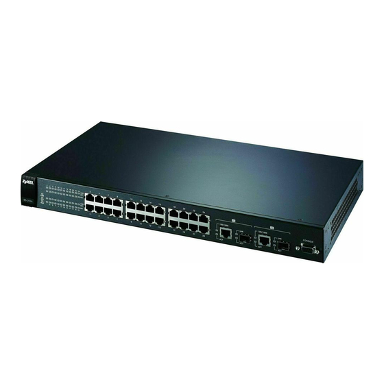
The figure below shows the front panel of the Switch. Figure 8 Front Panel: ES-2024A Console Port Gigabit Ethernet/ 10/100 Mbps Ethernet Ports Mini-GBIC Ports Figure 9 Front Panel: ES-2024PWR Console Port Gigabit Ethernet/ 10/100 Mbps Ethernet Ports Mini-GBIC Ports ES-2024 Series User’s Guide... -
Page 40: Console Port
An auto-crossover (auto-MDI/MDI-X) port automatically works with a straight-through or crossover Ethernet cable. 3.1.2.1 Default Ethernet Settings The factory default negotiation settings for the Ethernet ports on the Switch are: • Speed: Auto • Duplex: Auto • Flow control: off ES-2024 Series User’s Guide... -
Page 41: Mini-Gbic Slots
3 The Switch automatically detects the installed transceiver. Check the LEDs to verify that it is functioning properly. Figure 11 Installed Transceiver 3.1.3.2 Transceiver Removal Use the following steps to remove a mini GBIC transceiver (SFP module). 1 Open the transceiver’s latch (latch styles vary). ES-2024 Series User’s Guide... -
Page 42: Rear Panel
Make sure you are using the correct power source as shown on the panel. To connect the power to the Switch, insert the female end of power cord to the power receptacle on the rear panel. Connect the other end of the supplied power cord to the power source. ES-2024 Series User’s Guide... -
Page 43: Leds
The link to an Ethernet network is down. Mini-GBIC Ports Green The port has a successful connection. No Ethernet device is connected to this port. Green Blinking The port is sending or receiving data. The port is not sending or receiving data. ES-2024 Series User’s Guide... - Page 44 Chapter 3 Hardware Overview ES-2024 Series User’s Guide...
-
Page 45: Basic Configuration
Basic Configuration The Web Configurator (47) Initial Setup Example (57) Tutorials (61) System Status and Port Statistics (67) Basic Setting (71) -
Page 47: The Web Configurator
3 The login screen appears. The default username is admin and associated default password is 1234. The date and time display as shown if you have not configured a time server nor manually entered a time and date in the General Setup screen. Figure 16 Web Configurator: Login ES-2024 Series User’s Guide... -
Page 48: The Status Screen
C - Click this link to go to the status page of the Switch. D - Click this link to logout of the web configurator. E - Click this link to display web help pages. The help pages provide descriptions for all of the configuration screens. ES-2024 Series User’s Guide... -
Page 49: Table 3 Navigation Panel Sub-Links Overview
Chapter 4 The Web Configurator In the navigation panel, click a main link to reveal a list of submenu links. Table 3 Navigation Panel Sub-links Overview ADVANCED BASIC SETTING IP APPLICATION MANAGEMENT APPLICATION ES-2024 Series User’s Guide... -
Page 50: Table 4 Web Configurator Screen Sub-Links Details
Port Security Queuing Method Multicast Multicast Setting IGMP Snooping VLAN IGMP Filtering Profile Group Configuration RADIUS Server Setup TACACS+ Server Setup AAA Setup IP Source Guard Static Binding ARP Inspection Status LogStatus Configure Port VLAN Loop Guard ES-2024 Series User’s Guide... -
Page 51: Table 5 Navigation Panel Links
This link takes you to a screen where you can configure authentication and accounting services via external servers. The external servers can be either RADIUS (Remote Authentication Dial-In User Service) or TACACS+ (Terminal Access Controller Access-Control System Plus). ES-2024 Series User’s Guide... -
Page 52: Change Your Password
This link takes you to a screen where you can copy attributes of one port to other ports. 4.3.1 Change Your Password After you log in for the first time, it is recommended you change the default administrator password. Click Management > Access Control > Logins to display the next screen. ES-2024 Series User’s Guide... -
Page 53: Saving Your Configuration
Switch. 3 Filter all traffic to the CPU port. 4 Disable all ports. 5 Misconfigure the text configuration file. 6 Forget the password and/or IP address. 7 Prevent all services from accessing the Switch. ES-2024 Series User’s Guide... -
Page 54: Resetting The Switch
Enter Debug Mode 5 Wait for the “ ” message before activating XMODEM Starting XMODEM upload upload on your terminal. 6 After a configuration file upload, type to restart the Switch. atgo An example is shown below. ES-2024 Series User’s Guide... -
Page 55: Logging Out Of The Web Configurator
Figure 20 Web Configurator: Logout Screen 4.8 Help The web configurator’s online help has descriptions of individual screens and some supplementary information. Click the Help link from a web configurator screen to view an online help description of that screen. ES-2024 Series User’s Guide... - Page 56 Chapter 4 The Web Configurator ES-2024 Series User’s Guide...
-
Page 57: Initial Setup Example
VLANs confine broadcast frames to the VLAN group in which the port(s) belongs. You can do this with port-based VLAN or tagged static VLAN with fixed port members. In this example, you want to configure port 10 as a member of VLAN 2. Figure 21 Initial Setup Network Example: VLAN ES-2024 Series User’s Guide... -
Page 58: Setting Port Vid
VLAN group that the tag defines. In the example network, configure 2 as the port VID on port 10 so that any untagged frames received on that port get sent to VLAN 2. ES-2024 Series User’s Guide... -
Page 59: Configuring Switch Management Ip Address
The default management IP address of the Switch is 192.168.1.1. You can configure another IP address in a different subnet for management purposes. The following figure shows an example. Figure 23 Initial Setup Example: Management IP Address ES-2024 Series User’s Guide... - Page 60 3 In the VID field, enter the ID of the VLAN group to which you want this management IP address to belong. This is the same as the VLAN ID you configure in the Static VLAN screen. 4 Click Add. ES-2024 Series User’s Guide...
-
Page 61: Tutorials
VLAN ID and port number in the DHCP request. Client A connects to the Switch’s port 2 in VLAN 102. Figure 24 Tutorial: DHCP Relay Scenario 6.1.2 Creating a VLAN Follow the steps below to configure port 2 as a member of VLAN 102. ES-2024 Series User’s Guide... -
Page 62: Figure 25 Tutorial: Set Vlan Type To 802.1Q
6 Clear the TX Tagging check box to set the Switch to remove VLAN tags before sending. 7 Click Add to save the settings to the run-time memory. Settings in the run-time memory are lost when the Switch’s power is turned off. ES-2024 Series User’s Guide... -
Page 63: Figure 26 Tutorial: Create A Static Vlan
9 Enter 102 in the PVID field for port 2 to add a tag to incoming untagged frames received on that port so that the frames are forwarded to the VLAN group that the tag defines. 10 Click Apply to save your changes back to the run-time memory. ES-2024 Series User’s Guide... -
Page 64: Configuring Dhcp Relay
3 Enter the DHCP server’s IP address (192.168.2.3 in this example) in the Remote DHCP Server 1 field. 4 Select the Option 82 and the Information check boxes. 5 Click Apply to save your changes back to the run-time memory. Figure 29 Tutorial: Set DHCP Server and Relay Information ES-2024 Series User’s Guide... -
Page 65: Troubleshooting
2 You configured the correct VLAN ID, port number and system name for DHCP relay on both the DHCP server and the Switch. 3 You clicked the Save link on the Switch to have your settings take effect. ES-2024 Series User’s Guide... - Page 66 Chapter 6 Tutorials ES-2024 Series User’s Guide...
-
Page 67: System Status And Port Statistics
This identifies the Ethernet port. Click a port number to display the Port Details screen (refer to Figure 31 on page 69). Name This is the name you assigned to this port in the Basic Setting, Port Setup screen. ES-2024 Series User’s Guide... -
Page 68: Status: Port Details
7.2.1 Status: Port Details Click a number in the Port column in the Status screen to display individual port statistics. Use this screen to check status and detailed performance data about an individual port on the Switch. ES-2024 Series User’s Guide... -
Page 69: Figure 31 Status: Port Details
This field shows the number kilobytes per second transmitted on this port. Rx KB/s This field shows the number of kilobytes per second received on this port. Up Time This field shows the total amount of time the connection has been up. ES-2024 Series User’s Guide... - Page 70 This field shows the number of packets (including bad packets) received that were 1518 between 1024 and 1518 octets in length. Giant This field shows the number of packets dropped because they were bigger than the maximum frame size. ES-2024 Series User’s Guide...
-
Page 71: Basic Setting
8.2 System Information In the navigation panel, click Basic Setting > System Info to display the screen as shown. You can check the firmware version number and monitor the Switch temperature, fan speeds and voltage in this screen. ES-2024 Series User’s Guide... -
Page 72: Figure 32 Basic Setting > System Info
Current This field displays this fan's current speed in Revolutions Per Minute (RPM). This field displays this fan's maximum speed measured in Revolutions Per Minute (RPM). ES-2024 Series User’s Guide... -
Page 73: General Setup
Use this screen to configure general settings such as the system name and time. Click Basic Setting and General Setup in the navigation panel to display the screen as shown. Figure 33 Basic Setting > General Setup ES-2024 Series User’s Guide... -
Page 74: Table 8 Basic Setting > General Setup
(1 A.M. GMT or UTC). So in the European Union you would select Last, Sunday, March and the last field depends on your time zone. In Germany for instance, you would select 2:00 because Germany's time zone is one hour ahead of GMT or UTC (GMT+1). ES-2024 Series User’s Guide... -
Page 75: Introduction To Vlans
Click Basic Setting and then Switch Setup in the navigation panel to display the screen as shown. The VLAN setup screens change depending on whether you choose 802.1Q or Port Based in the VLAN Type field in this screen. Refer to the chapter on VLAN. ES-2024 Series User’s Guide... -
Page 76: Figure 34 Basic Setting > Switch Setup
Priority Level (The following descriptions are based on the traffic types defined in the IEEE 802.1d standard (which incorporates the 802.1p). ES-2024 Series User’s Guide... -
Page 77: Ip Setup
The factory default subnet mask is 255.255.255.0. Configure IP addresses for accessing and managing the Switch from the ports belonging to the pre-defined VLAN(s). See Table 102 on page 252 for how many IP addresses you can configure. ES-2024 Series User’s Guide... -
Page 78: Figure 35 Basic Setting > Ip Setup
IP Subnet Enter the IP subnet mask of your Switch in dotted decimal notation for example Mask 255.255.255.0. Default Enter the IP address of the default outgoing gateway in dotted decimal notation, for Gateway example 192.168.1.254 ES-2024 Series User’s Guide... -
Page 79: Port Setup
Click Delete to remove the selected entry from the summary table. Cancel Click Cancel to clear the Delete check boxes. 8.7 Port Setup Use this screen to configure Switch port settings. Click Basic Setting > Port Setup in the navigation panel to display the configuration screen. ES-2024 Series User’s Guide... -
Page 80: Figure 36 Basic Setting > Port Setup
When the Switch’s auto-negotiation is turned off, a port uses the pre- configured speed and duplex mode when making a connection, thus requiring you to make sure that the settings of the peer port are the same in order to connect. ES-2024 Series User’s Guide... -
Page 81: Poe Status
In the figure below, the IP camera and IP phone get their power directly from the Switch. Aside from minimizing the need for cables and wires, PoE removes the hassle of trying to find a nearby electric outlet to power up devices. Figure 37 Powered Device Examples ES-2024 Series User’s Guide... -
Page 82: Figure 38 Basic Setting > Poe Status
This field shows which ports can receive power from the Switch. You can set this in Section 8.8.1 on page • Disable - The PD connected to this port cannot get power supply. • Enable - The PD connected to this port can receive power. ES-2024 Series User’s Guide... -
Page 83: Poe Setup
8.8.1 PoE Setup Use this screen to set the priority levels for the Switch in distributing power to PDs. Click the PoE Setup link in the Basic Setting > PoE Status screen. The following screen opens. ES-2024 Series User’s Guide... -
Page 84: Figure 39 Basic Setting > Poe Setup
Save link on the top navigation panel to save your changes to the non-volatile memory when you are done configuring. Cancel Click Cancel to begin configuring this screen afresh. ES-2024 Series User’s Guide... -
Page 85: Advanced Setup
Advanced Setup VLAN (87) Static MAC Forwarding (99) Static Multicast Forwarding (101) Filtering (105) Spanning Tree Protocol (107) Bandwidth Control (121) Broadcast Storm Control (123) Mirroring (125) Link Aggregation (127) Port Authentication (133) Port Security (137) Queuing Method (141) Multicast (143) AAA (157) IP Source Guard (171) Loop Guard (181) -
Page 87: Vlan
A broadcast frame (or a multicast frame for a multicast group that is known by the system) is duplicated only on ports that are members of the VID (except the ingress port itself), thus confining the broadcast to a specific domain. ES-2024 Series User’s Guide... -
Page 88: Automatic Vlan Registration
You may choose to accept both tagged and untagged Type incoming frames, just tagged incoming frames or just untagged incoming frames on a port. Ingress filtering If set, the Switch discards incoming frames for VLANs that do not have this port as a member ES-2024 Series User’s Guide... -
Page 89: Port Vlan Trunking
• sent to a group whether it has a VLAN tag or not. • blocked from a VLAN group regardless of its VLAN tag. You can also tag all outgoing frames (that were previously untagged) from a port with the specified VID. ES-2024 Series User’s Guide... -
Page 90: Static Vlan Status
Use this screen to view detailed port settings and status of the VLAN group. See Section 9.1 on page 87 for more information on static VLAN. Click on an index number in the VLAN Status screen to display VLAN details. ES-2024 Series User’s Guide... -
Page 91: Configure A Static Vlan
Use this screen to configure and view 802.1Q VLAN parameters for the Switch. See Section 9.1 on page 87 for more information on static VLAN. To configure a static VLAN, click Static VLAN in the VLAN Status screen to display the screen as shown next. ES-2024 Series User’s Guide... -
Page 92: Figure 44 Advanced Application > Vlan > Static Vlan
Click Add to save your changes to the Switch’s run-time memory. The Switch loses these changes if it is turned off or loses power, so use the Save link on the top navigation panel to save your changes to the non-volatile memory when you are done configuring. ES-2024 Series User’s Guide... -
Page 93: Configure Vlan Port Settings
Select this check box to permit VLAN groups beyond the local Switch. Ingress Check Select this check box to activate ingress filtering on the Switch. Clear this check box to disable ingress filtering the Switch. Port This field displays the port number. ES-2024 Series User’s Guide... -
Page 94: Port-Based Vlan Setup
Port-based VLANs are specific only to the Switch on which they were created. When you activate port-based VLAN, the Switch uses a default VLAN ID of 1. You cannot change it. ES-2024 Series User’s Guide... -
Page 95: Configure A Port-Based Vlan
Select Port Based as the VLAN Type in the Switch Setup screen and then click VLAN from the navigation panel to display the next screen. Figure 46 Advanced Application > VLAN: Port Based VLAN Setup (All Connected) ES-2024 Series User’s Guide... -
Page 96: Figure 47 Advanced Application > Vlan: Port Based Vlan Setup (Port Isolation)
Chapter 9 VLAN Figure 47 Advanced Application > VLAN: Port Based VLAN Setup (Port Isolation) ES-2024 Series User’s Guide... -
Page 97: Table 19 Advanced Application > Vlan: Port Based Vlan Setup
Save link on the top navigation panel to save your changes to the non-volatile memory when you are done configuring. Cancel Click Cancel to begin configuring this screen afresh. ES-2024 Series User’s Guide... - Page 98 Chapter 9 VLAN ES-2024 Series User’s Guide...
-
Page 99: Static Mac Forwarding
Chapter 19 on page 137 for more information on port security. Click Advanced Applications > Static MAC Forwarding in the navigation panel to display the configuration screen as shown. Figure 48 Advanced Application > Static MAC Forwarding ES-2024 Series User’s Guide... -
Page 100: Table 20 Advanced Application > Static Mac Forwarding
This field displays the port where the MAC address shown in the next field will be forwarded. Delete Click Delete to remove the selected entry from the summary table. Cancel Click Cancel to clear the Delete check boxes. ES-2024 Series User’s Guide... -
Page 101: Static Multicast Forwarding
3. Figure 51 shows frames being forwarded to ports 2 and 3 within VLAN group 4. Figure 49 No Static Multicast Forwarding Figure 50 Static Mutlicast Forwarding to A Single Port ES-2024 Series User’s Guide... -
Page 102: Configuring Static Multicast Forwarding
03:00:5e:00:00:27 are valid multicast MAC addresses. You can forward frames with matching destination MAC address to port(s) within a VLAN group. Enter the ID that identifies the VLAN group here. If you don’t have a specific target VLAN, enter 1. ES-2024 Series User’s Guide... - Page 103 This field displays the port(s) within a identified VLAN group to which frames containing the specified multicast MAC address will be forwarded. Delete Click Delete to remove the selected entry from the summary table. Cancel Click Cancel to clear the Delete check boxes. ES-2024 Series User’s Guide...
- Page 104 Chapter 11 Static Multicast Forwarding ES-2024 Series User’s Guide...
-
Page 105: Filtering
Click Add to save your changes to the Switch’s run-time memory. The Switch loses these changes if it is turned off or loses power, so use the Save link on the top navigation panel to save your changes to the non-volatile memory when you are done configuring. ES-2024 Series User’s Guide... - Page 106 This field displays the VLAN group identification number. Delete Check the rule(s) that you want to remove in the Delete column and then click the Delete button. Cancel Click Cancel to clear the selected checkbox(es) in the Delete column. ES-2024 Series User’s Guide...
-
Page 107: Spanning Tree Protocol
Both RSTP and STP flush unwanted learned addresses from the filtering database. In RSTP, the port states are Discarding, Learning, and Forwarding. In this user’s guide, “STP” refers to both STP and RSTP. 13.1.1 STP Terminology The root bridge is the base of the spanning tree. ES-2024 Series User’s Guide... -
Page 108: How Stp Works
BPDU after a predefined interval (Max Age), the bridge assumes that the link to the root bridge is down. This bridge then initiates negotiations with other bridges to reconfigure the network to re-establish a valid network topology. ES-2024 Series User’s Guide... -
Page 109: Stp Port States
The following figure shows a network example where two VLANs are configured on the two switches. If the switches are using STP or RSTP, the link for VLAN 2 will be blocked as STP and RSTP allow only one link in the network and block the redundant link. ES-2024 Series User’s Guide... -
Page 110: Figure 54 Stp/Rstp Network Example
Devices that belong to the same MST region are configured to have the same MSTP configuration identification settings. These include the following parameters: • Name of the MST region • Revision level as the unique number for the MST region • VLAN-to-MST Instance mapping ES-2024 Series User’s Guide... -
Page 111: Spanning Tree Configuration Screen
Figure 57 MSTP and Legacy RSTP Network Example 13.2 Spanning Tree Configuration Screen Use this screen to select the STP mode for the Switch. To open this screen, click Advanced Application > Spanning Tree Protocol > Configuration. ES-2024 Series User’s Guide... -
Page 112: Configure Rapid Spanning Tree Protocol
Click Cancel to begin configuring this screen afresh. 13.3 Configure Rapid Spanning Tree Protocol Use this screen to configure RSTP settings, see Section 13.1 on page 107 for more information on RSTP. Click RSTP in the Advanced Application > Spanning Tree Protocol screen. ES-2024 Series User’s Guide... -
Page 113: Figure 59 Advanced Application > Spanning Tree Protocol > Rstp
(provided in the last BPDU) becomes the designated port for the attached LAN. If it is a root port, a new root port is selected from among the switch ports attached to the network. The allowed range is 6 to 40 seconds. ES-2024 Series User’s Guide... -
Page 114: Rapid Spanning Tree Protocol Status
Click Advanced Application > Spanning Tree Protocol in the navigation panel to display the status screen as shown next. See Section 13.1 on page 107 for more information on RSTP. This screen is only available after you activate RSTP on the Switch. ES-2024 Series User’s Guide... -
Page 115: Configure Multiple Spanning Tree Protocol
This is the time since the spanning tree was last reconfigured. Change 13.5 Configure Multiple Spanning Tree Protocol To configure MSTP, click MSTP in the Advanced Application > Spanning Tree Protocol screen. See Section 13.1.4 on page 109 for more information on MSTP. ES-2024 Series User’s Guide... -
Page 116: Figure 61 Advanced Application > Spanning Tree Protocol > Mstp
Status Click Status to display the MSTP Status screen (see Figure 62 on page 119). Active Select this check box to activate MSTP on the Switch. Clear this check box to disable MSTP on the Switch. ES-2024 Series User’s Guide... - Page 117 Remove - to remove this range of VLAN(s) from being mapped to the MST instance. • Clear - to remove all VLAN(s) from being mapped to this MST instance. Enabled VLAN(s) This field displays which VLAN(s) are mapped to this MST instance. Port This field displays the port number. ES-2024 Series User’s Guide...
-
Page 118: Multiple Spanning Tree Protocol Status
Click Advanced Application > Spanning Tree Protocol in the navigation panel to display the status screen as shown next. See Section 13.1.4 on page 109 for more information on MSTP. This screen is only available after you activate MSTP on the Switch. ES-2024 Series User’s Guide... -
Page 119: Figure 62 Advanced Application > Spanning Tree Protocol > Status: Mstp
This is the time (in seconds) the root switch will wait before changing states (that (second) is, listening to learning to forwarding). Cost to Bridge This is the path cost from the root port on this Switch to the root switch. ES-2024 Series User’s Guide... - Page 120 This is the path cost from the root port in this MST instance to the regional root switch. Port ID This is the priority and number of the port on the Switch through which this Switch must communicate with the root of the MST instance. ES-2024 Series User’s Guide...
-
Page 121: Bandwidth Control
The following table describes the related labels in this screen. Table 30 Advanced Application > Bandwidth Control LABEL DESCRIPTION Active Select this check box to enable bandwidth control on the Switch. Port This field displays the port number. ES-2024 Series User’s Guide... - Page 122 Save link on the top navigation panel to save your changes to the non-volatile memory when you are done configuring. Cancel Click Cancel to begin configuring this screen afresh. ES-2024 Series User’s Guide...
-
Page 123: Broadcast Storm Control
DLF packets in your network. You can specify limits for each packet type on each port. Click Advanced Application > Broadcast Storm Control in the navigation panel to display the screen as shown next. Figure 64 Advanced Application > Broadcast Storm Control ES-2024 Series User’s Guide... -
Page 124: Table 31 Advanced Application > Broadcast Storm Control
Save link on the top navigation panel to save your changes to the non-volatile memory when you are done configuring. Cancel Click Cancel to begin configuring this screen afresh. ES-2024 Series User’s Guide... -
Page 125: Mirroring
Click Advanced Application > Mirroring in the navigation panel to display the Mirroring screen. Use this screen to select a monitor port and specify the traffic flow to be copied to the monitor port. Figure 65 Advanced Application > Mirroring ES-2024 Series User’s Guide... -
Page 126: Table 32 Advanced Application > Mirroring
Save link on the top navigation panel to save your changes to the non-volatile memory when you are done configuring. Cancel Click Cancel to begin configuring this screen afresh. ES-2024 Series User’s Guide... -
Page 127: Link Aggregation
LACP also allows port redundancy, that is, if an operational port fails, then one of the “standby” ports become operational without user intervention. Please note that: ES-2024 Series User’s Guide... -
Page 128: Link Aggregation Id
These are the ports that are currently transmitting data as one logical link in this trunk Ports group. Port Priority and Port Number are 0 as it is the aggregator ID for the trunk group, not the individual port. ES-2024 Series User’s Guide... -
Page 129: Link Aggregation Setting
This is the only screen you need to configure to enable static link aggregation. Aggregation Setting Group ID The field identifies the link aggregation group, that is, one logical link containing multiple ports. Active Select this option to activate a trunk group. ES-2024 Series User’s Guide... -
Page 130: Link Aggregation Control Protocol
Click in the Advanced Application > Link Aggregation > Link Aggregation Setting > LACP to display the screen shown next. See Section 17.2 on page 127 for more information on dynamic link aggregation. Figure 68 Advanced Application > Link Aggregation > Link Aggregation Setting > LACP ES-2024 Series User’s Guide... -
Page 131: Static Trunking Example
1 Make your physical connections - make sure that the ports that you want to belong to the trunk group are connected to the same destination. The following figure shows ports 2-5 on switch A connected to switch B. ES-2024 Series User’s Guide... -
Page 132: Figure 69 Trunking Example - Physical Connections
Click Apply when you are done. Figure 70 Trunking Example - Configuration Screen Your trunk group 1 (T1) configuration is now complete; you do not need to go to any additional screens. ES-2024 Series User’s Guide... -
Page 133: Port Authentication
At the time of writing, IEEE 802.1x is not supported by all operating systems. See your operating system documentation. If your operating system does not support 802.1x, then you may need to install 802.1x client software. ES-2024 Series User’s Guide... -
Page 134: Port Authentication Configuration
Figure 72 Advanced Application > Port Authentication 18.2.1 Activate IEEE 802.1x Security Use this screen to activate IEEE 802.1x security. In the click Port Authentication screen 802.1x to display the configuration screen as shown. ES-2024 Series User’s Guide... -
Page 135: Figure 73 Advanced Application > Port Authentication > 802.1X
Save link on the top navigation panel to save your changes to the non-volatile memory when you are done configuring. Cancel Click Cancel to begin configuring this screen afresh. ES-2024 Series User’s Guide... - Page 136 Chapter 18 Port Authentication ES-2024 Series User’s Guide...
-
Page 137: Port Security
The Switch supports five possible configurations for port security. See Section 19.3 on page 139 for supported configurations and an example. 19.2 Port Security Setup Click Advanced Application > Port Security in the navigation panel to display the screen as shown. ES-2024 Series User’s Guide... -
Page 138: Figure 74 Advanced Application > Port Security
Address MAC address learning reduces outgoing broadcast traffic. For MAC address Learning learning to occur on a port, the port itself must be active (activated in the Basic Settings, Port Setup screen) with address learning enabled. ES-2024 Series User’s Guide... -
Page 139: Port Security Example
• Port 4 - Drop all packets from unknown MAC addresses and do not learn MAC addresses. • Port 5 - Drop all packets from unknown MAC addresses but forward packets from up to 100 learned MAC addresses. ES-2024 Series User’s Guide... -
Page 140: Figure 75 Port Security Example
Drop all packets from unknown MAC addresses, do not learn MAC addresses. Drop all packets from unknown MAC addresses, do not learn MAC addresses. Drop packets from unknown MAC addresses, learn up to 100 MAC addresses. ES-2024 Series User’s Guide... -
Page 141: Queuing Method
This works in a looping fashion until a queue is empty. ES-2024 Series User’s Guide... -
Page 142: Configuring Queuing
Save link on the top navigation panel to save your changes to the non-volatile memory when you are done configuring. Cancel Click Cancel to begin configuring this screen afresh. ES-2024 Series User’s Guide... -
Page 143: Multicast
IP multicast hosts to learn the IP multicast group membership. It checks IGMP packets passing through it, picks out the group registration information, and configures multicasting accordingly. IGMP snooping allows the Switch to learn multicast groups without you having to manually configure them. ES-2024 Series User’s Guide... -
Page 144: Igmp Snooping And Vlans
This field displays IP multicast group addresses. 21.3 Multicast Setting Click Advanced Applications > Multicast > Multicast Setting link to display the screen as shown. See Section 21.1 on page 143 for more information on multicasting. ES-2024 Series User’s Guide... -
Page 145: Figure 78 Advanced Application > Multicast > Multicast Setting
Specify the action to perform when the Switch receives an unknown multicast Multicast Frame frame. Select Drop to discard the frame(s). Select Flooding to send the frame(s) to all ports. Port This field displays the port number. ES-2024 Series User’s Guide... - Page 146 Save link on the top navigation panel to save your changes to the non-volatile memory when you are done configuring. Cancel Click Cancel to begin configuring this screen afresh. ES-2024 Series User’s Guide...
-
Page 147: Igmp Snooping Vlan
Enter the descriptive name of the VLAN for identification purposes. Enter the ID of a static VLAN; the valid range is between 1 and 4094. Note: You cannot configure the same VLAN ID as in the MVR screen. ES-2024 Series User’s Guide... -
Page 148: Igmp Filtering Profile
Each port can be assigned a single profile. A profile can be assigned to multiple ports. Click Advanced Applications > Multicast > Multicast Setting > IGMP Filtering Profile link to display the screen as shown. Figure 80 Advanced Application > Multicast > Multicast Setting > IGMP Filtering Profile ES-2024 Series User’s Guide... -
Page 149: Mvr Overview
The following figure shows a network example. The subscriber VLAN (1, 2 and 3) information is hidden from the streaming media server, S. In addition, the multicast VLAN information is only visible to the Switch and S. ES-2024 Series User’s Guide... -
Page 150: Types Of Mvr Ports
VLAN, the receiving port will still be on the list of forwarding destination for the multicast traffic. Otherwise, the Switch removes the receiver port from the forwarding table. ES-2024 Series User’s Guide... -
Page 151: General Mvr Configuration
You can create up to three multicast VLANs and up to 256 multicast rules on the Switch. Your Switch automatically creates a static VLAN (with the same VID) when you create a multicast VLAN in this screen. ES-2024 Series User’s Guide... -
Page 152: Figure 83 Advanced Application > Multicast > Multicast Setting > Mvr
Use this row only if you want to make some settings the same for all ports. Use this row first to set the common settings and then make adjustments on a port-by-port basis. Note: Changes in this row are copied to all the ports as soon as you make them. ES-2024 Series User’s Guide... -
Page 153: Mvr Group Configuration
Configure MVR IP multicast group address(es) in the Group Configuration screen. Click Group Configuration in the MVR screen. A port can belong to more than one multicast VLAN. However, IP multicast group addresses in different multicast VLANs cannot overlap. ES-2024 Series User’s Guide... -
Page 154: Mvr Configuration Example
VLAN 1. In addition, port 7 belongs to the multicast group with VID 200 to receive multicast traffic (the News and Movie channels) from the remote streaming media server, S. Computers A, B and C in VLAN 1 are able to receive the traffic. ES-2024 Series User’s Guide... -
Page 155: Figure 85 Mvr Configuration Example
To set the Switch to forward the multicast group traffic to the subscribers, configure multicast group settings in the Group Configuration screen. The following figure shows an example where two multicast groups (News and Movie) are configured for the multicast VLAN 200. ES-2024 Series User’s Guide... -
Page 156: Figure 87 Mvr Group Configuration Example
Chapter 21 Multicast Figure 87 MVR Group Configuration Example Figure 88 MVR Group Configuration Example ES-2024 Series User’s Guide... -
Page 157: Aaa
By storing user profiles locally on the Switch, your Switch is able to authenticate and authorize users without interacting with a network AAA server. However, there is a limit on the number of users you may authenticate in this way (See Chapter 29 on page 209). ES-2024 Series User’s Guide... -
Page 158: Radius And Tacacs
Use this screen to configure your RADIUS server settings. See Section 22.1.2 on page 158 more information on RADIUS servers. Click on the RADIUS Server Setup link in the AAA screen to view the screen as shown. ES-2024 Series User’s Guide... -
Page 159: Figure 91 Advanced Application > Aaa > Radius Server Setup
RADIUS server for 15 seconds and then tries the second RADIUS server. Index This is a read-only number representing a RADIUS server entry. IP Address Enter the IP address of an external RADIUS server in dotted decimal notation. ES-2024 Series User’s Guide... -
Page 160: Tacacs+ Server Setup
Use this screen to configure your TACACS+ server settings. See Section 22.1.2 on page 158 for more information on TACACS+ servers. Click on the TACACS+ Server Setup link in the AAA screen to view the screen as shown. ES-2024 Series User’s Guide... -
Page 161: Figure 92 Advanced Application > Aaa > Tacacs+ Server Setup
For example, if you set the timeout value to 30 seconds, then the Switch waits for a response from the first TACACS+ server for 15 seconds and then tries the second TACACS+ server. Index This is a read-only number representing a TACACS+ server entry. ES-2024 Series User’s Guide... -
Page 162: Aaa Setup
Click Cancel to begin configuring this screen afresh. 22.2.3 AAA Setup Use this screen to configure authentication and accounting settings on the Switch. Click on the AAA Setup link in the AAA screen to view the screen as shown. ES-2024 Series User’s Guide... -
Page 163: Figure 93 Advanced Application > Aaa > Aaa Setup
Method 2 and Method 3 fields. Select local to have the Switch check the access privilege configured for local authentication. Select radius or tacacs+ to have the Switch check the access privilege via the external servers. ES-2024 Series User’s Guide... - Page 164 (if it lasts past the Update Period), and when a user ends a session. • stop-only - to have the Switch send information to the accounting server only when a user ends a session. ES-2024 Series User’s Guide...
-
Page 165: Vendor Specific Attribute
VSAs for users authenticating via the RADIUS server. The following table describes the VSAs supported on the Switch. Table 53 Supported VSAs FUNCTION ATTRIBUTE Ingress Bandwidth Vendor-Id = 890 Assignment Vendor-Type = 1 Vendor-data = ingress rate (Kbps in decimal format) ES-2024 Series User’s Guide... -
Page 166: Supported Radius Attributes
Refer to RFC 2866 and RFC 2869 for RADIUS attributes used for accounting. This appendix lists the attributes used by authentication and accounting functions on the Switch. In cases where the attribute has a specific format associated with it, the format is specified. ES-2024 Series User’s Guide... -
Page 167: Attributes Used For Authentication
The following sections list the attributes sent from the Switch to the RADIUS server when performing authentication. 22.3.2.1 Attributes Used for Accounting System Events NAS-IP-Address NAS-Identifier Acct-Status-Type Acct-Session-ID - The format of Acct-Session-Id is date+time+8-digit sequential number, for example, 2007041917210300000001. (date: 2007/04/19, time: 17:21:03, serial number: 00000001) Acct-Delay-Time ES-2024 Series User’s Guide... -
Page 168: Table 55 Radius Attributes - Exec Events Via Console
The attributes are listed in the following table along with the time of the session they are sent: Table 57 RADIUS Attributes - Exec Events via Console ATTRIBUTE START INTERIM-UPDATE STOP User-Name NAS-IP-Address NAS-Port Class Called-Station-Id Calling-Station-Id NAS-Identifier ES-2024 Series User’s Guide... - Page 169 Chapter 22 AAA Table 57 RADIUS Attributes - Exec Events via Console (continued) ATTRIBUTE START INTERIM-UPDATE STOP NAS-Port-Type Acct-Status-Type Acct-Delay-Time Acct-Session-Id Acct-Authentic Acct-Input-Octets Acct-Output-Octets Acct-Session-Time Acct-Input-Packets Acct-Output-Packets Acct-Terminate-Cause Acct-Input-Gigawords Acct-Output-Gigawords ES-2024 Series User’s Guide...
- Page 170 Chapter 22 AAA ES-2024 Series User’s Guide...
-
Page 171: Ip Source Guard
23.1.1 ARP Inspection Overview Use ARP inspection to filter unauthorized ARP packets on the network. This can prevent many kinds of man-in-the-middle attacks, such as the one in the following example. Figure 94 Example: Man-in-the-middle Attack ES-2024 Series User’s Guide... - Page 172 ARP packets. 2 Enable ARP inspection on the Switch. 3 Enable ARP inspection on each VLAN. 4 Configure trusted and untrusted ports, and specify the maximum number of ARP packets that each port can receive per second. ES-2024 Series User’s Guide...
-
Page 173: Ip Source Guard
If you try to create a static binding with the same MAC address and VLAN ID as an existing static binding, the new static binding replaces the original one. To open this screen, click Advanced Application > IP Source Guard > Static Binding. ES-2024 Series User’s Guide... -
Page 174: Figure 96 Ip Source Guard Static Binding
This field displays the port number in the binding. If this field is blank, the binding applies to all ports. Delete Select this, and click Delete to remove the specified entry. Cancel Click this to clear the Delete check boxes above. ES-2024 Series User’s Guide... -
Page 175: Arp Inspection Status
Use this screen to look at log messages that were generated by ARP packets and that have not been sent to the syslog server yet. To open this screen, click Advanced Application > IP Source Guard > ARP Inspection > Log Status. ES-2024 Series User’s Guide... -
Page 176: Arp Inspection Configure
Use this screen to enable ARP inspection on the Switch. You can also configure the length of time the Switch stores records of discarded ARP packets and global settings for the ARP inspection log. To open this screen, click Advanced Application > IP Source Guard > ARP Inspection > Configure. ES-2024 Series User’s Guide... -
Page 177: Figure 99 Arp Inspection Configure
Click Clearing log status table in the ARP Inspection Log Status screen to clear the log and reset this counter. See Section 23.4.1 on page 175. ES-2024 Series User’s Guide... -
Page 178: Arp Inspection Port Configure
Use this screen to specify whether ports are trusted or untrusted ports for ARP inspection. To open this screen, click Advanced Application > IP Source Guard > ARP Inspection > Configure > Port. Figure 100 ARP Inspection Port Configure ES-2024 Series User’s Guide... -
Page 179: Arp Inspection Vlan Configure
This field displays the VLAN ID of each VLAN in the range specified above. If you configure the * VLAN, the settings are applied to all VLANs. Enabled Select Yes to enable ARP inspection on the VLAN. Select No to disable ARP inspection on the VLAN. ES-2024 Series User’s Guide... - Page 180 Switch loses these changes if it is turned off or loses power, so use the Save link on the top navigation panel to save your changes to the non- volatile memory when you are done configuring. Cancel Click this to reset the values in this screen to their last-saved values. ES-2024 Series User’s Guide...
-
Page 181: Loop Guard
• It will receive broadcast messages sent out from the switch in loop state. • It will receive its own broadcast messages that it sends out as they loop back. It will then re-broadcast those messages again. ES-2024 Series User’s Guide... -
Page 182: Figure 103 Switch In Loop State
In this example, the probe packet is sent from port N and returns on another port. As long as loop guard is enabled on port N. The Switch will shut down port N if it detects that the probe packet has returned to the Switch. Figure 105 Loop Guard - Network Loop ES-2024 Series User’s Guide... -
Page 183: Loop Guard Setup
Select this option to enable loop guard on the Switch. The Switch generates syslog, internal log messages as well as SNMP traps when it shuts down a port via the loop guard feature. Port This field displays a port number. ES-2024 Series User’s Guide... - Page 184 Save link on the top navigation panel to save your changes to the non-volatile memory when you are done configuring. Cancel Click Cancel to begin configuring this screen afresh. ES-2024 Series User’s Guide...
-
Page 185: Ip Application
IP Application Static Route (187) Differentiated Services (191) DHCP (195) -
Page 187: Static Route
R2 to send traffic to an SNMP trap server on network N2. Figure 107 Static Routing Overview 25.2 Configuring Static Routing Click IP Application > Static Routing in the navigation panel to display the screen as shown. ES-2024 Series User’s Guide... -
Page 188: Figure 108 Ip Application > Static Routing
This field displays the descriptive name for this route. This is for identification purpose only. Destination This field displays the IP network address of the final destination. Address Subnet Mask This field displays the subnet mask for this destination. ES-2024 Series User’s Guide... - Page 189 Switch that will forward the packet to the destination. Metric This field displays the cost of transmission for routing purposes. Delete Click Delete to remove the selected entry from the summary table. Cancel Click Cancel to clear the Delete check boxes. ES-2024 Series User’s Guide...
- Page 190 Chapter 25 Static Route ES-2024 Series User’s Guide...
-
Page 191: Differentiated Services
DiffServ network. Based on the marking rule different kinds of traffic can be marked for different priorities of forwarding. Resources can then be allocated according to the DSCP values and the configured policies. ES-2024 Series User’s Guide... -
Page 192: Diffserv Network Example
Figure 110 DiffServ Network 26.2 Activating DiffServ Activate DiffServ to apply marking rules or IEEE 802.1p priority mapping on the selected port(s). Click IP Application > DiffServ in the navigation panel to display the screen as shown. ES-2024 Series User’s Guide... -
Page 193: Dscp-To-Ieee 802.1P Priority Settings
26.3 DSCP-to-IEEE 802.1p Priority Settings You can configure the DSCP to IEEE 802.1p mapping to allow the Switch to prioritize all traffic based on the incoming DSCP value according to the DiffServ to IEEE 802.1p mapping table. ES-2024 Series User’s Guide... -
Page 194: Configuring Dscp Settings
Save link on the top navigation panel to save your changes to the non-volatile memory when you are done configuring. Cancel Click Cancel to begin configuring this screen afresh. ES-2024 Series User’s Guide... -
Page 195: Dhcp
• VLAN - The Switch is configured on a VLAN by VLAN basis. The Switch can be configured to relay DHCP requests to different DHCP servers for clients in different VLAN. 27.2 DHCP Status Click IP Application > DHCP in the navigation panel. The DHCP Status screen displays. ES-2024 Series User’s Guide... -
Page 196: Dhcp Relay
Table 71 Relay Agent Information FIELD LABELS DESCRIPTION Slot ID (1 byte) This value is always 0 for stand-alone switches. Port ID (1 byte) This is the port that the DHCP client is connected to. ES-2024 Series User’s Guide... -
Page 197: Configuring Dhcp Global Relay
The follow figure shows a network example where the Switch is used to relay DHCP requests for the VLAN1 and VLAN2 domains. There is only one DHCP server that services the DHCP clients in both domains. ES-2024 Series User’s Guide... -
Page 198: Configuring Dhcp Vlan Settings
DHCP Status screen that displays. You must set up a management IP address for each VLAN that you want to configure DHCP settings for on the Switch. See Section 8.6 on page 77 information on how to do this. ES-2024 Series User’s Guide... -
Page 199: Figure 117 Ip Application > Dhcp > Vlan
DHCP Status This field displays the first remote DHCP server IP address. Delete Select the configuration entries you want to remove and click Delete to remove them. Cancel Click Cancel to clear the Delete check boxes. ES-2024 Series User’s Guide... -
Page 200: Example: Dhcp Relay For Two Vlans
192.168.1.100. Requests from the academic buildings (VLAN 2) are sent to the other DHCP server with an IP address of 172.23.10.100. Figure 118 DHCP Relay for Two VLANs For the example network, configure the VLAN Setting screen as shown. Figure 119 DHCP Relay for Two VLANs Configuration Example ES-2024 Series User’s Guide... -
Page 201: Management
Management Maintenance (203) Access Control (209) Diagnostic (227) Syslog (229) Cluster Management (233) MAC Table (239) ARP Table (243) Configure Clone (245) -
Page 203: Maintenance
Click Click Here to go to the Restore Configuration screen. Configuration Backup Click Click Here to go to the Backup Configuration screen. Configuration Load Factory Click Click Here to reset the configuration to the factory default settings. Default ES-2024 Series User’s Guide... -
Page 204: Load Factory Default
Alternatively, click Save on the top right-hand corner in any screen to save the configuration changes to the current configuration. Clicking the Apply or Add button does NOT save the changes permanently. All unsaved changes are erased after you reboot the Switch. ES-2024 Series User’s Guide... -
Page 205: Reboot System
Switch and apply the new firmware immediately. (Firmware upgrades are only applied after a reboot). Click Upgrade to load the new firmware. After the firmware upgrade process is complete, see the System Info screen to verify your current firmware version number. ES-2024 Series User’s Guide... -
Page 206: Restore A Configuration File
3 Choose a location to save the file on your computer from the Save in drop-down list box and type a descriptive name for it in the File name list box. Click Save to save the configuration file to your computer. ES-2024 Series User’s Guide... -
Page 207: Ftp Command Line
1 Launch the FTP client on your computer. 2 Enter , followed by a space and the IP address of your Switch. open 3 Press [ENTER] when prompted for a username. 4 Enter your password as requested (the default is “1234”). ES-2024 Series User’s Guide... -
Page 208: Gui-Based Ftp Clients
• FTP service is disabled in the Service Access Control screen. • The IP address(es) in the Remote Management screen does not match the client IP address. If it does not match, the Switch will disconnect the Telnet session immediately. ES-2024 Series User’s Guide... -
Page 209: Access Control
See the CLI Reference Guide for more information on disabling multi- login. 29.2 The Access Control Main Screen Click Management > Access Control in the navigation panel to display the main screen as shown. Figure 126 Management > Access Control ES-2024 Series User’s Guide... -
Page 210: About Snmp
Get operation, followed by a series of GetNext operations. Allows the manager to set values for object variables within an agent. Trap Used by the agent to inform the manager of some events. ES-2024 Series User’s Guide... -
Page 211: Snmp V3 And Security
TemperatureEventOn 1.3.6.1.4.1.890.1.5.8.16.27.2.1 This trap is sent when the temperature goes above or below the normal operating range. TemperatureEventClear 1.3.6.1.4.1.890.1.5.8.27.27.2.2 This trap is sent when the temperature returns to the normal operating range. ES-2024 Series User’s Guide... -
Page 212: Table 80 Snmp Interface Traps
AutonegotiationFailedEventC 1.3.6.1.4.1.890.1.5.8.16.27.2.2 This trap is sent when an lear Ethernet interface auto- 1.3.6.1.4.1.890.1.5.8.27.27.2.2 negotiates with the peer Ethernet interface. lldp LLDPRemoteTopologyChang 1.0.8802.1.1.2.0.0.1 This trap is sent when the LLDP (Link Layer Discovery Protocol) remote topology changes. ES-2024 Series User’s Guide... -
Page 213: Table 81 Aaa Traps
1.3.6.1.2.1.80.0.3 This trap is sent when a ping test is completed. traceroute traceRouteTestFailed 1.3.6.1.2.1.81.0.2 This trap is sent when a traceroute test fails. traceRouteTestCompleted 1.3.6.1.2.1.81.0.3 This trap is sent when a traceroute test is completed. ES-2024 Series User’s Guide... -
Page 214: Configuring Snmp
This trap is sent when the variable falls below the RMON "falling" threshold. 29.3.4 Configuring SNMP From the Access Control screen, display the SNMP screen. You can click Access Control to go back to the Access Control screen. ES-2024 Series User’s Guide... -
Page 215: Figure 128 Management > Access Control > Snmp
Specify the version of the SNMP trap messages. Enter the IP addresses of up to four managers to send your SNMP traps to. Port Enter the port number upon which the manager listens for SNMP traps. ES-2024 Series User’s Guide... -
Page 216: Configuring Snmp Trap Group
29.3.5 Configuring SNMP Trap Group From the SNMP screen, click Trap Group to view the screen as shown. Use the Trap Group screen to specify the types of SNMP traps that should be sent to each SNMP manager. ES-2024 Series User’s Guide... -
Page 217: Setting Up Login Accounts
• An administrator is someone who can both view and configure Switch changes. The username for the Administrator is always admin. The default administrator password is 1234. It is highly recommended that you change the default administrator password (1234). ES-2024 Series User’s Guide... -
Page 218: Figure 130 Management > Access Control > Logins
Save link on the top navigation panel to save your changes to the non-volatile memory when you are done configuring. Cancel Click Cancel to begin configuring this screen afresh. ES-2024 Series User’s Guide... -
Page 219: Ssh Overview
The client automatically saves any new server public keys. In subsequent connections, the server public key is checked against the saved version on the client computer. ES-2024 Series User’s Guide... -
Page 220: Ssh Implementation On The Switch
1 HTTPS connection requests from an SSL-aware web browser go to port 443 (by default) on the Switch’s WS (web server). 2 HTTP connection requests from a web browser go to port 80 (by default) on the Switch’s WS (web server). ES-2024 Series User’s Guide... -
Page 221: Https Example
You see the following Security Alert screen in Internet Explorer. Select Yes to proceed to the web configurator login screen; if you select No, then web configurator access is blocked. Figure 134 Security Alert Dialog Box (Internet Explorer) ES-2024 Series User’s Guide... -
Page 222: Netscape Navigator Warning Messages
29.8.3 The Main Screen After you accept the certificate and enter the login username and password, the Switch main screen appears. The lock displayed in the bottom right of the browser status bar denotes a secure connection. ES-2024 Series User’s Guide... -
Page 223: Service Port Access Control
You may also change the default service port and configure “trusted computer(s)” for each service in the Remote Management screen (discussed later). Click Access Control to go back to the main Access Control screen. Figure 138 Management > Access Control > Service Access Control ES-2024 Series User’s Guide... -
Page 224: Remote Management
Configure the IP address range of trusted computers from which you can manage this Switch. End Address The Switch checks if the client IP address of a computer requesting a service or protocol matches the range set here. The Switch immediately disconnects the session if it does not match. ES-2024 Series User’s Guide... - Page 225 Save link on the top navigation panel to save your changes to the non-volatile memory when you are done configuring. Cancel Click Cancel to begin configuring this screen afresh. ES-2024 Series User’s Guide...
- Page 226 Chapter 29 Access Control ES-2024 Series User’s Guide...
-
Page 227: Diagnostic
Type the IP address of a device that you want to ping in order to test a connection. Click Ping to have the Switch ping the IP address (in the field to the left). Ethernet Port Test Enter a port number and click Port Test to perform an internal loopback test. ES-2024 Series User’s Guide... - Page 228 Chapter 30 Diagnostic ES-2024 Series User’s Guide...
-
Page 229: Syslog
Debug: The message is intended for debug-level purposes. 31.2 Syslog Setup Click Management > Syslog in the navigation panel to display this screen. The syslog feature sends logs to an external syslog server. Use this screen to configure the device’s system logging settings. ES-2024 Series User’s Guide... -
Page 230: Syslog Server Setup
Click Cancel to begin configuring this screen afresh. 31.3 Syslog Server Setup Click Management > Syslog > Syslog Server Setup to open the following screen. Use this screen to configure a list of external syslog servers. ES-2024 Series User’s Guide... -
Page 231: Figure 142 Management > Syslog > Server Setup
This field displays the severity level of the logs that the device is to send to this syslog server. Delete Select an entry’s Delete check box and click Delete to remove the entry. Cancel Click Cancel to begin configuring this screen afresh. ES-2024 Series User’s Guide... - Page 232 Chapter 31 Syslog ES-2024 Series User’s Guide...
-
Page 233: Cluster Management
The switches being managed by the cluster manager switch. In the following example, switch A in the basement is the cluster manager and the other switches on the upper floors of the building are cluster members. ES-2024 Series User’s Guide... -
Page 234: Cluster Management Status
Figure 143 Clustering Application Example 32.2 Cluster Management Status Click Management > Cluster Management in the navigation panel to display the following screen. A cluster can only have one manager. Figure 144 Management > Cluster Management ES-2024 Series User’s Guide... -
Page 235: Cluster Member Switch Management
Index hyperlink from the list of members to go to that cluster member switch's web configurator home page. This cluster member web configurator home page and the home page that you'd see if you accessed it directly are different. Figure 145 Cluster Management: Cluster Member Web Configurator Screen ES-2024 Series User’s Guide... -
Page 236: Clustering Management Configuration
This is the cluster member switch’s configuration file name as seen in the cluster manager switch. 32.3 Clustering Management Configuration Use this screen to configure clustering management. Click Configuration from the Cluster Management screen to display the next screen. ES-2024 Series User’s Guide... -
Page 237: Figure 147 Management > Clustering Management > Configuration
All switches must be directly connected and in the same VLAN group to belong to the same cluster. Switches that are not in the same VLAN group are not visible in the Clustering Candidates list. This field is ignored if the Clustering Manager is using Port-based VLAN. ES-2024 Series User’s Guide... - Page 238 This is the cluster member switch’s model name. Remove Select this checkbox and then click the Remove button to remove a cluster member switch from the cluster. Cancel Click Cancel to begin configuring this screen afresh. ES-2024 Series User’s Guide...
-
Page 239: Mac Table
• If the Switch has already learned the port for this MAC address, but the destination port is the same as the port it came in on, then it filters the frame. Figure 148 MAC Table Flowchart ES-2024 Series User’s Guide... -
Page 240: Viewing The Mac Table
Click Cancel to change the fields back to their last saved values. Index This is the incoming frame index number. MAC Address This is the MAC address of the device from which this incoming frame came. This is the VLAN group to which this frame belongs. ES-2024 Series User’s Guide... - Page 241 Port This is the port from which the above MAC address was learned. Type This shows whether the MAC address is dynamic (learned by the Switch) or static (manually entered in the Static MAC Forwarding screen). ES-2024 Series User’s Guide...
- Page 242 Chapter 33 MAC Table ES-2024 Series User’s Guide...
-
Page 243: Arp Table
ARP Table for future reference and then sends the packet to the MAC address that replied. 34.2 Viewing the ARP Table Click Management > ARP Table in the navigation panel to open the following screen. Use the ARP table to view IP-to-MAC address mapping(s). ES-2024 Series User’s Guide... -
Page 244: Figure 150 Management > Arp Table
This is the MAC address of the device with corresponding IP address above. Type This shows whether the MAC address is dynamic (learned by the Switch) or static (manually entered in the Static MAC Forwarding screen). ES-2024 Series User’s Guide... -
Page 245: Configure Clone
Cloning allows you to copy the basic and advanced settings from a source port to a destination port or ports. Click Management > Configure Clone to open the following screen. Figure 151 Management > Configure Clone ES-2024 Series User’s Guide... -
Page 246: Table 99 Management > Configure Clone
Save link on the top navigation panel to save your changes to the non-volatile memory when you are done configuring. Cancel Click Cancel to begin configuring this screen afresh. ES-2024 Series User’s Guide... -
Page 247: Appendices And Index
Appendices and Index Product Specifications (249) IP Addresses and Subnetting (257) Legal Information (265) Customer Support (269) Index (275) -
Page 249: Appendix A Product Specifications
Use a standard 2.5 mm jack plug. The DC power plug should match the following specifications (the measurements are in millimeters). Figure 152 DC Power Plug Operating Environment Temperature: 0º C ~ 45º C (32º F ~ 113º F) Humidity: 10 ~ 90% (non-condensing) ES-2024 Series User’s Guide... -
Page 250: Table 101 Feature Descriptions
Three scheduling services are supported: Strict Priority Queuing (SPQ) and Weighted Round Robin (WRR). This allows the Switch to maintain separate queues for packets from each individual source or flow and prevent a source from monopolizing the bandwidth. ES-2024 Series User’s Guide... - Page 251 Cluster management (also known as iStacking) allows you to manage switches through one switch, called the cluster manager. The switches must be directly connected and be in the same VLAN group so as to be able to communicate with one another. ES-2024 Series User’s Guide...
-
Page 252: Table 102 Firmware Specifications
8.8 Gbps, non-blocking Maximum frame size: 1522 bytes including tag/CRC Store and forward 802.1p 4 priority queue with SP/WRR Port-based rate control in 64Kbps for both ingress and egress IGMP snooping DSCP to 802.1p priority mapping ES-2024 Series User’s Guide... - Page 253 2 groups for fast Ethernet, 1 group for gigabit Ethernet 4 ports per group randomly selected (100BaseTX) Supports 802.3ad static and LACP dynamic aggregation Port mirroring Port-based mirroring to a monitor port Bandwidth Control Ingress rate limiting in 64-Kbps steps Egress shaping in 64-Kbps steps ES-2024 Series User’s Guide...
-
Page 254: Table 103 Standards Supported
RFC 2138 RADIUS (Remote Authentication Dial In User Service) RFC 2139 RADIUS Accounting RFC 2236 Internet Group Management Protocol, Version 2. RFC 2475 DSCP to IEEE 802.1p priority mapping RFC 2674 SNMP v2, v2c P-BRIDGE-MIB, Q-BRIDGE-MIB ES-2024 Series User’s Guide... - Page 255 Power over Ethernet IEEE 802.3ah Ethernet OAM (Operations, Administration and Maintenance) IEEE 802.3u Fast Ethernet IEEE 802.3x Flow Control Safety UL 60950-1 CSA 60950-1 EN 60950-1 IEC 60950-1 FCC Part 15 (Class A) CE EMC (Class A) ES-2024 Series User’s Guide...
- Page 256 Appendix A Product Specifications ES-2024 Series User’s Guide...
-
Page 257: Appendix B Ip Addresses And Subnetting
Therefore, each octet has a possible range of 00000000 to 11111111 in binary, or 0 to 255 in decimal. The following figure shows an example IP address in which the first three octets (192.168.1) are the network number, and the fourth octet (16) is the host ID. ES-2024 Series User’s Guide... -
Page 258: Figure 153 Network Number And Host Id
Subnet masks can be referred to by the size of the network number part (the bits with a “1” value). For example, an “8-bit mask” means that the first 8 bits of the mask are ones and the remaining 24 bits are zeroes. ES-2024 Series User’s Guide... -
Page 259: Table 105 Subnet Masks
For example, 192.1.1.0 /25 is equivalent to saying 192.1.1.0 with subnet mask 255.255.255.128. The following table shows some possible subnet masks using both notations. Table 107 Alternative Subnet Mask Notation ALTERNATIVE LAST OCTET LAST OCTET SUBNET MASK NOTATION (BINARY) (DECIMAL) 255.255.255.0 0000 0000 255.255.255.128 1000 0000 ES-2024 Series User’s Guide... -
Page 260: Figure 154 Subnetting Example: Before Subnetting
The “borrowed” host ID bit can have a value of either 0 or 1, allowing two subnets; 192.168.1.0 /25 and 192.168.1.128 /25. The following figure shows the company network after subnetting. There are now two sub- networks, A and B. ES-2024 Series User’s Guide... -
Page 261: Figure 155 Subnetting Example: After Subnetting
LAST OCTET BIT IP/SUBNET MASK NETWORK NUMBER VALUE IP Address (Decimal) 192.168.1. IP Address (Binary) 11000000.10101000.00000001. 00000000 Subnet Mask (Binary) 11111111.11111111.11111111. 11000000 Subnet Address: Lowest Host ID: 192.168.1.1 192.168.1.0 Broadcast Address: Highest Host ID: 192.168.1.62 192.168.1.63 ES-2024 Series User’s Guide... -
Page 262: Table 109 Subnet 2
Similarly, use a 27-bit mask to create eight subnets (000, 001, 010, 011, 100, 101, 110 and 111). The following table shows IP address last octet values for each subnet. Table 112 Eight Subnets SUBNET LAST BROADCAST SUBNET FIRST ADDRESS ADDRESS ADDRESS ADDRESS ES-2024 Series User’s Guide... -
Page 263: Table 113 24-Bit Network Number Subnet Planning
255.255.128.0 (/17) 32766 255.255.192.0 (/18) 16382 255.255.224.0 (/19) 8190 255.255.240.0 (/20) 4094 255.255.248.0 (/21) 2046 255.255.252.0 (/22) 1022 255.255.254.0 (/23) 255.255.255.0 (/24) 255.255.255.128 (/25) 255.255.255.192 (/26) 1024 255.255.255.224 (/27) 2048 255.255.255.240 (/28) 4096 255.255.255.248 (/29) 8192 ES-2024 Series User’s Guide... -
Page 264: Configuring Ip Addresses
Regardless of your particular situation, do not create an arbitrary IP address; always follow the guidelines above. For more information on address assignment, please refer to RFC 1597, Address Allocation for Private Internets and RFC 1466, Guidelines for Management of IP Address Space. ES-2024 Series User’s Guide... -
Page 265: Appendix C Legal Information
ZyXEL Communications Corporation. Published by ZyXEL Communications Corporation. All rights reserved. - Page 266 GBIC slots or laser products, such as fiber-optic transceiver and GPON products) Viewing Certifications 1 Go to http://www.zyxel.com. 2 Select your product on the ZyXEL home page to go to that product's page. 3 Select the certification you wish to view from this page. ES-2024 Series User’s Guide...
-
Page 267: Zyxel Limited Warranty
To obtain the services of this warranty, contact your vendor. You may also refer to the warranty policy for the region in which you bought the device at http://www.zyxel.com/web/ support_warranty_info.php. Registration Register your product online to receive e-mail notices of firmware upgrades and information at www.zyxel.com. ES-2024 Series User’s Guide... - Page 268 Appendix C Legal Information ES-2024 Series User’s Guide...
-
Page 269: Appendix D Customer Support
• Sales E-mail: sales@zyxel.com.tw • Telephone: +886-3-578-3942 • Fax: +886-3-578-2439 • Web: www.zyxel.com • Regular Mail: ZyXEL Communications Corp., 6 Innovation Road II, Science Park, Hsinchu 300, Taiwan China - ZyXEL Communications (Beijing) Corp. • Support E-mail: cso.zycn@zyxel.cn • Sales E-mail: sales@zyxel.cn •... - Page 270 Czech Republic • E-mail: info@cz.zyxel.com • Telephone: +420-241-091-350 • Fax: +420-241-091-359 • Web: www.zyxel.cz • Regular Mail: ZyXEL Communications, Czech s.r.o., Modranská 621, 143 01 Praha 4 - Modrany, Ceská Republika Denmark • Support E-mail: support@zyxel.dk • Sales E-mail: sales@zyxel.dk •...
- Page 271 Tokyo 141-0022, Japan Kazakhstan • Support: http://zyxel.kz/support • Sales E-mail: sales@zyxel.kz • Telephone: +7-3272-590-698 • Fax: +7-3272-590-689 • Web: www.zyxel.kz • Regular Mail: ZyXEL Kazakhstan, 43 Dostyk Ave., Office 414, Dostyk Business Centre, 050010 Almaty, Republic of Kazakhstan ES-2024 Series User’s Guide...
- Page 272 • Support Telephone: +1-800-978-7222 • Sales E-mail: sales@zyxel.com • Sales Telephone: +1-714-632-0882 • Fax: +1-714-632-0858 • Web: www.zyxel.com • Regular Mail: ZyXEL Communications Inc., 1130 N. Miller St., Anaheim, CA 92806- 2001, U.S.A. Norway • Support E-mail: support@zyxel.no • Sales E-mail: sales@zyxel.no •...
- Page 273 • Support E-mail: support@zyxel.es • Sales E-mail: sales@zyxel.es • Telephone: +34-902-195-420 • Fax: +34-913-005-345 • Web: www.zyxel.es • Regular Mail: ZyXEL Communications, Arte, 21 5ª planta, 28033 Madrid, Spain Sweden • Support E-mail: support@zyxel.se • Sales E-mail: sales@zyxel.se • Telephone: +46-31-744-7700 •...
- Page 274 • Sales E-mail: sales@zyxel.co.uk • Telephone: +44-1344-303044, 0845 122 0301 (UK only) • Fax: +44-1344-303034 • Web: www.zyxel.co.uk • Regular Mail: ZyXEL Communications UK Ltd., 11 The Courtyard, Eastern Road, Bracknell, Berkshire RG12 2XB, United Kingdom (UK) ES-2024 Series User’s Guide...
-
Page 275: Index
RADIUS cluster manager setup cluster member authorization command interface privilege levels Common and Internal Spanning Tree (CIST) auto-crossover Common and Internal Spanning Tree, See CIST automatic VLAN registration configuration auto-negotiating change running config file names ES-2024 Series User’s Guide... - Page 276 DS (Differentiated Services) DSCP DSCP-to-IEEE802.1p mapping service level what it does GARP DSCP (DiffServ Code Point) GARP (Generic Attribute Registration Protocol) dual-personality port GARP terminology dynamic link aggregation GARP timer 76, 88 GBIC connection speed connector type ES-2024 Series User’s Guide...
- Page 277 IGMP filtering profile profiles MAC (Media Access Control) IGMP leave timeout MAC address 72, 243 fast learning 137, 138 mormal maximum number per port static IGMP snooping MAC address learning 76, 99 specify limit IGMP throttling ES-2024 Series User’s Guide...
- Page 278 245, 246 configuration digest basic settings 245, 246 forwarding delay port connection Hello Time port details hello time port isolation Max Age port mirroring 125, 126 max age direction max hops egress MST region ES-2024 Series User’s Guide...
- Page 279 SNMP traps precautions supported 211, 212, 213, 214 requirement Spanning Tree Protocol, See STP. RADIUS advantages SPQ (Strictly Priority Queuing) and authentication Network example encryption methods server how it works settings implementation ES-2024 Series User’s Guide...
- Page 280 172, 229 protocol Vendor Specific Attribute See VSA server setup ventilation settings ventilation hole setup 87, 90, 91 severity levels number of possible VIDs ES-2024 Series User’s Guide...
- Page 281 76, 89 VLAN (Virtual Local Area Network) warranty note web configurator 34, 47 getting help home login logout navigation panel screen summary Weighted Round Robin Scheduling (WRR) WRR (Weighted Round Robin Scheduling) ZyNOS (ZyXEL Network Operating System) ES-2024 Series User’s Guide...
- Page 282 Index ES-2024 Series User’s Guide...