ZyXEL Communications ES-2108 User Manual
Zyxel communications switch - ethernet switch user manual
Hide thumbs
Also See for ES-2108:
- User manual (284 pages) ,
- Support notes (70 pages) ,
- Release note (7 pages)
Chapters
Table of Contents
Troubleshooting

Related Manuals for ZyXEL Communications ES-2108


Summary of Contents for ZyXEL Communications ES-2108
- Page 1 ES-2108 Series Ethernet Switch User’s Guide Version 3.60 1/2006 Edition 2...
-
Page 3: Copyright
ZyXEL Communications Corporation. Published by ZyXEL Communications Corporation. All rights reserved. Disclaimer ZyXEL does not assume any liability arising out of the application or use of any products, or software described herein. -
Page 4: Interference Statements And Warnings
ES-2108 Series User’s Guide Interference Statements and FCC Statement This switch complies with Part 15 of the FCC rules. Operation is subject to the following two conditions: 1 This switch may not cause harmful interference. 2 This switch must accept any interference received, including interference that may cause undesired operations. -
Page 5: Safety Warnings
• Make sure to connect the cables to the correct ports. • Do NOT obstruct the device ventilation slots, as insufficient airflow may harm your device. • Do NOT store things on the device. • Connect ONLY suitable accessories to the device. Interference Statements and Warnings ES-2108 Series User’s Guide... -
Page 6: Zyxel Limited Warranty
ES-2108 Series User’s Guide ZyXEL Limited Warranty ZyXEL warrants to the original end user (purchaser) that this product is free from any defects in materials or workmanship for a period of up to two years from the date of purchase. During the warranty period, and... -
Page 7: Customer Support
+7-3272-590-689 1-800-255-4101 www.us.zyxel.com +1-714-632-0882 +1-714-632-0858 ftp.us.zyxel.com +47-22-80-61-80 www.zyxel.no +47-22-80-61-81 ES-2108 Series User’s Guide REGULAR MAIL ZyXEL Communications Corp. 6 Innovation Road II Science Park Hsinchu 300 Taiwan ZyXEL Communications Czech s.r.o. Modranská 621 143 01 Praha 4 - Modrany Ceská... - Page 8 ES-2108 Series User’s Guide METHOD SUPPORT E-MAIL SALES E-MAIL LOCATION info@pl.zyxel.com POLAND http://zyxel.ru/support RUSSIA sales@zyxel.ru support@zyxel.es SPAIN sales@zyxel.es support@zyxel.se SWEDEN sales@zyxel.se support@ua.zyxel.com +380-44-247-69-78 UKRAINE sales@ua.zyxel.com support@zyxel.co.uk UNITED KINGDOM sales@zyxel.co.uk * “+” is the (prefix) number you enter to make an international telephone call.
-
Page 9: Table Of Contents
2.2.1 Rack-mounted Installation Requirements ... 34 2.2.1.1 Precautions ... 34 2.2.2 Attaching the Mounting Brackets to the Switch ... 34 2.2.3 Mounting the Switch on a Rack ... 34 2.3 Wall-mounting Installation ... 35 Table of Contents ES-2108 Series User’s Guide Table of Contents... - Page 10 ES-2108 Series User’s Guide Chapter 3 Hardware Overview... 37 3.1 Front Panel Connection ... 37 3.1.1 Console Port ... 38 3.1.2 Ethernet Ports ... 38 3.1.2.1 Default Ethernet Settings ... 39 3.1.3 Mini-GBIC Slot ... 39 3.1.3.1 Transceiver Installation 3.1.3.2 Transceiver Removal 3.1.4 100 Base-FX Fiber-Optic Port ...
- Page 11 11.1.2 How STP Works ... 88 11.1.3 STP Port States ... 88 11.2 STP Status ... 88 11.3 Configure STP ... 90 Table of Contents ... 66 ... 73 ... 77 ... 78 ... 79 ... 83 ... 85 ES-2108 Series User’s Guide...
- Page 12 ES-2108 Series User’s Guide Chapter 12 Bandwidth Control... 93 12.1 Bandwidth Control Setup ... 93 Chapter 13 Broadcast Storm Control ... 95 13.1 Overview ... 95 13.2 Broadcast Storm Control Setup ... 95 Chapter 14 Mirroring ... 97 14.1 Overview ... 97 14.2 Port Mirroring Setup ...
- Page 13 22.7 SSH Implementation on the Switch ... 129 22.7.1 Requirements for Using SSH ... 129 22.7.2 SSH Login Example ... 129 22.8 Introduction to HTTPS ... 130 Table of Contents ... 114 ... 115 ... 118 ... 119 ... 125 ... 126 ES-2108 Series User’s Guide...
- Page 14 ES-2108 Series User’s Guide 22.9 HTTPS Example ... 131 22.9.1 Internet Explorer Warning Messages ... 131 22.9.2 Netscape Navigator Warning Messages ... 132 22.9.3 The Main Screen ... 133 22.10 Service Port Access Control 22.11 Remote Management Chapter 23 Diagnostic... 137 23.1 Diagnostic ...
- Page 15 28.9 wrr ... 180 28.10 interface Commands ... 181 28.10.1 interface port-channel ... 181 28.10.2 bmstorm-limit ... 181 28.10.3 bandwidth-limit ... 182 28.10.4 mirror ... 182 28.10.5 gvrp ... 183 28.10.6 frame-type ... 184 Table of Contents ES-2108 Series User’s Guide...
- Page 16 ES-2108 Series User’s Guide 28.10.7 egress set ... 184 28.10.8 qos priority ... 185 28.10.9 name ... 185 28.10.10 speed-duplex ... 186 Chapter 29 IEEE 802.1Q Tagged VLAN Commands ... 187 29.1 IEEE 802.1Q Tagged VLAN Overview ... 187 29.2 VLAN Databases ... 187 29.2.1 Static Entries (SVLAN Table) ...
- Page 17 ES-2108 Series User’s Guide Product Specifications ... 207 Appendix B IP Subnetting...211 Index... 219 Table of Contents...
- Page 18 ES-2108 Series User’s Guide Table of Contents...
-
Page 19: List Of Figures
Figure 6 Attaching Rubber Feet ... 33 Figure 7 Attaching the Mounting Brackets ... 34 Figure 8 Mounting the Switch on a Rack ... 35 Figure 9 Front Panel: ES-2108 ... 37 Figure 10 Front Panel: ES-2108-G/ES-2108PWR ... 37 Figure 11 Front Panel: ES-2108-LC ... - Page 20 ES-2108 Series User’s Guide Figure 39 Static MAC Forwarding ... 83 Figure 40 Filtering ... 85 Figure 41 Spanning Tree Protocol: Status ... 89 Figure 42 Spanning Tree Protocol: Configuration ... 90 Figure 43 Bandwidth Control ... 93 Figure 44 Broadcast Storm Control ... 95 Figure 45 Mirroring ...
- Page 21 ES-2108 Series User’s Guide Figure 82 Access Control: Remote Management ... 136 Figure 83 Diagnostic ... 137 Figure 84 Clustering Application Example ... 139 Figure 85 Cluster Management: Status ... 140 Figure 86 Cluster Management: Cluster Member Web Configurator Screen ... 141 Figure 87 Example: Uploading Firmware to a Cluster Member Switch ...
- Page 22 ES-2108 Series User’s Guide Figure 125 egress set Command Example ... 185 Figure 126 qos priority Command Example ... 185 Figure 127 name Command Example ... 186 Figure 128 speed-duplex Command Example ... 186 Figure 129 Tagged VLAN Configuration and Activation Example ... 188 Figure 130 CPU VLAN Configuration and Activation Example ...
-
Page 23: List Of Tables
ES-2108 Series User’s Guide List of Tables Table 1 Front Panel ... 38 Table 2 Front Panel LEDs ... 41 Table 3 Navigation Panel Sub-links Overview ... 45 Table 4 Web Configurator Screen Sub-links Details ... 46 Table 5 Navigation Panel Links ... 46 Table 6 Status ... - Page 24 ES-2108 Series User’s Guide Table 39 DiffServ: DSCP Setting ... 115 Table 40 Maintenance ... 117 Table 41 Filename Conventions ... 121 Table 42 Access Control Overview ... 123 Table 43 SNMP Commands ... 124 Table 44 SNMP Traps ... 125 Table 45 Access Control: SNMP ...
-
Page 25: Preface
Settings and then click Control Panel. • “e.g.,” is a shorthand for “for instance”, and “i.e.,” means “that is” or “in other words”. • The ES-2108 Series Ethernet Switch may be referred to as “the switch” unless otherwise specified in this User’s Guide. -
Page 26: User Guide Feedback
Help us help you. E-mail all User Guide-related comments, questions or suggestions for improvement to techwriters@zyxel.com.tw or send regular mail to The Technical Writing Team, ZyXEL Communications Corp., 6 Innovation Road II, Science-Based Industrial Park, Hsinchu, 300, Taiwan. Thank you. -
Page 27: Getting To Know Your Switch
1.1 Introduction The switch is a stand-alone layer-2 Ethernet switch with eight 10/100Mbps ports. The ES- 2108-G and ES-2108PWR also includes one Gigabit/mini-GBIC port. The ES-2108-LC provides one mini-GBIC slot and one 100 Base-FX fiber optic port for optical uplinking. -
Page 28: Port Mirroring
ES-2108 Series User’s Guide Queuing Queuing is used to help solve performance degradation when there is network congestion. Two scheduling services are supported: Strict Priority Queuing (SPQ) and Weighted Round Robin (WRR). This allows the switch to maintain separate queues for packets from each individual source or flow and prevent a source from monopolizing the bandwidth. -
Page 29: Hardware Features
Ethernet Ports The ports allow the switch to connect to another Ethernet devices. Gigabit Ethernet Port Avaliable on the ES-2108-G and ES-2108PWR, the port allows the switch to connect to another WAN switch. Mini-GBIC Slot Install SPF transceivers in this slot to connect to other Ethernet switches at longer distances than the Ethernet port. -
Page 30: Bridging Example
ES-2108 Series User’s Guide The switch can be used standalone for a group of heavy traffic users. You can connect computers directly to the switch’s port or connect other switches to the switch. In this example, all computers can share high-speed applications on the server. To expand the network, simply add more networking devices such as switches, routers, computers, print servers etc. -
Page 31: High Performance Switched Example
Ports in the same VLAN group share the same frame broadcast domain thus increase network performance through reduced broadcast traffic. VLAN groups can be modified at any time by adding, moving or changing ports without any re-cabling. Chapter 1 Getting to Know Your Switch ES-2108 Series User’s Guide Chapter 8, “VLAN” on page... -
Page 32: Vlan Shared Server Example
ES-2108 Series User’s Guide Figure 4 Tag-based VLAN Application 1.4.4.2 VLAN Shared Server Example Shared resources such as a server can be used by all ports in the same VLAN as the server, as shown in the following example. In this example, only ports that need access to the server need belong to VLAN 1. -
Page 33: Hardware Installation And Connection
For proper ventilation, allow at least 4 inches (10 cm) of clearance at the front and 3.4 inches (8 cm) at the back of the switch. This is especially important for enclosed rack installations. Chapter 2 Hardware Installation and Connection ES-2108 Series User’s Guide H A P T E R Connection... -
Page 34: Mounting The Switch On A Rack
ES-2108 Series User’s Guide 2.2 Mounting the Switch on a Rack This section lists the rack mounting requirements and precautions and describes the installation steps. 2.2.1 Rack-mounted Installation Requirements • Two mounting brackets. • Eight M3 flat head screws and a #2 Philips screwdriver. -
Page 35: Wall-Mounting Installation
5 Align the holes on the back of the switch with the screws on the wall. Hang the switch on the screws. Chapter 2 Hardware Installation and Connection to attach the second mounting bracket on the other side of the rack. ES-2108 Series User’s Guide... - Page 36 ES-2108 Series User’s Guide Chapter 2 Hardware Installation and Connection...
-
Page 37: Chapter 3 Hardware Overview
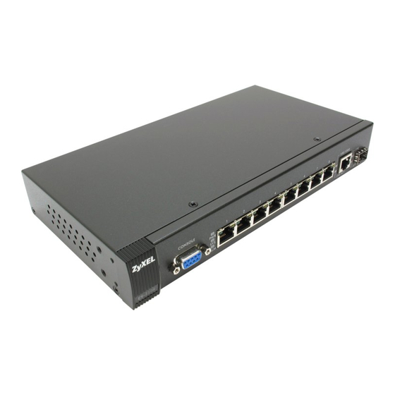
This chapter describes the front panel and rear panel of the switch and shows you how to make the hardware connections. 3.1 Front Panel Connection The figure below shows the front panel of the switch. Figure 9 Front Panel: ES-2108 Figure 10 Front Panel: ES-2108-G/ES-2108PWR Console Port Figure 11 Front Panel: ES-2108-LC... -
Page 38: Console Port
Alternatively, use a mini-GBIC transceiver in this slot for fiber-optical connections to backbone Ethernet switches. 100 Base-FX This is a 100-Base FX fiber-optic module and is only available on the ES-2108-LC. Fiber-Optic Use the fiber optic cable to connect this uplink port to a backbone Ethernet switche. -
Page 39: Default Ethernet Settings
Figure 12 Transceiver Installation Example 2 Press the transceiver firmly until it clicks into place. 3 The switch automatically detects the installed transceiver. Check the LEDs to verify that it is functioning properly. Chapter 3 Hardware Overview ES-2108 Series User’s Guide... -
Page 40: Transceiver Removal
Figure 15 Transceiver Removal Example 3.1.4 100 Base-FX Fiber-Optic Port This 100 Base-FX fiber-optic port is only available on the ES-2108-LC. Note: To avoid possible eye injury, do not look directly into a module’s fiber-optic connectors. Keep the dust cover on a fiber-optic module until you connect it. -
Page 41: Rear Panel
The link to a 10 Mbps Ethernet network is up. Blinking The system is transmitting/receiving to/from a 100 Mbps Ethernet network. The link to a 100 Mbps Ethernet network is up. The link to an Ethernet network is down. ES-2108 Series User’s Guide... - Page 42 ES-2108 Series User’s Guide Table 2 Front Panel LEDs (continued) COLOR 1 - 8 Green (Ethernet ports) (ES- 2108PWR only) Amber 100/1000 Green Amber LNK/ACT Green LNK (mini- Green GBIC Slot) ACT (mini Green GBIC Slot) LNK (100 Green ACT (100...
-
Page 43: The Web Configurator
1234. The date and time display as shown if you have not configured a time server nor manually entered a time and date in the General Setup screen. Chapter 4 The Web Configurator H A P T E R The Web Configurator [ENTER] ES-2108 Series User’s Guide... -
Page 44: The Status Screen
ES-2108 Series User’s Guide Figure 17 Web Configurator: Login 4 Click OK to view the first web configurator screen. 4.3 The Status Screen The Status screen is the first screen that displays when you access the web configurator. The following figure shows the navigating components of a web configurator screen. -
Page 45: Table 3 Navigation Panel Sub-Links Overview
In the navigation panel, click a main link to reveal a list of submenu links. Table 3 Navigation Panel Sub-links Overview ADVANCED BASIC SETTING APPLICATION Chapter 4 The Web Configurator ES-2108 Series User’s Guide IP APPLICATION MANAGEMENT... -
Page 46: Table 4 Web Configurator Screen Sub-Links Details
ES-2108 Series User’s Guide The following table lists the various web configurator screens within the sub-links. Table 4 Web Configurator Screen Sub-links Details BASIC SETTING System Info General Setup Switch Setup IP Setup Port Setup The following table describes the links in the navigation panel. - Page 47 This link takes you to a screen where you can view the MAC addresses (and types) of devices attached to what ports and VLAN IDs. ARP Table This link takes you to a screen where you can view the MAC addresses – IP address resolution table. Chapter 4 The Web Configurator ES-2108 Series User’s Guide...
-
Page 48: Change Your Password
ES-2108 Series User’s Guide 4.3.1 Change Your Password After you log in for the first time, it is recommended you change the default administrator password. Click Management, Access Control and then Logins to display the next screen. Figure 19 Change Administrator Login Password 4.4 Switch Lockout... -
Page 49: Resetting The Switch
The switch is now re initialized with the factory-default configuration file including the default password of “1234”. Chapter 4 The Web Configurator for details. Press any key to enter Debug Mode within 3 ” message. Enter Debug Mode ” message before activating XMODEM ES-2108 Series User’s Guide to restart the switch. atgo... -
Page 50: Logging Out Of The Web Configurator
ES-2108 Series User’s Guide 4.6 Logging Out of the Web Configurator Click Logout in a screen to exit the web configurator. You have to log in with your password again after you log out. This is recommended after you finish a management session both for security reasons and so as you don’t lock out other switch administrators. -
Page 51: Initial Setup Example
In this example, you want to configure port 5 as a member of VLAN 2. Figure 22 Initial Setup Network Example: VLAN Chapter 5 Initial Setup Example H A P T E R Initial Setup Example ES-2108 Series User’s Guide... -
Page 52: Setting Port Vid
ES-2108 Series User’s Guide 1 Click Advanced Application and VLAN in the navigation panel and click the Static VLAN link. 2 In the Static VLAN screen, select ACTIVE, enter a descriptive name in the Name field and enter 2 in the VLAN Group ID field for the VLAN2 network. -
Page 53: Configuring Switch Management Ip Address
The default management IP address of the switch is 192.168.1.1. You can configure another IP address in a different subnet for management purposes. The following figure shows an example. Figure 24 Initial Setup Example: Management IP Address Chapter 5 Initial Setup Example ES-2108 Series User’s Guide... - Page 54 ES-2108 Series User’s Guide 1 Connect your computer to any Ethernet port on the switch. Make sure your computer is in the same subnet as the switch. 2 Open your web browser and enter 192.168.1.1 (the default IP address) in the address bar to access the web configurator.
-
Page 55: System Status And Port Statistics
To view the port statistics, click Status in all web configurator screens to display the Status screen as shown next. Figure 25 Status (ES-2108PWR) Chapter 6 System Status and Port Statistics ES-2108 Series User’s Guide H A P T E R Statistics... -
Page 56: Status: Port Details
ES-2108 Series User’s Guide The following table describes the labels in this screen. Table 6 Status LABEL DESCRIPTION System up Time This field shows how long the system has been running since the last time it was started. Port This identifies the Ethernet port. Click a port number to display the Port Details... -
Page 57: Figure 26 Status: Port Details (Es-2108Pwr)
The switch can provide up to 351.36mA current to one PD connected to each 10/ 100Mbps Ethernet port and up to a total of 123.2W power to all PDs connected to the switch. Chapter 6 System Status and Port Statistics ES-2108 Series User’s Guide... - Page 58 ES-2108 Series User’s Guide Table 7 Status: Port Details (continued) LABEL DESCRIPTION This field is only available on the ES-2108PWR but not available for the Gigabit and Consumption mini-GBIC ports. This field shows the power consumption of the powered device connected to the port.
- Page 59 Poll Interval(s) The text box displays how often (in seconds) this screen refreshes. You may change the refresh interval by typing a new number in the text box and then clicking Set Interval. Stop Click Stop to stop port statistic polling. Chapter 6 System Status and Port Statistics ES-2108 Series User’s Guide...
- Page 60 ES-2108 Series User’s Guide Chapter 6 System Status and Port Statistics...
-
Page 61: Chapter 7 Basic Setting
In the navigation panel, click Basic Setting and System Info to display the screen as shown. You can check the firmware version number and monitor the switch temperature, fan speeds and voltage (on the ES-2108PWR) in this screen. Chapter 7 Basic Setting ES-2108 Series User’s Guide H A P T E R Basic Setting... -
Page 62: Figure 27 System Info (Es-2108Pwr)
ES-2108 Series User’s Guide Figure 27 System Info (ES-2108PWR) The following table describes the labels in this screen. Table 8 System Info LABEL DESCRIPTION System Name This field displays the descriptive name of the switch for identification purposes. ZyNOS F/W... -
Page 63: General Setup
Set Interval. Stop Click Stop to halt statistic polling. 7.3 General Setup Click Basic Setting and General Setup in the navigation panel to display the screen as shown. Chapter 7 Basic Setting ES-2108 Series User’s Guide... -
Page 64: Figure 28 General Setup
ES-2108 Series User’s Guide Figure 28 General Setup The following table describes the labels in this screen. Table 9 General Setup LABEL DESCRIPTION System Name Choose a descriptive name for identification purposes. This name consists of up to 32 printable characters; spaces are allowed. -
Page 65: Introduction To Vlans
In traditional switched environments, all broadcast packets go to each and every individual port. With VLAN, all broadcasts are confined to a specific broadcast domain. Note: VLAN is unidirectional; it only governs outgoing traffic. Chapter 7 Basic Setting ES-2108 Series User’s Guide... -
Page 66: Igmp Snooping
ES-2108 Series User’s Guide Chapter 8 on page 73 7.5 IGMP Snooping A switch can passively snoop on IGMP Query, Report and Leave (IGMP version 2) packets transferred between IP multicast routers/switches and IP multicast hosts to learn the IP multicast group membership. -
Page 67: Table 10 Switch Setup
Level 0 Typically used for best-effort traffic. Chapter 7 Basic Setting Chapter 8 on page 73 for more information. Section 7.5 on page 66 ES-2108 Series User’s Guide for more information on IGMP snooping. -
Page 68: Ip Setup
ES-2108 Series User’s Guide Table 10 Switch Setup (continued) LABEL DESCRIPTION Apply Click Apply to save the settings. Cancel Click Cancel to reset the fields to your previous configuration. 7.7 IP Setup Use the IP Setup screen to configure the default gateway device, the default domain name server and add switch IP address. -
Page 69: Table 11 Ip Setup
Subnet Mask This field displays the subnet mask of the switch. This field displays the VLAN identification number of the network. Delete Click Delete to remove the selected entry from the summary table. Cancel Click Cancel to clear the Delete check boxes. Chapter 7 Basic Setting ES-2108 Series User’s Guide... -
Page 70: Port Setup
For the Gigabit Ethernet/mini-GBIC port, select Auto, 10M/Half Duplex, 10M/Full Duplex, 100M/Half Duplex, 100M/Full Duplex or 1000M/Full Duplex. For the mini-GBIC port on the ES-2108-LC, select Auto or 1000M/Full Duplex. The port speed and the duplex mode are fixed (100M/Full Duplex) for the 100 Base- FX fiber optic port on the ES-2108-LC. - Page 71 Select the check box to allow a powered device (connected to the port) to receive power from the switch. Apply Click Apply to save the settings. Cancel Click Cancel to reset the fields to your previous configuration. Chapter 7 Basic Setting ES-2108 Series User’s Guide Table 10 on page 67 for more information.
- Page 72 ES-2108 Series User’s Guide Chapter 7 Basic Setting...
-
Page 73: Chapter 8 Vlan
VLAN tag reflecting the ingress port's default VID. The default PVID is VLAN 1 for all ports, but this can be changed. Chapter 8 VLAN H A P T E R VLAN ID 1 Bit 12 bits ES-2108 Series User’s Guide VLAN... -
Page 74: Automatic Vlan Registration
ES-2108 Series User’s Guide 8.2 Automatic VLAN Registration GARP and GVRP are the protocols used to automatically register VLAN membership across switches. 8.2.1 GARP GARP (Generic Attribute Registration Protocol) allows network switches to register and de- register attribute values with other GARP participants within a bridged LAN. GARP is a protocol that provides a generic mechanism for protocols that serve a more specific application, for example, GVRP. -
Page 75: Port Vlan Trunking
You may choose to accept both tagged and untagged type incoming frames or just tagged incoming frames on a port. Ingress filtering If set, the switch discards incoming frames for VLANs that do not have this port as a member ES-2108 Series User’s Guide... -
Page 76: Static Vlan
ES-2108 Series User’s Guide 8.5 Static VLAN Use a static VLAN to decide whether an incoming frame on a port should be • sent to a VLAN group as normal depends on its VLAN tag. • sent to a group whether it has a VLAN tag or not. -
Page 77: Configure A Static Vlan
Enter a descriptive name for the VLAN group for identification purposes. VLAN Group ID Enter the VLAN ID for this static entry; the valid range is between 1 and 4094. Port The port number identifies the port you are configuring. Chapter 8 VLAN ES-2108 Series User’s Guide... -
Page 78: Configure Vlan Port Settings
ES-2108 Series User’s Guide Table 15 VLAN: Static VLAN (continued) LABEL DESCRIPTION Control Select Normal for the port to dynamically join this VLAN group using GVRP. This is the default selection. Select Fixed for the port to be a permanent member of this VLAN group. -
Page 79: Port-Based Vlan Setup
In screens (such as IP Setup and Filtering) that require a VID, you must enter 1 as the VID. The port-based VLAN setup screen is shown next. The CPU management port forms a VLAN with all Ethernet ports. Chapter 8 VLAN ES-2108 Series User’s Guide... -
Page 80: Configure A Port-Based Vlan
ES-2108 Series User’s Guide 8.6.1 Configure a Port-based VLAN Select Port Based as the VLAN Type in the Switch Setup screen (see and then click VLAN from the navigation panel to display the next screen. Figure 37 Port Based VLAN Setup (All Connected) -
Page 81: Figure 38 Port Based Vlan Setup (Port Isolation)
CPU refers to the switch management port. By default it forms a VLAN with all Ethernet ports. If it does not form a VLAN with a particular port then the switch cannot be managed from that port. Chapter 8 VLAN ES-2108 Series User’s Guide... - Page 82 ES-2108 Series User’s Guide Table 17 Port Based VLAN Setup (continued) LABEL DESCRIPTION Apply Click Apply to save the changes. Cancel Click Cancel to start configuring the screen again. Chapter 8 VLAN...
-
Page 83: Static Mac Forwarding
Click Advanced Applications, Static MAC Forwarding in the navigation panel to display the configuration screen as shown. Figure 39 Static MAC Forwarding Chapter 9 Static MAC Forwarding ES-2108 Series User’s Guide H A P T E R Chapter 17 on page 107 for more information... -
Page 84: Table 18 Static Mac Forwarding
ES-2108 Series User’s Guide The following table describes the labels in this screen. Table 18 Static MAC Forwarding LABEL DESCRIPTION Active Select this check box to activate your rule. You may temporarily deactivate a rule without deleting it by clearing this check box. -
Page 85: Chapter 10 Filtering
Type a descriptive name (up to 32 printable ASCII characters) for this rule. This is for identification purpose only. Type a MAC address in valid MAC address format, that is, six hexadecimal character pairs. Type the VLAN group identification number. Chapter 10 Filtering ES-2108 Series User’s Guide H A P T E R Filtering... - Page 86 ES-2108 Series User’s Guide Table 19 FIltering (continued) LABEL DESCRIPTION Click Add to save the new rule to the switch. It then displays in the summary table at the bottom of the screen. Cancel Click Cancel to reset the fields to your previous configuration.
-
Page 87: Chapter 11 Spanning Tree Protocol
RANGE 100 to 1000 50 to 600 40 to 400 10 to 60 3 to 10 1 to 5 ES-2108 Series User’s Guide ALLOWED RANGE 1 to 65535 1 to 65535 1 to 65535 1 to 65535 1 to 65535... -
Page 88: How Stp Works
ES-2108 Series User’s Guide 11.1.2 How STP Works After a bridge determines the lowest cost-spanning tree with STP, it enables the root port and the ports that are the designated ports for connected LANs, and disables all other ports that participate in STP. -
Page 89: Figure 41 Spanning Tree Protocol: Status
This is the number of times the spanning tree has been reconfigured. Times Time Since Last This is the time since the spanning tree was last reconfigured. Change Chapter 11 Spanning Tree Protocol ES-2108 Series User’s Guide Section 11.3 on page... -
Page 90: Configure Stp
ES-2108 Series User’s Guide Table 22 Spanning Tree Protocol: Status (continued) LABEL DESCRIPTION Polling Interval The text box displays how often (in seconds) this screen refreshes. You may change the refresh interval by typing a new number in the text box and then clicking Set Interval. - Page 91 - see Apply Click Apply to save your changes back to the switch. Cancel Click Cancel to begin configuring this screen afresh. Chapter 11 Spanning Tree Protocol ES-2108 Series User’s Guide Table 20 on page 87 for more information.
- Page 92 ES-2108 Series User’s Guide Chapter 11 Spanning Tree Protocol...
-
Page 93: Chapter 12 Bandwidth Control
Select this check box to enable bandwidth control on the switch. Port This field displays the port number. Active Make sure to select this check box to activate bandwidth control on a port. Chapter 12 Bandwidth Control ES-2108 Series User’s Guide H A P T E R Bandwidth Control... - Page 94 ES-2108 Series User’s Guide Table 24 Bandwidth Control (continued) LABEL DESCRIPTION Ingress Rate Specify the maximum bandwidth allowed in Kilobits per second (Kbps) for the incoming traffic flow on a port. If you enter a number between 64 and 1728, the switch automatically rounds the number down to the nearest multiple of 64.
-
Page 95: Broadcast Storm Control
Select this check box to enable broadcast storm control on the switch. Clear this check box to disable the feature. Port This field displays a port number. Chapter 13 Broadcast Storm Control ES-2108 Series User’s Guide H A P T E R... - Page 96 ES-2108 Series User’s Guide Table 25 Broadcast Storm Control (continued) LABEL DESCRIPTION Active Select this check box to enable broadcast storm control on the port. Clear this check box to disable the feature. Rate Specify the traffic a port receives in Kilobits per second (Kbps).
-
Page 97: Chapter 14 Mirroring
Click Advanced Application, Mirroring in the navigation panel to display the Mirroring screen. Use this screen to select a mirror port and specify the traffic flow to be copied to the mirror port. Figure 45 Mirroring Chapter 14 Mirroring ES-2108 Series User’s Guide H A P T E R Mirroring... -
Page 98: Table 26 Mirroring
ES-2108 Series User’s Guide The following table describes the labels in this screen. Table 26 Mirroring LABEL DESCRIPTION Active Clear this check box to deactivate port mirroring on the switch. Mirror Port The mirror port is the port you copy the traffic to in order to examine it in more detail without interfering with the traffic flow on the original port(s). -
Page 99: Chapter 15 Link Aggregation
• All ports in the same trunk group must have the same media type, speed, duplex mode and flow control settings. Configure trunk groups or LACP before you connect the Ethernet switch to avoid causing network topology loops. Chapter 15 Link Aggregation ES-2108 Series User’s Guide H A P T E R Link Aggregation... -
Page 100: Link Aggregation Id
ES-2108 Series User’s Guide 15.2.1 Link Aggregation ID LACP aggregation ID consists of the following information Table 27 Link Aggregation ID: Local Switch SYSTEM PRIORITY MAC ADDRESS 0000 Table 28 Link Aggregation ID: Peer Switch SYSTEM PRIORITY MAC ADDRESS 0000 15.3 Link Aggregation Status... -
Page 101: Link Aggregation Setup
Click Configuration in the Link Aggregation Control Protocol Status screen to display the screen shown next. Figure 47 Link Aggregation: Configuration Chapter 15 Link Aggregation Section 15.2.1 on page 100 for more information on this field. ES-2108 Series User’s Guide... -
Page 102: Table 30 Link Aggregation Control Protocol: Configuration
ES-2108 Series User’s Guide The following table describes the labels in this screen. Table 30 Link Aggregation Control Protocol: Configuration LABEL DESCRIPTION Link Aggregation Control Protocol Active Select this checkbox to enable Link Aggregation Control Protocol (LACP). System LACP system priority is a number between 1 and 65,535. The switch with the lowest... -
Page 103: Chapter 16 Port Authentication
Windows operating system support. For other operating systems, see its documentation. If your operating system does not support 802.1x, then you may need to install 802.1x client software. Chapter 16 Port Authentication H A P T E R Port Authentication that allows support of RADIUS (Remote ES-2108 Series User’s Guide... -
Page 104: Activate Ieee 802.1X Security
ES-2108 Series User’s Guide Figure 49 Port Authentication 16.2.1 Activate IEEE 802.1x Security From the Port Authentication screen, display the configuration screen as shown. Figure 50 Port Authentication: 802.1x The following table describes the labels in this screen. Table 31 Port Authentication: 802.1x... -
Page 105: Configuring Radius Server Settings
This key must be the same on the external RADIUS server and the switch. Apply Click Apply to save your changes back to the switch. Cancel Click Cancel to begin configuring this screen afresh. Chapter 16 Port Authentication ES-2108 Series User’s Guide... - Page 106 ES-2108 Series User’s Guide Chapter 16 Port Authentication...
-
Page 107: Chapter 17 Port Security
MAC address learning as this will result in many broadcasts. 17.2 Port Security Setup Click Advanced Application, Port Security in the navigation panel to display the screen as shown. Figure 52 Port Security Chapter 17 Port Security ES-2108 Series User’s Guide H A P T E R Port Security... -
Page 108: Table 33 Port Security
ES-2108 Series User’s Guide The following table describes the labels in this screen. Table 33 Port Security LABEL DESCRIPTION Active Select this check box to enable the port security feature on the switch. Port This field displays a port number. -
Page 109: Chapter 18 Queuing Method
This works in a looping fashion until a queue is empty. Chapter 18 Queuing Method ES-2108 Series User’s Guide H A P T E R Queuing Method... -
Page 110: Configuring Queuing Method
ES-2108 Series User’s Guide Weighted Round Robin Scheduling (WRR) uses the same algorithm as round robin scheduling, but services queues based on their priority and queue weight (the number you configure in the queue Weight field) rather than a fixed amount of bandwidth. WRR is activated only when a port has more traffic than it can handle. -
Page 111: Chapter 19 Static Route
Enter the IP address of the gateway. The gateway is an immediate neighbor of your Address switch that will forward the packet to the destination. The gateway must be a router on the same segment as your switch. Chapter 19 Static Route ES-2108 Series User’s Guide H A P T E R Static Route... - Page 112 ES-2108 Series User’s Guide Table 36 Static Routing (continued) LABEL DESCRIPTION Metric The metric represents the “cost” of transmission for routing purposes. IP routing uses hop count as the measurement of cost, with a minimum of 1 for directly connected networks.
-
Page 113: Differentiated Services
DSCP values and the configured policies. 20.1.2 DiffServ Network Example The following figure depicts a simple DiffServ network consisting of a group of contiguous DiffServ-compliant network devices. Chapter 20 Differentiated Services ES-2108 Series User’s Guide H A P T E R DS (2 bits) -
Page 114: Activating Diffserv
ES-2108 Series User’s Guide Figure 56 DiffServ Network Example Switch A marks traffic flowing into the network based on the configured marking rules. Intermediary network devices 1 and 2 allocate network resources (such as bandwidth) by mapping the DSCP values and the associated policies. -
Page 115: Dscp-To-Ieee802.1P Priority Mapping
Click Cancel to discard all changes and start configuring the screen again. Chapter 20 Differentiated Services 8 – 15 16 – 23 24 – 31 32 – 39 ES-2108 Series User’s Guide 40 – 47 48 – 55 56 – 63... - Page 116 ES-2108 Series User’s Guide Chapter 20 Differentiated Services...
-
Page 117: Chapter 21 Maintenance
If you want to access the switch web configurator again, you may need to change the IP address of your computer to be in the same subnet as that of the default switch IP address (192.168.1.1). rebooting). This does not affect the switch's configuration. ES-2108 Series User’s Guide... -
Page 118: Firmware Upgrade
ES-2108 Series User’s Guide 21.2 Firmware Upgrade Make sure you have downloaded (and unzipped) the correct model firmware and version to your computer before uploading to the device. Note: Be sure to upload the correct model firmware as uploading the wrong model firmware may damage your device. -
Page 119: Backing Up A Configuration File
The following message appears. Figure 63 Load Factory Default: Conformation 2 Click OK to display the screen shown next. Chapter 21 Maintenance ES-2108 Series User’s Guide... -
Page 120: Reboot System
ES-2108 Series User’s Guide Figure 64 Load Factory Default: Start 3 Click OK to begin resetting all switch configurations to the factory defaults and then wait for the switch to restart. This takes up to two minutes. If you want to access the switch web configurator again, you may need to change the IP address of your computer to be in the same subnet as that of the default switch IP address (192.168.1.1). -
Page 121: Example Ftp Commands
This is the generic name for the ZyNOS firmware on the switch. transfers the firmware on your computer (firmware.bin) to the put config.cfg config transfers the configuration file on the switch to Table 41 on page 121 ES-2108 Series User’s Guide transfers the for more... -
Page 122: Gui-Based Ftp Clients
ES-2108 Series User’s Guide 7 Enter to exit the ftp prompt. quit 21.7.3 GUI-based FTP Clients The following table describes some of the commands that you may see in GUI-based FTP clients. General Commands for GUI-based FTP Clients COMMAND Host Address... -
Page 123: Chapter 22 Access Control
22.2 The Access Control Main Screen Click Management, Access Control in the navigation panel to display the main screen as shown. Figure 68 Access Control Chapter 22 Access Control ES-2108 Series User’s Guide H A P T E R Access Control Telnet SNMP... -
Page 124: About Snmp
ES-2108 Series User’s Guide 22.3 About SNMP Simple Network Management Protocol (SNMP) is an application layer protocol used to manage and monitor TCP/IP-based devices. SNMP is used to exchange management information between the network management system (NMS) and a network element (NE). A manager station can manage and monitor the switch through the network via SNMP version one (SNMPv1) and/or SNMP version 2c. -
Page 125: Supported Mibs
This trap is sent when the switch restarts. This trap is sent when the Ethernet link is down. This trap is sent when the Ethernet link is up. This trap is sent when an SNMP request comes from non-authenticated hosts. ES-2108 Series User’s Guide... -
Page 126: Setting Up Login Accounts
ES-2108 Series User’s Guide Figure 70 Access Control: SNMP The following table describes the labels in this screen. Table 45 Access Control: SNMP LABEL DESCRIPTION Get Community Enter the get community, which is the password for the incoming Get- and GetNext- requests from the management station. -
Page 127: Ssh Overview
Enter your new system password. Set a user name (up to 30 characters long). Enter your new system password. Click Apply to save your changes back to the switch. Click Cancel to begin configuring this screen afresh. ES-2108 Series User’s Guide... -
Page 128: How Ssh Works
ES-2108 Series User’s Guide Figure 72 SSH Communication Example 22.6 How SSH works The following table summarizes how a secure connection is established between two remote hosts. Figure 73 How SSH Works 1 Host Identification The SSH client sends a connection request to the SSH server. The server identifies itself with a host key. -
Page 129: Ssh Implementation On The Switch
You can use an SSH client program to access the switch. The following figure shows an example using a text-based SSH client program. Refer to the documentation that comes with your SSH program for information on using it. Chapter 22 Access Control ES-2108 Series User’s Guide... -
Page 130: Introduction To Https
SSH/hostkeys/key_22_192.168.1.1.pub host key for 192.168.1.1, accepted by Administrator Thu May 12 2005 09:52:21 admin's password: Authentication successful. Copyright (c) 1994 - 2005 ZyXEL Communications Corp. ras> 22.8 Introduction to HTTPS HTTPS (Hyper Text Transfer Protocol over Secure Socket Layer, or HTTP over SSL) is a web protocol that encrypts and decrypts web pages. -
Page 131: Https Example
You see the following Security Alert screen in Internet Explorer. Select Yes to proceed to the web configurator login screen; if you select No, then web configurator access is blocked. Chapter 22 Access Control ES-2108 Series User’s Guide... -
Page 132: Netscape Navigator Warning Messages
ES-2108 Series User’s Guide Figure 76 Security Alert Dialog Box (Internet Explorer) 22.9.2 Netscape Navigator Warning Messages When you attempt to access the switch HTTPS server, a Website Certified by an Unknown Authority screen pops up asking if you trust the server certificate. Click Examine Certificate if you want to verify that the certificate is from the switch. -
Page 133: The Main Screen
After you accept the certificate and enter the login username and password, the switch main screen appears. The lock displayed in the bottom right of the browser status bar denotes a secure connection. Chapter 22 Access Control ES-2108 Series User’s Guide... -
Page 134: Service Port Access Control
ES-2108 Series User’s Guide Figure 79 Login Screen (Internet Explorer) Figure 80 Login Screen (Netscape) 22.10 Service Port Access Control Service Access Control allows you to decide what services you may use to access the switch. You may also change the default service port and configure “trusted computer(s)” for each service in the Remote Management screen (discussed later). -
Page 135: Remote Management
You can specify a group of one or more “trusted computers” from which an administrator may use a service to manage the switch. Click Access Control to return to the Access Control screen. Chapter 22 Access Control ES-2108 Series User’s Guide... -
Page 136: Figure 82 Access Control: Remote Management
ES-2108 Series User’s Guide Figure 82 Access Control: Remote Management The following table describes the labels in this screen. Table 48 Access Control: Remote Management LABEL DESCRIPTION Entry This is the client set index number. A “client set” is a group of one or more “trusted computers”... -
Page 137: Chapter 23 Diagnostic
Click Ping to have the switch ping the IP address (in the field to the left). Ethernet Port Test From the Port drop-down list box, select a port number and click Port Test to perform internal loopback test. Chapter 23 Diagnostic ES-2108 Series User’s Guide H A P T E R Diagnostic... - Page 138 ES-2108 Series User’s Guide Chapter 23 Diagnostic...
-
Page 139: Chapter 24 Cluster Management
Chapter 24 Cluster Management H A P T E R Cluster Management Must be compatible with ZyXEL cluster management implementation. The switch through which you manage the cluster member switches. The switches being managed by the cluster manager switch. ES-2108 Series User’s Guide... -
Page 140: Cluster Management Status
ES-2108 Series User’s Guide 24.2 Cluster Management Status Click Management, Cluster Management in the navigation panel to display the following screen. Note: A cluster can only have one manager. Figure 85 Cluster Management: Status The following table describes the labels in this screen. -
Page 141: Cluster Member Switch Management
Figure 86 Cluster Management: Cluster Member Web Configurator Screen 24.2.1.1 Uploading Firmware to a Cluster Member Switch You can use FTP to upload firmware to a cluster member switch through the cluster manager switch as shown in the following example. Chapter 24 Cluster Management ES-2108 Series User’s Guide... -
Page 142: Configuring Cluster Management
ES-2108 Series User’s Guide Figure 87 Example: Uploading Firmware to a Cluster Member Switch C:\>ftp 192.168.1.1 Connected to 192.168.1.1. FTP version 1.0 ready at Thu Jan User (192.168.1.1:(none)): admin 331 Enter PASS command Password: 230 Logged in ftp> ls 200 Port command okay... -
Page 143: Figure 88 Clustering Management Configuration
Clustering Candidate list. Switches that are not in the same management VLAN group will not be visible in the Clustering Candidate list. ES-2108 Series User’s Guide ) appears in the member summary list... - Page 144 ES-2108 Series User’s Guide Table 53 Clustering Management Configuration (continued) LABEL Password Cancel Refresh The next summary table shows the information for the clustering members configured. Index HwAddr Name Model Remove Cancel DESCRIPTION Each cluster member’s password is its web configurator password. Select a member in the Clustering Candidate list and then enter its web configurator password.
-
Page 145: Chapter 25 Mac Table
Too much port flooding leads to network congestion. If the switch has already learned the port for this MAC address, but the destination port is the same as the port it came in on, then it filters the frame. ES-2108 Series User’s Guide MAC Table... -
Page 146: Viewing The Mac Table
ES-2108 Series User’s Guide 25.2 Viewing the MAC Table Click Management, MAC Table in the navigation panel to display the following screen. Figure 90 MAC Table The following table describes the labels in this screen. Table 54 MAC Table LABEL... -
Page 147: Chapter 26 Arp Table
26.2 Viewing the ARP Table Click Management, ARP Table in the navigation panel to open the following screen. Use the ARP table to view IP-to-MAC address mapping(s). Chapter 26 ARP Table ES-2108 Series User’s Guide H A P T E R ARP Table... -
Page 148: Figure 91 Arp Table
ES-2108 Series User’s Guide Figure 91 ARP Table The following table describes the labels in this screen. Table 55 ARP Table LABEL DESCRIPTION Index This is the ARP Table entry number. IP Address This is the learned IP address of a device connected to a switch port with corresponding MAC address below. -
Page 149: Introducing The Commands
Note: The switch automatically logs you out of the management interface after five minutes of inactivity. If this happens to you, simply log back in again. Chapter 27 Introducing the Commands ES-2108 Series User’s Guide H A P T E R... -
Page 150: Access Priority
You can view the initialization information using the console port. After the initialization, the login screen displays (refer to Figure 92 Initial Console Port Screen Copyright (c) 1994 - 2004 ZyXEL Communications Corp. initialize switch, ethernet address: 00:13:49:1a:d4:fa ZyXEL ADM5120 10/100 Mbps Ethernet Controller 2002.9.27.0 Press ENTER to continue... -
Page 151: Ssh
SSH/hostkeys/key_22_192.168.1.1.pub host key for 192.168.1.1, accepted by Administrator Thu May 12 2005 09:52:21 admin's password: Authentication successful. Copyright (c) 1994 - 2005 ZyXEL Communications Corp. ras> 27.3 The Login Screen After you have successfully established a connection to the switch using a direct console connection or Telnet, a login screen displays as shown below. -
Page 152: Command Syntax Conventions
ES-2108 Series User’s Guide 27.4 Command Syntax Conventions The rules of the commands are listed next. • The command keywords are in • The required fields in a command are enclosed in angle brackets <>, for instance, means that you must specify an IP number for this command. -
Page 153: Detailed Command Information
Show a list of previously run commands Exit from the EXEC Exec ping Show system information SSH client Exec traceroute to display detailed sub command and parameters. to display detailed help information about the sub commands and ES-2108 Series User’s Guide... -
Page 154: Command Modes
ES-2108 Series User’s Guide Figure 97 CLI Help: Detailed Command Information: Example 1 ras> ping help Commands available: ping <ip> < [ vlan <vlan-id> ] [ size <0-1472> ] [ -t ] > ras> Figure 98 CLI: Help: Detailed Command Information: Example 2 ras>... -
Page 155: Using Command History
CLI. See the related section in the User’s Guide for more background information. Chapter 27 Introducing the Commands command is not available in User mode. command to log out of the CLI. exit logout ES-2108 Series User’s Guide . Use the history command [ENTER] write memory... -
Page 156: User Mode
ES-2108 Series User’s Guide 27.9.1 User Mode The following table describes the commands available for User mode. Table 56 Command Summary: User Mode COMMAND enable exit help history logout ping <IP|host-name> <IP|host-name> [vlan <vlan-id>] [size <0-1472>] [-t] help show system-information <1|2>... -
Page 157: Show Cluster
<port- number> interfaces config <port-list> Chapter 27 Introducing the Commands ES-2108 Series User’s Guide DESCRIPTION Accesses Enable (or privileged) mode. Resets to the factory default settings. Exits Enable (or privileged) mode. Displays help information. Displays a list of command(s) that you have previously executed. - Page 158 ES-2108 Series User’s Guide Table 57 Command Summary: Enable Mode (continued) COMMAND lacp logging loginPrecedence logins mac-aging-time multi-login port-access- authenticator port-security radius-server remote-management running-config service-control snmp-server spanning-tree DESCRIPTION Displays broadcast storm control settings. bstorm-control Displays outgoing port information. egress Displays IP related information.
-
Page 159: General Configuration Mode
<confirm-string> bandwidth- control diffserv dscp <0-63> priority <0-7> Chapter 27 Introducing the Commands ES-2108 Series User’s Guide DESCRIPTION Displays current SSH session(s). session Displays general system information. Displays current system time and date. Displays time server information. Displays link aggregation information. - Page 160 ES-2108 Series User’s Guide Table 58 Command Summary: Configuration Mode (continued) COMMAND exit garp join <100-65535> leave <msec> leaveall <msec> help history hostname <name_string> https cert-regeneration <rsa|dsa> timeout <0-65535> igmp-snooping interface port-channel <port- list> name-server route lacp system-priority loginPrecedence <LocalOnly | LocalRADIUS | RADIUSOnly>...
-
Page 161: Cluster Member
Chapter 27 Introducing the Commands ES-2108 Series User’s Guide DESCRIPTION Configures a static MAC address forwarding rule. Disables a static MAC address inactive forwarding rule. Sets port mirroring for the MAC mac <mac-addr>... - Page 162 ES-2108 Series User’s Guide Table 58 Command Summary: Configuration Mode (continued) COMMAND mac-filter mac-forward mirror-port multi-login port-access- authenticator port-security radius-server remote-management service-control DESCRIPTION Enables the specified MAC-filter mac <mac-addr> rule. vlan <vlan-id> drop <src/dst/ both> inactive Disables the specified MAC mac <mac-addr>...
- Page 163 Chapter 27 Introducing the Commands ES-2108 Series User’s Guide DESCRIPTION Disables secure web browser https access to the switch. Disables ICMP access to the icmp switch such as pinging and tracerouting. Disables SNMP management.
- Page 164 ES-2108 Series User’s Guide Table 58 Command Summary: Configuration Mode (continued) COMMAND <port-list> port-security <port-list> queue level <0-7> priority <0-3> radius-server host <ip> [acct- port <socket- number>] [key <key- string>] remote- <index> start-addr management <ip> end-addr <ip> service [telnet][ftp][http ][icmp][snmp][ssh] [https] service-control ftp <socket-number>...
- Page 165 <ip> trunk <T1|T2> <T1|T2>interface <port-list> Chapter 27 Introducing the Commands ES-2108 Series User’s Guide DESCRIPTION Sets the get community. Sets the set community. Sets the trap community. Sets the IP addresses of up to four stations to send your SNMP traps to.
-
Page 166: Interface Port-Channel Commands
ES-2108 Series User’s Guide Table 58 Command Summary: Configuration Mode (continued) COMMAND <T1|T2>lacp interface <port- list> timeout <lacp-timeout> vlan <1-4094> vlan-type <802.1q|port-based> vlan1q gvrp ingress-check port-isolation 27.9.4 interface port-channel Commands The following table lists the Use these commands to configure the ports. - Page 167 <port-name- string> Chapter 27 Introducing the Commands ES-2108 Series User’s Guide DESCRIPTION Exits from the interface port- channel command mode. Enables interface flow control. Flow control regulates transmissions to match the bandwidth of the receiving port.
-
Page 168: Config-Vlan Commands
ES-2108 Series User’s Guide Table 59 interface port-channel Commands (continued) COMMAND pvid <1-4094> qos priority speed-duplex test vlan-trunking 27.9.5 config-vlan Commands The following table lists the Table 60 Command Summary: config-vlan Commands COMMAND vlan <1-4094> exit fixed <port-list> forbidden <port- list>... - Page 169 Table 60 Command Summary: config-vlan Commands (continued) COMMAND name <name-str> normal <port- list> untagged <port- list> Chapter 27 Introducing the Commands ES-2108 Series User’s Guide DESCRIPTION Sets a default gateway IP address for default-gateway this VLAN. <ip-address> Sets the dynamic in-band IP address default-...
- Page 170 ES-2108 Series User’s Guide Chapter 27 Introducing the Commands...
-
Page 171: Chapter 28 Command Examples
System up Time Bootbase Version ras> Chapter 28 Command Examples H A P T E R Command Examples commands. show : ES-2108 : 00:13:49:1a:d4:fa : V3.60(TX.0)| 04/22/2005 : 1816320 0:59:37 (5757d ticks) : V1.07 | 04/20/2005 ES-2108 Series User’s Guide... -
Page 172: Show Ip
ES-2108 Series User’s Guide 28.2.2 show ip Syntax: show ip This command displays the IP related information (such as IP address and subnet mask) on all switch interfaces. The following figure shows the default interface settings. Figure 102 show ip Command Example ras>... -
Page 173: Show Interface
This command displays statistics of a port. The following example shows that port 2 is up and the related information. Chapter 28 Command Examples ES-2108 Series User’s Guide SNMP TRAP 26: Event On Trap SNMP TRAP 0: cold start INFO... -
Page 174: Show Mac Address-Table
ES-2108 Series User’s Guide Figure 104 show interface Command Example ras# show interface 2 Port Info Link Status LACP TxPkts RxPkts Errors Tx KBs/s Rx KBs/s Up Time TX Packet Tx Packets Multicast Broadcast Pause RX Packet Rx Packets Multicast... -
Page 175: Ping
Sends Ping packets to the Ethernet device indefinitely. Click to terminate the Ping process. [CTRL]+ C mdev The IP address of an Ethernet device. Specifies the VLAN ID to which the Ethernet device belongs. ES-2108 Series User’s Guide reply from 192.168.1.100 192.168.1.100 192.168.1.100... -
Page 176: Enabling Rstp
ES-2108 Series User’s Guide [ttl <1-255>] [wait <1-60>] [quesries <1-10>] = This command displays information about the route to an Ethernet device. The following example displays route information to an Ethernet device with an IP address of 192.168.1.100 Figure 107 traceroute Command Example ras>... -
Page 177: Resetting To The Factory Default
An example is shown next. Chapter 28 Command Examples command to restart the system. The following figure shows an to reset the current running configuration. to save the changes to the configuration file. ES-2108 Series User’s Guide group of commands. -
Page 178: No Https Timeout
ES-2108 Series User’s Guide Figure 112 no mirror-port Command Example ras(config)# no mirror-port 28.7.2 no https timeout Syntax: no https timeout Resets the https session timeout to default. An example is shown next. The session timeout is reset to 300 seconds. -
Page 179: No Port-Access-Authenticator
= Disables the re-authentication mechanism on the listed port(s). = Disables authentication on the listed ports. Disables the secure shell server encryption key. Your switch supports SSH versions 1 and 2 using RSA and DSA authentication. ES-2108 Series User’s Guide... -
Page 180: Spq
ES-2108 Series User’s Guide known-hosts <host-ip> known-hosts <host-ip> [1024|ssh-rsa|ssh-dsa] An example is shown next. • Disable the secure shell RSA1 encryption key. • Remove the remote host with IP address 172.165.1.8 from the list of known hosts. • Remove the remote host with IP address 172.165.1.9 and with an SSH-RSA encryption key from the list of known hosts. -
Page 181: Interface Commands
1,3-5 ras(config-interface)# 28.10.2 bmstorm-limit Syntax: bmstorm-limit bmstorm-limit <Kbps> where Enables broadcast storm control limit on the switch. Limits broadcast packet traffic the interface receives per second. <Kbps> Chapter 28 Command Examples ES-2108 Series User’s Guide group of interface... -
Page 182: Bandwidth-Limit
ES-2108 Series User’s Guide An example is shown next. • Enable port one for configuration. • Enable broadcast control. • Set the broadband packet traffic the interface receives per second. Figure 120 broadcast-limit Command Example ras(config)# interface port-channel 1 ras(config-interface)# bmstorm-limit ras(config-interface)# bmstorm-limit 21 28.10.3 bandwidth-limit... -
Page 183: Gvrp
Enables port mirroring on the interface. = Enables port mirroring for incoming, outgoing or both incoming and outgoing traffic. Port mirroring copies traffic from one or all ports to another or all ports for external analysis. ES-2108 Series User’s Guide... -
Page 184: Frame-Type
ES-2108 Series User’s Guide Figure 123 gvrp Command Example ras(config)# vlan1q gvrp ras(config)# interface port-channel 1,3-5 ras(config-interface)# gvrp 28.10.6 frame-type Syntax: frame-type <all|tagged> where Choose to accept both tagged and untagged incoming frames or just tagged <all|tagged> incoming frames on a port. -
Page 185: Qos Priority
<port-name-string> where <port-name-string> An example is shown next. • Enable ports one, three, four and five for configuration. • Set a name for the ports. Chapter 28 Command Examples Sets a name for your port interface(s). ES-2108 Series User’s Guide... -
Page 186: Speed-Duplex
ES-2108 Series User’s Guide Figure 127 name Command Example ras(config)# interface port-channel 1,3-5 ras(config-interface)# name Test 28.10.10 speed-duplex Syntax: speed-duplex <auto|10-half|10-full|100-half|100-full|1000-full> where <auto|10-half|10- full|100-half|100- full|1000-full> An example is shown next. • Enable ports one, three, four and five for configuration. -
Page 187: Ieee 802.1Q Tagged Vlan Commands
SVLAN table) and dynamic entries (Dynamic VLAN or DVLAN table). 29.2.1 Static Entries (SVLAN Table) Static entry registration information is added, modified and removed by administrators only. Chapter 29 IEEE 802.1Q Tagged VLAN Commands ES-2108 Series User’s Guide H A P T E R Commands... -
Page 188: Dynamic Entries (Dvlan Table)
ES-2108 Series User’s Guide 29.2.2 Dynamic Entries (DVLAN Table) Dynamic entries are learned by the switch and cannot be created or updated by administrators. The switch learns this information by observing what port, source address and VLAN ID (or VID) is associated with a frame. Entries are added and deleted using GARP VLAN Registration Protocol (GVRP), where GARP is the Generic Attribute Registration Protocol. -
Page 189: Global Vlan1Q Tagged Vlan Configuration Commands
This sets the duration of the Join Period timer for GVRP in milliseconds. Each port has a Join Period timer. The allowed Join Time range is between 100 and 32767 milliseconds; the default is 200 milliseconds. ES-2108 Series User’s Guide... -
Page 190: Gvrp Timer
ES-2108 Series User’s Guide leave <msec> leaveall <msec> This command sets the switch’s GARP timer settings, including the join, leave and leave all timers. Switches join VLANs by making a declaration. A declaration is made by issuing a Join message using GARP. Declarations are withdrawn by issuing a Leave message. A Leave All message terminates all registrations. -
Page 191: Disable Gvrp
Specifies the VLAN number between 1 and 4094 <VID> This command sets the default VLAN ID on the port(s). The following example sets the default VID to 200 on ports 1 to 5. Chapter 29 IEEE 802.1Q Tagged VLAN Commands ES-2108 Series User’s Guide... -
Page 192: Set Acceptable Frame Type
ES-2108 Series User’s Guide Figure 135 vlan1q port default vid Command Example ras (config)# interface port-channel 1-5 ras (config-interface)# pvid 200 29.5.2 Set Acceptable Frame Type Syntax: frame-type <all|tagged> where <all|tagged> This command sets the specified port to accept all Ethernet frames or only those with an IEEE 802.1Q VLAN tag. -
Page 193: Modify A Static Vlan Table Example
VLAN table with <port-list> to change no forbidden <port-list> to send outgoing frames without a tag. to tag outgoing frames. ES-2108 Series User’s Guide <vlan-id> to the static VLAN table with to normal status. -
Page 194: Delete Vlan Id
ES-2108 Series User’s Guide 4 Then the switch applies the port filter to finish the forwarding decision. This means that frames may be dropped even if the SVLAN says to forward them. Frames might also be dropped if they are sent to a CPE (customer premises equipment) DSL device that does not accept tagged frames. -
Page 195: Disable Vlan
---- ------------ ---- -------- ------------------------ ras# Chapter 29 IEEE 802.1Q Tagged VLAN Commands section of the last column, “T“ is a tagged port, “U” is an untagged port. Active AdCtl / TagCtl active FFFFFFFFFFFFFFFFFFFFFFFF UUUUUUUUUUUUUUUUUUUUUUUU active ------------------------ TTTTTTTTTTTTTTTTTTTTTTTT ES-2108 Series User’s Guide... - Page 196 ES-2108 Series User’s Guide Chapter 29 IEEE 802.1Q Tagged VLAN Commands...
-
Page 197: Chapter 30 Troubleshooting
Your computer’s and the switch’s IP addresses must be on the same subnet. See the following section to check that pop-up windows, JavaScripts and Java permissions are allowed. Chapter 30 Troubleshooting ES-2108 Series User’s Guide H A P T E R Troubleshooting... -
Page 198: Pop-Up Windows, Javascripts And Java Permissions
ES-2108 Series User’s Guide 30.2.1 Pop-up Windows, JavaScripts and Java Permissions In order to use the web configurator you need to allow: • Web browser pop-up windows from your device. • JavaScripts (enabled by default). • Java permissions (enabled by default). -
Page 199: Figure 142 Internet Options
Alternatively, if you only want to allow pop-up windows from your device, see the following steps. 1 In Internet Explorer, select Tools, Internet Options and then the Privacy tab. 2 Select Settings…to open the Pop-up Blocker Settings screen. Chapter 30 Troubleshooting ES-2108 Series User’s Guide... -
Page 200: Figure 143 Internet Options
ES-2108 Series User’s Guide Figure 143 Internet Options 3 Type the IP address of your device (the web page that you do not want to have blocked) with the prefix “http://”. For example, http://192.168.1.1. 4 Click Add to move the IP address to the list of Allowed sites. -
Page 201: Javascripts
30.2.1.2 JavaScripts If pages of the web configurator do not display properly in Internet Explorer, check that JavaScripts are allowed. 1 In Internet Explorer, click Tools, Internet Options and then the Security tab. Chapter 30 Troubleshooting ES-2108 Series User’s Guide... -
Page 202: Figure 145 Internet Options
ES-2108 Series User’s Guide Figure 145 Internet Options 2 Click the Custom Level... button. 3 Scroll down to Scripting. 4 Under Active scripting make sure that Enable is selected (the default). 5 Under Scripting of Java applets make sure that Enable is selected (the default). -
Page 203: Java Permissions
1 From Internet Explorer, click Tools, Internet Options and then the Security tab. 2 Click the Custom Level... button. 3 Scroll down to Microsoft VM. 4 Under Java permissions make sure that a safety level is selected. 5 Click OK to close the window. Chapter 30 Troubleshooting ES-2108 Series User’s Guide... -
Page 204: Figure 147 Security Settings - Java
ES-2108 Series User’s Guide Figure 147 Security Settings - Java 30.2.1.3.1 JAVA (Sun) 1 From Internet Explorer, click Tools, Internet Options and then the Advanced tab. 2 make sure that Use Java 2 for <applet> under Java (Sun) is selected. -
Page 205: Problems With The Password
If you have changed the password and have now forgotten it, you will need to upload the default configuration file. This restores all of the factory defaults including the password. ES-2108 Series User’s Guide... - Page 206 ES-2108 Series User’s Guide Chapter 30 Troubleshooting...
-
Page 207: Table 64 General Product Specifications
Rate limiting at 64Kbps steps Gigabit One Gigabit Ethernet/mini-GBIC port (ES-2108-G and ES-2108PWR only) Interface One mini-GBIC port and one Gigabit 100 Base-FX Fiber Optic Port (ES-2108-LC only) Compliant with 802.3z/802.3ab/802.3u Copper/fiber interface auto-selection by signal detection (Fiber first) Bridging... -
Page 208: Table 65 Management Specifications
SNMP RMON groups (history, statistics, alarms and events) RFC1213 MIB II RFC1493 Bridge MIB RFC1643 Ethernet MIB RFC1757 Four groups of RMON RFC 1155 SMI RFC2674 Bridge MIB extension (for IEEE 802.1Q) ZyXEL Private MIBs for ES-2108 series Product Specifications... -
Page 209: Table 66 Physical And Environmental Specifications
Storage: -25º C ~ 70º C (13º F ~ 158º F) Humidity 10 ~ 90% (non-condensing) Power Supply Overload protection 100-240VAC, 50/60Hz, 0.5A Max. Safety Standards UL 60950-1 CSA 60950-1 EN 60950-1 IEC 60950-1 FCC Part 15 (Class A) CE EMC (Class A) Product Specifications ES-2108 Series User’s Guide... - Page 210 ES-2108 Series User’s Guide Product Specifications...
-
Page 211: Table 67 Classes Of Ip Addresses
Network number Network number Network number Network number –2 or 254 hosts. –2 or 65534 hosts. –2 hosts (approximately 16 million hosts). ES-2108 Series User’s Guide OCTET 3 OCTET 4 Host ID Host ID Host ID Host ID Network number... -
Page 212: Table 68 Allowed Ip Address Range By Class
ES-2108 Series User’s Guide Since the first octet of a class “A” IP address must contain a “0”, the first octet of a class “A” address can have a value of 0 to 127. Similarly the first octet of a class “B” must begin with “10”, therefore the first octet of a class “B”... -
Page 213: Table 70 Alternative Subnet Mask Notation
192.168.1.0 with mask 255.255.255.128 and 192.168.1.128 with mask 255.255.255.128. IP Subnetting SUBNET MASK “1” BITS NETWORK NUMBER 192.168.1. 11000000.10101000.00000001. 255.255.255. 11111111.11111111.11111111. ES-2108 Series User’s Guide LAST OCTET BIT VALUE 0000 0000 1000 0000 1100 0000 1110 0000 1111 0000 1111 1000 1111 1100... -
Page 214: Table 72 Subnet 1
ES-2108 Series User’s Guide Note: In the following charts, shaded/bolded last octet bit values indicate host ID bits “borrowed” to form network ID bits. The number of “borrowed” host ID bits determines the number of subnets you can have. The remaining number of host ID bits (after “borrowing”) determines the number of hosts you can have... -
Page 215: Table 74 Subnet 1
11111111.11111111.11111111. Lowest Host ID: 192.168.1.65 Highest Host ID: 192.168.1.126 NETWORK NUMBER 192.168.1. 11000000.10101000.00000001. 11111111.11111111.11111111. Lowest Host ID: 192.168.1.129 Highest Host ID: 192.168.1.190 ES-2108 Series User’s Guide LAST OCTET BIT VALUE 00000000 11000000 LAST OCTET BIT VALUE 01000000 11000000 LAST OCTET BIT... -
Page 216: Table 77 Subnet 4
ES-2108 Series User’s Guide Table 77 Subnet 4 IP Address IP Address (Binary) Subnet Mask (Binary) Subnet Address: 192.168.1.192 Broadcast Address: 192.168.1.255 Example Eight Subnets Similarly use a 27-bit mask to create 8 subnets (001, 010, 011, 100, 101, 110). -
Page 217: Table 80 Class B Subnet Planning
255.255.252.0 (/22) 255.255.254.0 (/23) 255.255.255.0 (/24) 255.255.255.128 (/25) 255.255.255.192 (/26) 1024 255.255.255.224 (/27) 2048 255.255.255.240 (/28) 4096 255.255.255.248 (/29) 8192 255.255.255.252 (/30) 16384 255.255.255.254 (/31) 32768 ES-2108 Series User’s Guide NO. HOSTS PER SUBNET 32766 16382 8190 4094 2046 1022... - Page 218 ES-2108 Series User’s Guide IP Subnetting...
-
Page 219: Index
IEEE 802.1Q VLAN Switched workgroup How it works View Authority Automatic VLAN registration Index ES-2108 Series User’s Guide Basement Basic setting BPDUs (Bridge Protocol Data Units) Bridge Protocol Data Units (BPDUs) Broadcast storm control Cables, Connecting CFI (Canonical Format Indicator) - Page 220 ES-2108 Series User’s Guide Copyright Corrosive Liquids Covers CPU management port CRC (Cyclic Redundant Check) Current date Current time Customer Support Damage Dampness Danger Denmark, Contact Information DHCP DHCP (Dynamic Host Configuration Protocol) Diagnostic Ethernet port test Ping System log...
- Page 221 Transceiver installation Transceiver removal Mirror port Modifications Mounting brackets MSA (MultiSource Agreement) MTU (Multi-Tenant Unit) Network management system (NMS) North America North America Contact Information Norway, Contact Information NTP (RFC-1305) Opening ES-2108 Series User’s Guide 28, 67, 83, 107, 108...
- Page 222 ES-2108 Series User’s Guide Password 48, 144 PHB (Per-Hop Behavior) Ping Pipes Pool Port authentication IEEE802.1x RADIUS server Port Based VLAN Type Port details Port isolation 79, 81 Port Mirroring 167, 183 Port mirroring 28, 97 Mirror port Port redundancy...
- Page 223 171, 177, 181 sys log disp 172, 177, 181 sys sw mac list System information System log System reboot System up time Index ES-2108 Series User’s Guide Tagged VLAN Telecommunication Line Cord. Telephone Thunderstorm Time Current Time zone Timeserver Time (RFC-868)
- Page 224 ES-2108 Series User’s Guide Number of VLANs Port isolation Port number Port settings Port-based VLAN Registration Information Static VLAN Status Tagged Trunking Type 67, 75 VLAN (Virtual Local Area Network) 27, 65 VLAN Databases VLAN number VLAN trunking vlan1q port accept...