Table of Contents
Advertisement
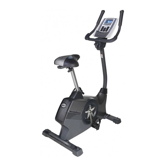
Model No. NTEVEX74911.0
Serial No.
Write the serial number in the
space above for reference.
Serial Number Decal
(under frame)
QUESTIONS?
If you have questions, or if there are
missing parts, please contact us:
UK
Call: 08457 089 009
From Ireland: 053 92 36102
Website: www.iconsupport.eu
E-mail: csuk@iconeurope.com
Write:
ICON Health & Fitness, Ltd.
c/o HI Group PLC
Express Way
Whitwood, West Yorkshire
WF10 5QJ
UK
AUSTRALIA
Call: 1-800-237-173
E-mail:
australiacc@iconfitness.com
CAUTION
Read all precautions and instruc-
tions in this manual before using
this equipment. Keep this manual
for future reference.
USER'S MANUAL
www.iconeurope.com
Advertisement
Table of Contents

Related Manuals for NordicTrack GX 4.1


Summary of Contents for NordicTrack GX 4.1
- Page 1 USER'S MANUAL Model No. NTEVEX74911.0 Serial No. Write the serial number in the space above for reference. Serial Number Decal (under frame) QUESTIONS? If you have questions, or if there are missing parts, please contact us: Call: 08457 089 009 From Ireland: 053 92 36102 Website: www.iconsupport.eu E-mail: csuk@iconeurope.com...
-
Page 2: Table Of Contents
User weight must not exceed 275 pounds. This product should always be used on a level surface. This product is not intended for therapeutic use. Replace label if damaged, illegible, or removed. NORDICTRACK is a registered trademark of ICON IP, Inc. -
Page 3: Important Precautions
IMPORTANT PRECAUTIONS WARNING: To reduce the risk of serious injury, read all important precautions and instructions in this manual and all warnings on your exercise bike before using your exercise bike. ICON assumes no responsibility for personal injury or property damage sustained by or through the use of this product. -
Page 4: Before You Begin
The GX 4.1 us. The model number and the location of the serial exercise bike provides an impressive selection of fea-... -
Page 5: Part Identification Chart
PART IDENTIFICATION CHART See the drawings below to identify the small parts needed for assembly. The number in parentheses below each drawing is the key number of the part, from the PART LIST near the end of this manual. The number following the key number is the quantity needed for assembly. -
Page 6: Assembly
ASSEMBLY • Assembly requires two persons. • In addition to the included tool(s), assembly requires the following tools: • Place all parts in a cleared area and remove one adjustable wrench the packing materials. Do not dispose of the packing materials until you complete all one Phillips screwdriver assembly steps. - Page 7 3. Loosen the Adjustment Knob (27) in the Frame (1) a few turns. Orient the Seat Post (6) as shown. Then, pull the Adjustment Knob (27) outward and insert Adjustment the Seat Post into the Frame (1). Holes Slide the Seat Post (6) upward or downward to the desired position, and release the Adjustment Knob (27).
- Page 8 5. Apply some of the included grease to an M6 x 70mm Bolt Set (50). Orient the Handlebar (5) and the Upright (4) as shown. While a second person holds the Handlebar (5) near the Upright (4), insert the Extension Wire (59) upward through the Handlebar.
- Page 9 7. Orient the Upright (4) assembly and the Pivot Cover (12) as shown. Slide the Pivot Cover (12) upward to the Handlebar (5). Tip: Bend and flex the Pivot Cover slightly to slide it over the Handlebar. Avoid pinching the wires. Connect the long receiver wire (A) to the Receiver Wire (B).
- Page 10 9. Identify the Right Pedal (21), which is marked with an “R.” Using an adjustable wrench, firmly tighten the Right Pedal (21) clockwise into the Right Crank Arm (19). Tighten the Left Pedal (not shown) counter- clockwise into the Left Crank Arm (not shown). Strap Adjust the strap on the Right Pedal (21) to the desired position, and press the ends of the...
-
Page 11: How To Use The Heart Rate Monitor
HOW TO USE THE HEART RATE MONITOR HOW TO PUT ON THE HEART RATE MONITOR rate monitor shuts off when it is removed and the electrode areas are dried. If the heart rate monitor is The heart rate monitor has two components: a chest not dried after each use, the battery may be drained strap and a sensor unit (see the drawing below). -
Page 12: How To Use The Exercise Bike
HOW TO USE THE EXERCISE BIKE HOW TO PLUG IN THE POWER ADAPTER HOW TO ADJUST THE HEIGHT OF THE SEAT IMPORTANT: If the exercise bike has been For effective exercise, the seat should be at the exposed to cold temperatures, allow it to warm to proper height. - Page 13 HOW TO ADJUST THE ANGLE OF THE HOW TO ADJUST THE PEDAL STRAPS HANDLEBAR To adjust the To adjust the angle of the handlebar, first loosen the pedal straps, first adjustment knob a few turns. Next, pull the knob out- pull the ends of ward, pivot the handlebar to the desired angle, and the straps off the...
- Page 14 CONSOLE DIAGRAM FEATURES OF THE CONSOLE With the iFit Live mode, you can download personal- ized workouts, create your own workouts, track your workout results, and access many other features. See The advanced console offers an array of features www.iFit.com for complete information. designed to make your workouts more effective and enjoyable.
- Page 15 HOW TO ACTIVATE THE CONSOLE Note: After you press the buttons, it will take a moment for the pedals to reach the selected resis- The included power adapter can be used to operate tance level. the exercise bike. See HOW TO PLUG IN THE 4.
- Page 16 Watts—This display will show your power output HOW TO USE A PRESET WORKOUT in watts. 1. Begin pedaling or press any button on the console to turn on the console. Change the volume level of the console by press- ing the Volume increase and decrease buttons. See HOW TO ACTIVATE THE CONSOLE on page Note: The console can show pedaling speed and distance in either miles or kilometers.
- Page 17 3. Begin pedaling to start the workout. IMPORTANT: The target speed is intended only to provide motivation. Your actual pedaling speed may be slower than the target speed. Each workout is divided into one-minute seg- Make sure to pedal at a speed that is comfort- ments.
- Page 18 HOW TO USE THE CONSTANT POWER WORKOUT If your power output is too far below or above the target watts setting, the resistance of the pedals 1. Begin pedaling or press any button on the will automatically increase or decrease to bring console to turn on the console.
- Page 19 HOW TO USE THE IFIT TRAINING MODE HOW TO USE THE INFORMATION MODE The optional iFit Live module allows your console to The console features an information mode that allows communicate with your wireless network and unlocks you to view usage information for the exercise bike, exciting new features.
- Page 20 4. Adjust the contrast level of the display if 7. Check the status of the iFit Live module if desired. desired. The currently selected contrast level will also To check the status of the iFit Live module, press appear in the display. To change the contrast level, the increase and decrease buttons until the bullet press the increase and decrease buttons until the appears next to the words CHECK WIFI STATUS...
-
Page 21: Maintenance And Troubleshooting
MAINTENANCE AND TROUBLESHOOTING Inspect and tighten all parts of the exercise bike regu- Next, rotate the larly. Replace any worn parts immediately. Left Crank Arm (20) to a vertical To clean the exercise bike, use a damp cloth and a position with the small amount of mild soap. - Page 22 HOW TO ADJUST THE DRIVE BELT Next, rotate the Right Crank Arm (19) to a vertical position with the end of the Right Crank Arm pointing If you can feel the pedals slip while you are pedaling, upward. even when the resistance is adjusted to the highest level, the drive belt may need to be adjusted.
-
Page 23: Exercise Guidelines
EXERCISE GUIDELINES WARNING: Burning Fat—To burn fat effectively, you must exer- cise at a low intensity level for a sustained period of Before beginning this time. During the first few minutes of exercise, your or any exercise program, consult your physi- body uses carbohydrate calories for energy. - Page 24 SUGGESTED STRETCHES The correct form for several basic stretches is shown at the right. Move slowly as you stretch—never bounce. 1. Toe Touch Stretch Stand with your knees bent slightly and slowly bend forward from your hips. Allow your back and shoulders to relax as you reach down toward your toes as far as possible.
-
Page 25: Part List
PART LIST Model No. NTEVEX74911.0 R0411A Key No. Qty. Description Key No. Qty. Description Frame Motor Bracket Front Stabilizer Resistance Motor Rear Stabilizer Resistance Disc Upright Resistance Arm Handlebar M6 x 70mm Bolt Set Seat Post M6 x 60mm Bolt Set Front Shield Cover Resistance Bracket Top Shield Cover... - Page 26 Key No. Qty. Description Key No. Qty. Description M4 x 5mm Patch Screw Plug Adapter Handlebar Pivot Bushing Sensor M4 x 19mm Flat Head Screw Strap M4 x 22mm Screw – Receiver Wire Power Receptacle/Wire – Assembly Tool Snap Ring –...
-
Page 27: Exploded Drawing
EXPLODED DRAWING Model No. NTEVEX74911.0 R0411A 81 82... -
Page 28: Ordering Replacement Parts
ORDERING REPLACEMENT PARTS To order replacement parts, please see the front cover of this manual. To help us assist you, be prepared to provide the following information when contacting us: • the model number and serial number of the product (see the front cover of this manual) •...