Table of Contents
Advertisement
Quick Links
Download this manual
See also:
Manual
Advertisement
Chapters
Table of Contents

Related Manuals for Omron E5CSV


Summary of Contents for Omron E5CSV
- Page 1 E5CSV E5CSV E5CSV E5CSV E5CSV E5CSV E5CS-U E5CS-U E5CS-U E5CS-U E5CS-U E5CS-U Digital Temperature Controller User's Manual Cat. No. H140-E1-02...
- Page 3 Conforms to UL, CSA, and IEC safety standards and EMC Directive. This manual describes the E5CSV and E5CS-U. Read this manual thoroughly and be sure you understand it before attempting to use the Compact Digital Temperature Controller and use the Compact Digital Temperature Controller correctly according to the information provided.
-
Page 4: Warranty And Limitations Of Liability
PRODUCTS, WHETHER SUCH CLAIM IS BASED ON CONTRACT, WARRANTY, NEGLIGENCE, OR STRICT LIABILITY. In no event shall the responsibility of OMRON for any act exceed the individual price of the product on which liability is asserted. IN NO EVENT SHALL OMRON BE RESPONSIBLE FOR WARRANTY, REPAIR, OR OTHER CLAIMS... - Page 5 Performance data given in this manual is provided as a guide for the user in determining suitability and does not constitute a warranty. It may represent the result of OMRON's test conditions, and the users must correlate it to actual application requirements. Actual performance is subject to the OMRON Warranty and Limitations of Liability.
-
Page 6: Safety Precautions
Safety Precautions Definition of Precautionary Information The following notation is used in this manual to provide precautions required to ensure safe usage of the product. The safety precautions that are provided are extremely important to safety. Always read and heed the information provided in all safety precautions. The following notation is used. - Page 7 Loose screws may occasionally result in fire. Tighten terminal screws to the specified torque (E5CSV: 0.74 to 0.90 N·m, E5CS-U: 0.5 N·m). Unexpected operation may result in equipment damage or accidents if the settings are not appropriate for the controlled system.
-
Page 8: Precautions For Safe Use
Precautions for Safe Use Be sure to observe the following precautions to prevent operation failure, malfunction, or adverse affects on the performance and functions of the product. Not doing so may occasionally result in unexpected events. 1) The product is designed for indoor use only. Do not use the product outdoors or in any of the following locations. - Page 9 13) A switch or circuit breaker should be provided close to this Unit. The switch or circuit breaker should be within easy reach of the operator, and must be marked as a disconnecting means for this unit. 14) Approximately 30 minutes is required for the correct temperature to be displayed after turning the power supply to the Temperature Controller ON.
-
Page 10: Installation Precautions
Waterproofing The degree of protection is as shown below. Sections without any specification on their degree of protection or those with IP@0 are not waterproof. E5CSV: Front panel IP66, rear case IP20, terminals IP00 E5CS-U: Front panel IP50, enclosure rating 2 (IEC 60529),... -
Page 11: Precautions For Operation
Do not subject the terminal screws to excessive stress (force) when tightening them. Make sure that there are no loose screws after tightening terminal screws to the specified torque (E5CSV: 0.74 to 0.9 N·m, E5CS-U: 0.5 N·m). Be sure to confirm the polarity for each terminal before wiring the terminal block and connectors. -
Page 12: Revision History
Revision History A manual revision code appears as a suffix to the catalog number on the back cover of the manual. H140-E1-02 Cat. No. The following table outlines the changes made to the manual during each revision. Page numbers refer to the previous version. -
Page 13: Conventions Used In This Manual
Conventions Used in This Manual Model Notations “E5CSV and E5CS-U” or “E5CSV/E5CS-U” are used when the information being provided applies to all E5CSV and E5CS-U Digital Temperature Controllers. Meanings of Abbreviations The following abbreviations are used in parameter names, figures and in text explanations. These... -
Page 14: About This Manual
Temperature Controllers for operation, including installation and wiring. Section 3 describes the basic ● Basic Operations Section 3 Basic operation of the E5CSV/E5CS-U Operations Digital Temperature Controllers, Section 5 Parameters including key operations to set parameters and descriptions of display elements based on specific control examples. -
Page 15: Table Of Contents
■ External Dimensions (Unit: mm)............2-2 ■ Panel Cutout Dimensions (Unit: mm) ..........2-2 ■ Mounting..................... 2-3 ■ Removing the E5CSV from the Case..........2-3 2.2 Wiring Terminals ....................2-5 ■ Terminal Arrangement ................ 2-5 ■ Precautions when Wiring..............2-5 ■... - Page 16 ■ Changing the SP ................3-7 3.6 Using ON/OFF Control..................3-8 ■ ON/OFF Control ................. 3-8 3.7 Determining PID Constants (AT, ST, Manual Setup).......... 3-9 ■ AT (Auto-tuning).................. 3-9 ■ ST (Self-tuning) ................3-10 ■ Manual Setup ................... 3-12 3.8 Alarm Outputs ....................3-14 ■...
-
Page 18: Section 1 Overview
■ Using the Keys............1-3 ● M (Mode) Key ............1-3 ● U (Up) Key............1-3 ● D (Down) Key ............1-3 ● Lock Release Key (E5CSV only)......1-3 1.2 I/O Configuration and Main Functions ....... 1-4 ■ I/O Configuration............1-4 ● E5CSV and E5CS-U ...........1-4 ■... -
Page 19: Names Of Parts
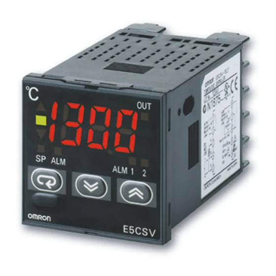
Section 1 Overview 1.1 Names of Parts ■ Front Panel ● E5CSV ● E5CS-U Deviation indicators Temperature display Tool insertion hole Temperature display Deviation Output indicator indicators Output indicator Mode Alarm indicators indicators Alarm indicators Mode Up Key Mode Key... -
Page 20: Using The Keys
Holding the key down speeds up the decrementation. ● Lock Release Key When the protect switch is ON, the set value can be changed by pressing the U and D Keys while holding down the Lock Release (E5CSV only) Key. -
Page 21: I/O Configuration And Main Functions
1 assignment, and the alarm 2 assignment in the initial setting level. ■ Basic Model Number ● Models with Terminal Blocks E5CSV - @ @ @ @ -@ Case color Blank: Black W : Light gray... -
Page 22: Control Outputs
● Alarms • Alarms are supported by E5CSV-@1@@-@, E5CSV-@2@@-@, E5CS-@1@@U-@, and E5CS-@2@@U-@. Set the alarm classification and alarm value or the alarm's upper and lower limits. If necessary, a more comprehensive alarm function can be achieved by setting the standby sequence, close in alarm/open in alarm, and alarm latch parameters. -
Page 23: Setting Level Configuration And Key Operations
Parameters are divided into groups, each called a “level.” Each of the set values (setting items) in these levels is called a “parameter.”. The parameters on the E5CSV/E5CS-U are divided as follows: When the power is turned ON, “0” will be displayed for approximately one second. -
Page 24: Selecting Parameters
1.3 Setting Level Configuration and Key Operations ■ Selecting • Within each level, the parameter is changed each time the M Key is pressed. Parameters The parameter changes immediately after pressing the M key. Parameter Parameter Parameter Parameter ■ Fixing Settings •... -
Page 25: Setting Switches
Section 1 Overview 1.4 Setting Switches ● E5CSV • Insert the tool (refer to the diagram) into the two tool insertion holes (one on the top and one on the bottom) and release the hooks. Then, grip the front panel and pull out towards you to remove it. -
Page 26: Protect Switch
1.4 Setting Switches Control mode switches INIT switch Temperature range switch Protect switch Alarm mode switch ● Protect Switch • When the protect switch is ON, Up Key and Down Key operations are prohibited to prevent setting mistakes. • The Mode Key, however, can also be operated even if the protect switch is ON. -
Page 27: Temperature Range Switch
Section 1 Overview ● Temperature • Set the temperature range using the temperature range switch numbers. Range Switch Thermocouple input (E5CSV-@ KJ, E5CS-@ KJU) Tem- Set range Speci- per- fica- °C °F ature tions range J or L * The default is 2. - Page 28 °C °F ature tions range − 50 − 50 − 50 − 50 * The default is 1. Multi-input (thermocouple/platinum resistance thermometer) models (E5CSV-@T, E5CS-@TU) Control mode switch 5: OFF Tem- Setting range Speci- per- fica- °C °F ature tions range −...
-
Page 29: Alarm Mode Switch
Section 1 Overview ● Alarm Mode • Select the alarm mode switch number when changing to the alarm mode. This switch is not provided in models without alarms.) Switch Alarm output Alarm type value operation Alarm function OFF Output OFF Upper- and lower-limit Upper-limit Lower-limit... -
Page 30: Section 2 Preparations
● E5CS-U............... 2-3 ● Mounting to the Panel ......... 2-3 ● Mounting the Terminal Cover ......2-3 ■ Removing the E5CSV from the Case ......2-3 2.2 Wiring Terminals ..............2-5 ■ Terminal Arrangement ..........2-5 ● E5CSV ..............2-5 ●... -
Page 31: Installation
94.45 (7.75) 6.25 72.5 14.2 44.8 44.8 ■ Panel Cutout Dimensions (Unit: mm) ● E5CSV and E5CS-U Individual Mounting Group Mounting (48 × Number of Units – 2.5) +1.0 +0.6 • The recommended panel thickness is 1 to 4 mm. -
Page 32: Mounting
0.29 to 0.39 N·m. ● Mounting the For the E5CSV, make sure that the “UP” mark is facing up, and then fit the terminal cover into the holes on the top and bottom. Terminal Cover * Order the E53-COU10 Terminal Cover separately. - Page 33 Be sure not to impose excessive force on the panel. (3) When inserting the E5CSV, check to make sure that the sealing rubber is in place and push the E5CSV toward the rear case until it snaps into position. While pushing the E5CSV into place, push down on the hooks on the top and bottom surfaces of the rear case so that the hooks are securely locked in place.
-
Page 34: Wiring Terminals
2.2 Wiring Terminals 2.2 Wiring Terminals ■ Terminal Arrangement ● E5CSV Relay output Alarm output (relay output), ① ⑥ 250 VAC, 3 A 250 VAC, 1 A (resistive load) (Resistive load) Control output ② ⑦ Alarm 2 − Voltage output... -
Page 35: Precautions When Wiring
● Power Supply • With the E5CSV, connect to terminals 9 and 10. For the E5CS-U with alarms, connect to terminals 10 and 11, and for E5CS-U models without alarms, connect to terminals 7 and 8. The following table shows the specifications. -
Page 36: Control Outputs
2.2 Wiring Terminals ● Control Outputs • Outputs are sent from terminals 1 and 2 with the E5CSV, and from terminals 4 to 6 with the E5CS-U. The following diagrams show the available outputs and their internal equalizing circuits. ④... -
Page 37: Section 3 Basic Operations
Section 3 Basic Operations 3.1 Setting the Input Type ..............3-2 ■ Input Type ..............3-2 ● Thermocouple............. 3-2 ● Platinum Resistance Thermometer..... 3-2 ● Thermistor ............3-3 ● Multi-input (Thermocouple/Platinum Resistance Thermometer) Models ........3-3 3.2 Selecting the Temperature Unit ............ 3-4 ●... -
Page 38: Setting The Input Type
Section 3 Basic Operations 3.1 Setting the Input Type The E5CS is available in models with thermocouple input, models with platinum resistance thermometer input, thermistor input, and multi-input (thermocouple/platinum resistance thermometer) models. The type of Sensor that can be used depends on the model. Confirm the model that was purchased, and set the Sensor to be used and the temperature range switch. -
Page 39: Thermistor
3.1 Setting the Input Type ● Thermistor Temper- Specifications Input temperature range ature range (°F) 6 KΩ (0°C) (°C) (°F) 6 KΩ (0°C) (°C) (°F) 30 KΩ (0°C) (°C) 550 Ω (200°C) (°F) (°C) (°F) 4 KΩ (200°C) (°C) (°F) 6 KΩ... -
Page 40: Selecting The Temperature Unit
Section 3 Basic Operations 3.2 Selecting the Temperature Unit ● Temperature Unit Select the temperature unit as either °C or °F using the control • mode switch 6. • The default is OFF (°C). -
Page 41: Selecting Pid Control Or On/Off Control
3.3 Selecting PID Control or ON/OFF Control 3.3 Selecting PID Control or ON/OFF Control Two control methods are supported: 2-PID control and ON/OFF control. Switching between 2-PID control and ON/OFF control is performed using the control mode switch 1. When this parameter is set to ON, 2-PID control is selected, and when it is set to OFF, ON/OFF control is selected. -
Page 42: Setting Output Specifications
Section 3 Basic Operations 3.4 Setting Output Specifications ■ Control Period • Set the output period (control period). Though a shorter period provides better control performance, it is recommended that the control period be set to 20 seconds or longer for a relay output to preserve the service life of the relay. -
Page 43: Setting The Set Point (Sp)
3.5 Setting the Set Point (SP) 3.5 Setting the Set Point (SP) The operation level is displayed when the power is turned ON. When the M Key is used to light the SP indicator in the display, the set point is displayed. -
Page 44: Using On/Off Control
Section 3 Basic Operations 3.6 Using ON/OFF Control In ON/OFF control, the control output turns OFF when the temperature being controlled reaches the preset set point. When the manipulated variable turns OFF, the temperature begins to fall and the control turns ON again. This operation is repeated over a certain temperature range. At this time, the amount that the temperature must fall before control turns ON again is determined by the “hysteresis”... -
Page 45: Determining Pid Constants (At, St, Manual Setup)
3.7 Determining PID Constants (AT, ST, Manual Setup) 3.7 Determining PID Constants (AT, ST, Manual Setup) ■ AT (Auto-tuning) • When AT is executed, the optimum PID constants for the set point at that time are set automatically. A method (called the limit cycle method) for forcibly changing the manipulated variable and finding the characteristics of the control target is employed. -
Page 46: St (Self-Tuning)
Section 3 Basic Operations ■ ST (Self-tuning) ST (self-tuning) is a function that finds PID constants by using step response tuning (SRT) when Controller operation begins or when the set point is changed. Once the PID constants have been calculated, ST is not executed when the next control operation is started as long as the set point remains unchanged. -
Page 47: St Stable Range
3.7 Determining PID Constants (AT, ST, Manual Setup) ● ST Stable Range The ST stable range determines the set value under which ST Operating Procedure (self-tuning) functions operate. This procedure sets the ST stable range to 20°C. Initial setting level (1) Press the M Key from the initial setting level (1) and select “ST stable range”... -
Page 48: Manual Setup
Section 3 Basic Operations ■ Manual Setup The manual settings for PID constants are performed separately in the “proportional band” (P), “integral time” (I), and “derivative time” (D) parameters in the initial setting level (2). When PID constants are set manually, the tuning setting enabled in the initial setting level (1) is automatically changed to AT (auto-tuning), and ST (self-tuning) is disabled. - Page 49 3.7 Determining PID Constants (AT, ST, Manual Setup) • When P (Proportional Band) Is Adjusted The curve rises gradually, and a long stabilization time is created, Increas- but overshooting is prevented. ing P Overshooting and hunting occur, but the set value is quickly reached creas and the temperature stabilizes.
-
Page 50: Alarm Outputs
Section 3 Basic Operations 3.8 Alarm Outputs • Alarms can be used with E5CS@1@@-@ (one alarm point), E5CS@2@@-@ (two alarm points), E5CS@1@@U-@ (one alarm point), and E5CS@2@@U-@ (two alarm points). Alarm output conditions are determined by a combination of the “alarm type” and “alarm value”. •... - Page 51 3.8 Alarm Outputs Alarm mode switch Set the alarm mode switch to 2 and then turn ON the power. Press the M Key in the operation level and select the “alarm value 1” (ALM mode) parameter. Power ON Process value Use the U Key to set the parameter to 10.
-
Page 52: Shifting Input Values
Section 3 Basic Operations 3.9 Shifting Input Values ■ Shifting Inputs When the control mode switch 4 is set to ON, the input shift value is displayed in the operation level and the shift can be added to the input. When the control mode switch 4 is set to OFF (no input shift display), the input shift is not displayed but the shift value is enabled. -
Page 53: Shift Method
3.9 Shifting Input Values ● Shift Method Make sure that the control target temperature (C) and Controller temperature (B) match, with the control target temperature near the set point. Check the control target temperature (B) and the Controller readout (A). Subtract the Controller readout temperature (A) from the control target temperature (B) Set the result as the input shift value. -
Page 54: Section 4 Operations For Applications
Section 4 Operations Applications • • • 4.1 Moving to the Initial Setting Level ........4-2 4.2 Assigning Outputs .............4-3 ■ Output Assignment ............ 4-3 4.3 Alarm Functions ..............4-4 ■ Alarm Hysteresis ............4-4 ■ Standby Sequence ............ 4-4 ■ Alarm Latch ............... 4-4 ●... -
Page 55: Moving To The Initial Setting Level
Section 4 Operations for Applications 4.1 Moving to the Initial Setting Level • To move to the initial setting level, turn OFF the protect switch, turn ON the INIT switch, and then hold down the U Key while turning ON the power. -
Page 56: Assigning Outputs
4.2 Assigning Outputs 4.2 Assigning Outputs • ■ Output • By changing the control output assignment, alarm output 1 assignment, and alarm output 2 assignment settings, the functions Assignment assigned to each output can be changed in the initial setting level (3). -
Page 57: Alarm Functions
Section 4 Operations for Applications 4.3 Alarm Functions • ■ Alarm • The hysteresis of alarm outputs when alarms are switched ON/OFF can be set as follows: Hysteresis Alarm hysteresis is always 0.2 (°C or °F). Lower-limit alarm Upper-limit alarm Alarm hysteresis Alarm hysteresis Alarm value... -
Page 58: Close In Alarm/Open In Alarm
4.3 Alarm Functions ■ Close in • When “close in alarm” is set, the status of the alarm function will be output as is. When “open in alarm” is set, the status of the alarm Alarm/Open in function will be reversed before being output. Alarm •... -
Page 59: Setting The Sp Upper And Lower Limit Values
Section 4 Operations for Applications 4.4 Setting the SP Upper and Lower Limit Values • ■ Set Point The setting range of the set point is limited by the set point limiter. The set point limiter is used to prevent the control target from Limiter reaching abnormal temperatures. -
Page 60: Setting The Sp Upper And Lower Limit Values
4.4 Setting the SP Upper and Lower Limit Values • Setting the Set Point Upper-limit Value • Set Point Upper Limit = 1000 Operating Procedure Initial setting level (3) Press the M Key from the initial setting level (3) and select “set point upper limit”... -
Page 61: Alarm Delays
Section 4 Operations for Applications 4.5 Alarm Delays • ■ Alarm Delays • Delays can be set for the alarm outputs. ON and OFF delays can be set separately for alarms 1 and 2. The ON and OFF delays for alarms 1 and 2 also apply to the individual ALM1 and ALM2 indicators. -
Page 62: Parameters Related To Alarm Delays
4.5 Alarm Delays ● Parameters Related to Alarm Delays Set (monitor) Parameter name Setting values Initial setting level (4) Alarm 1 ON Delay 0 to 999 (s) SP mode Initial setting level (5) Alarm 2 ON Delay 0 to 999 (s) SP mode Initial setting level (4) Alarm 1 OFF Delay... - Page 63 Section 4 Operations for Applications 4-10...
-
Page 64: Section 5 Parameters
Section 5 Parameters 5.1 Conventions Used in this Section..........5-2 ● Meanings of Icons Used in this Section ....5-2 ● About Related Parameter Displays ..... 5-2 ● The Order in Which Parameters Are Described in This Section ........5-2 5.2 Operation Level ................ -
Page 65: Conventions Used In This Section
Section 5 Parameters 5.1 Conventions Used in this Section ● Meanings of Icons Used in this Section Describes the functions of the parameter. Function Describes the setting range and default of the parameter. Setting ● About Related Parameter Displays Parameters are displayed only when the conditions of use indicated for the parameter are satisfied. -
Page 66: Operation Level
5.2 Operation Level 5.2 Operation Level Display this level to perform standard control operations. The set points and alarm values are set in this level. Operation Level Power ON Page O U T IS mode (1) ・ Input shift value Page (when input shift is Process value... - Page 67 Section 5 Parameters Process value • Displays the process value (except when no PV display is selected) Monitor range Unit Process Input indication range Function value (See pages A-12 and A-13.) * The decimal position is set automatically by the selected Sensor. SP mode Set point •...
- Page 68 5.2 Operation Level ALM2 mode Alarm value 2 This parameter is set to the input values “X” or “Y” in the alarm type list. The ALM will flash in the display while the alarm value 2 is displayed. • This parameter sets the alarm value for alarm output 2. Function Alarm Setting range...
- Page 69 Section 5 Parameters IS mode (1) Manual reset value • This function resets the offset that occurs when P (or PD) control is used. The offset that occurs is set in °C or °F as the manual reset value. (This applies when manual reset is enabled.) Function •...
- Page 70 5.2 Operation Level IS mode (3) Alarm 1 latch status • This parameter displays the alarm 1 latch status. The latch can be cleared by pressing the U and D Keys for at least 2 s while • the alarm 1 latch status is displayed. Function •...
-
Page 71: Moving To The Initial Setting Level
Section 5 Parameters 5.3 Moving to the Initial Setting Level The initial setting level is used to make the settings that maximize Temperature Controller performance. Control stops when moving to the initial setting level. The methods for moving to the initial setting level are described here. -
Page 72: Initial Setting Level(1)
5.4 Initial Setting Leve l (1) 5.4 Initial Setting Level (1) Move to initial setting level (1) by selecting “1” in the initial setting level selection display and pressing the M Key. This level is used to set the following parameters including tuning, hysteresis for ON/OFF control. - Page 73 Section 5 Parameters PV auto reset PV/SP display Tuning selection SP mode ST executing display Manual reset enable/disable Control period selection • Set whether to enable or disable PV auto reset. • Set the PV/SP display. • Select the tuning method. •...
-
Page 74: Initial Setting Level (1)
5.4 Initial Setting Leve l (1) 100’s digit 10’s digit 1’s digit Manual Displayed Control PV auto PV/SP Tuning reset number execution period Setting reset display selection enable/ display selection disable Disabled ST/AT 2/20 Disabled PV→SP Enabled 6/60 Enabled 2/20 Enabled ST/AT 6/60... -
Page 75: Indicator Lights
Section 5 Parameters Integral time setting unit Hysteresis width ALM mode Temperature width in which the ■ deviation indicator lights • Select the integral time setting unit. • Set the hysteresis width. Set the temperature width in which the ■ deviation indicator lights. •... -
Page 76: Initial Setting Level (2)
5.4 Initial Setting Leve l (1) IS mode ST stable range • The setting of this parameter determines when ST operates. Function Setting range Unit Default °C/°F 1 to 999 Setting 5-13... -
Page 77: Initial Setting Level (2)
Section 5 Parameters 5.5 Initial Setting Level (2) Move to initial setting level (2) by selecting “2” in the initial setting level selection display and pressing the M Key. Manual PID settings can be set in this level. In the initial setting level (2), the ▲■▼deviation indicators are lit. Initial setting level (2) Page O U T... -
Page 78: Initial Setting Level (3)
5.5 Initial Setting Level (2) SP mode Proportional band The proportional band (P) is set in this parameter. The proportional band for AT (auto-tuning) and ST (self-tuning) can also be set automatically. • P operation: Refers to control in which the MV is proportional to the deviation. Function Setting range Unit... -
Page 79: Initial Setting Level (3)
Section 5 Parameters 5.6 Initial Setting Level (3) Move to initial setting level (3) by selecting “3” in the initial setting level selection display and pressing the M Key. The set point upper-/lower-limit values and output assignment can be set in this level. In the initial setting level (3), the ▲... -
Page 80: Initial Setting Level (4)
5.6 Initial Setting Level (3) SP mode SP upper limit • This parameter sets the upper limit of the set point. The set point can be set within the range with the upper limit set in the “SP upper limit” parameter. If this parameter is reset, however, any set point that is outside of the new Function range will be forcibly changed to the SP upper limit. - Page 81 Section 5 Parameters IS mode (1) Control output assignment • This parameter sets the function to be assigned to the control output. Function Displayed Set value Setting range Default number No assignment Setting Control function 0 to 3 1: Control function Alarm 1 function Alarm 2 function IS mode (2)
-
Page 82: Initial Setting Level (5)
5.6 Initial Setting Level (3) IS mode (3) Alarm 2 assignment • This parameter sets the function to be assigned to alarm output 2. Function Displayed Set value Setting range Default number Setting No assignment Control function 0 to 3 3: Alarm 2 function Alarm 1 function Alarm 2 function... -
Page 83: Initial Setting Level (4)
Section 5 Parameters 5.7 Initial Setting Level (4) Move to initial setting level (4) by selecting “4” in the initial setting level selection display and pressing the M Key. The settings related to the alarm 1 ON/OFF delay and alarm 1 can be set in this level. In the initial setting level (4), the ▲■... - Page 84 5.7 Initial Setting Level (4) SP mode Alarm 1 ON delay Alarm 1 function is prevented from turning ON until after the delay time set in this parameter has elapsed. • Set the time for which the ON delay is to be enabled. •...
- Page 85 Section 5 Parameters IS mode (1) Alarm 1 type • Select one of the following nine alarm 1 types: • This parameter is displayed only for models without alarm outputs (i.e., models without an alarm mode switch). Settings for models with alarm Function outputs are set using the alarm mode switch.
- Page 86 5.7 Initial Setting Level (4) IS mode (2) Alarm 1 open in alarm • This parameter sets the output status for alarm 1. • When “close in alarm” is set, the status of the alarm 1 function will be output as is.
-
Page 87: Initial Setting Level (5)
Section 5 Parameters 5.8 Initial Setting Level (5) Move to initial setting level (5) by selecting “5” in the initial setting level selection display and pressing the M Key. The settings related to the alarm 2 ON/OFF delay and alarm 2 can be set in this level. In the initial setting level (5), the ▼... - Page 88 5.8 Initial Setting Level (5) SP mode Alarm 2 ON delay Alarm 2 function is prevented from turning ON until after the delay time set in this parameter has elapsed. • Set the time for which the ON delay is to be enabled. •...
- Page 89 Section 5 Parameters IS mode (1) Alarm 2 type • Select one of the following nine alarm 2 types: Function Alarm output Alarm type value operation Setting Alarm function OFF Output OFF Upper- and lower-limit Upper-limit Lower-limit Upper- and lower-limit range Upper- and lower-limit with standby sequence Upper-limit with standby...
- Page 90 5.8 Initial Setting Level (5) IS mode (2) Alarm 2 open in alarm • This parameter sets the output status for alarm 2. • When “close in alarm” is set, the status of the alarm 2 function will be output Function as is.
-
Page 91: Appendices
Appendices Specifications ................. A-2 ■ Ratings................A-2 ■ Characteristics ..............A-3 Error Displays ................. A-4 Burnout/Short-circuit Display and Causes....... A-7 Parameter Operation Lists ............A-8 Sensor Input Setting Range, Indication Range, Control Range ..............A-12 Setting Levels Diagram ............A-14 Parameter Flow ..............A-15... -
Page 92: Specifications
Multi-input (thermocouple/platinum resistance thermometer) type: K, J, L, T, U, N, R, Pt100, JPt100 Control output SPST-NO, 250 VAC, 3A (resistive load) Electrical E5CSV durability: 100,000 operations Min. applicable load: 5 V, 10 mA Relay output SPDT, 250 VAC, 3A (resistive load) -
Page 93: Characteristics
R: ±3°C ±1 digit max. at 200°C or less The following exceptions apply to platinum resistance thermometers. Input set values 0, 1, 2, 3 for E5CSV: 0.5% FS ±1 digit max. • Input set value 1 for E5CS-U: 0.5% FS ±1 digit max. -
Page 94: Error Displays
Appendices Error Displays When an error occurs, the error contents are shown on the display window. This section describes how to check error codes on the display, and the actions to be taken to remedy the problems. Overflow ● Meaning (1) The process value is higher than the control temperature range. - Page 95 Error Displays Input Sensor Error (High Temperature) Flashing ● Meaning (1) The process value is higher than the overflow temperature or a sensor error has occurred when using a thermocouple input or platinum resistance thermometer input model. (2) The process value is higher than the control temperature range or sensor error occurred...
- Page 96 Appendices Display Range Exceeded ● Meaning This does not indicate an error. It is displayed if the process value exceeds the display range when the control range is larger than the display range. When less than −99 • When more than 1999 : •...
-
Page 97: Burnout/Short-Circuit Display And Causes
Burnout/Short-circuit Display and Causes Burnout/Short-circuit Display and Causes The display window shows the error details if an input sensor burnout or short-circuit occurs. The error display and control output operation for burnouts and short-circuits is explained below for each input type. ●... -
Page 98: Parameter Operation Lists
Appendices Parameter Operation Lists ■ Operation Level Mode indicators/ Parameters Setting (monitor) value Default Unit displayed value text − Process value Sensor input indication range Set point SP mode SP lower limit to SP upper limit Alarm value 1 ALM mode 1 to 7: 0 to input setting range full scale 8: Input setting range lower-limit value to input setting range upper-limit value... - Page 99 Parameter Operation Lists ■ Initial Setting Level (1) Mode indicators/ Parameters Setting (monitor) value Default Unit value displayed text SP mode PV auto reset 0: No None 100’s digit 1: Yes PV/SP display SP mode PV/SP display Tuning selection None Tuning selection 10’s digit PV→SP...
- Page 100 Appendices ■ Initial Setting Level (2) Mode indicators Parameters Setting (monitor) value Default Unit /displayed value text Proportional band 1 to 999 °C/°F SP mode Integral time 0 to 1999 Second ALM mode 0 to 99 Minute Derivative time 0 to 1999 Second IS mode ■...
- Page 101 Parameter Operation Lists ■ Initial Setting Level (4) Mode indicators Parameters Setting (monitor) value Default Unit /displayed value text Alarm 1 ON delay SP mode 0 to 999 Second Alarm 1 OFF delay ALM mode 0 to 999 Second Alarm 1 type IS mode 0, 9: No alarm None...
-
Page 102: Sensor Input Setting Range, Indication Range, Control Range
Appendices Sensor Input Setting Range, Indication Range, Control Range Specifica- Temperature Input type Input temperature range Control range tions range −20 to 220 (°C)/ −20 to 220 (°F) 0 to 200 (°C)/0 to 200 (°F) −30 to 330 (°C)/ −30 to 330 (°F) 0 to 300 (°C)/0 to 300 (°F) −40 to 440 (°C)/ −40 to 440 (°F) 0 to 400 (°C)/0 to 400 (°F) - Page 103 Sensor Input Setting Range, Indication Range, Control Range Specifica- Temperature Input type Input temperature range Control range tions range −99 to 850 (°C)/ −99 to 1,500 (°F) −119 to 870 (°C)/ −139 to 1,540 (°F) −20.0 to 219.9 (°C)/ −40.0 to 239.9 (°F) 0.0 to 199.9 (°C)/0.0 to 199.9 (°F) Multi-input −99 to 99 (°C)/ −99 to 99 (°F)
-
Page 104: Setting Levels Diagram
Setting Levels Diagram Setting Levels Diagram This diagram shows all of the setting levels. Some parameters are not displayed depending on the protect level setting and the conditions of use. Control is stopped for each of the initial setting levels. :... -
Page 105: Parameter Flow
Parameter Flow Parameter Flow This section describes the parameters set in each level. Pressing the M key at the last parameter in each level returns to the top parameter in that level. Power ON Protect switch = OFF INIT switch = ON Hold down the U Key. - Page 106 Parameter Flow O U T O U T O U T A LM A LM A LM A LM A LM A LM Initial setting level (5) Initial setting level (3) Initial setting level (4) Initial setting (3) Initial setting (4) O U T O U T O U T...
- Page 107 ................3-8 execution/ cancelled ............3-9 hysteresis width ..............5-12 AT execute/cancel ...............5-6 I/O configuration ..............1-4 basic model number............1-4 E5CSV and E5CS-U............1-4 E5CS-U ................1-4 main functions..............1-4 E5CSV................1-4 INIT switch................. 1-9 burnout ................A-7 initial setting level .............. 1-6...
- Page 108 ..............1-9 PV/SP display..............5-10 key operations ..............1-6 ratings ................A-2 lock release key..............1-3 Removing the E5CSV from the Case ........ 2-3 M (mode) key ..............1-3 sensor input setting range, indication range, control range main functions ..............1-4 ..................A-12 manual reset ..............5-10...
- Page 109 3-4 setting the SP upper and lower limit values .......4-6 terminal arrangement............2-5 shift method ..............3-17 E5CS-U ................2-5 shifting input values............3-16 E5CSV ................2-5 shifting inputs ..............3-16 tuning ................5-10 short-circuit................ A-7 SP ..................1-2 U (up) key ................. 1-3 SP lower limit ..............5-17...
- Page 110 The Netherlands IL 60173-5302 U.S.A. Tel: (31)2356-81-300/Fax: (31)2356-81-388 Tel: (1) 847-843-7900/Fax: (1) 847-843-7787 © OMRON Corporation 2005 All Rights Reserved. OMRON (CHINA) CO., LTD. OMRON ASIA PACIFIC PTE. LTD. In the interest of product improvement, Room 2211, Bank of China Tower, No.