Advertisement
Table of Contents
- 1 Ordering Information
- 2 Specifications
- 3 Installation
- 4 Terminal Cover
- 5 Operation
- 6 Operation Settings
- 7 Alarm Modes
- 8 Using the Control Mode Switches
- 9 Protect Switch
- 10 Precautions for Safe Use
- 11 Service Life
- 12 Measurement Accuracy
- 13 Precautions for Correct Use
- 14 Warranty and Application Considerations
- Download this manual
Temperature Controllers
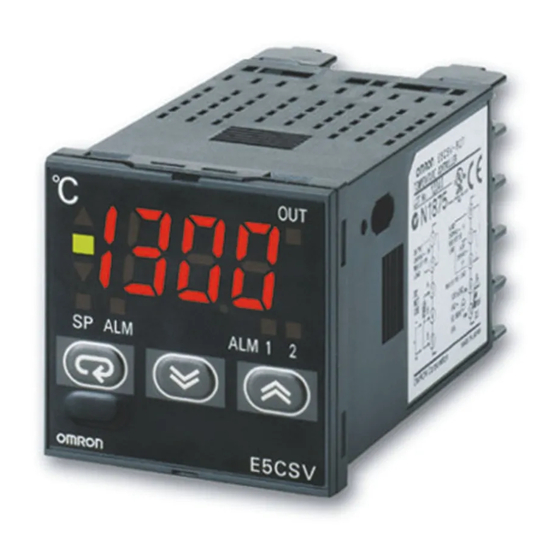
E5CSV
Easy Setting Using DIP Switch and Simple
Functions in DIN 48 x 48 mm-size
Temperature Controllers
• Easy setting using DIP and rotary switches.
• Multi-input (thermocouple/platinum resistance thermometer).
• Clearly visible digital display with character height of 13.5 mm.
• RoHS compliant.
Model Number Structure
■ Model Number Legend
Models with Terminal Blocks
E5CSV-@ 1 T @ -500
1 2 3 4
5
1. Output type
R: Relay
Q: Voltage for driving SSR
2. Number of alarms
1:
1 alarm
Ordering Information
■ List of Models
Size
Power supply
voltage
1/16 DIN
100 to 240 VAC
48 x 48 x 78 mm
(W x H x D)
24 VAC/VDC
■ Accessories (Order Separately)
Protective Front Cover
Type
Hard Protective Cover
Y92A-48B
3. Input type
T:
Thermocouple/platinum resistance
thermometer (multi-input)
Number of
Control output
alarm points
1
Relay
Voltage (for driving SSR)
1
Relay
Voltage (for driving SSR)
Model
4. Power supply voltage
Blank: 100 to 240 VAC
D:
5. Terminal cover
500:
TC/Pt multi-input
Incl. terminal cover
E5CSV-R1T-500
E5CSV-Q1T-500
E5CSV-R1TD-500
E5CSV-Q1TD-500
Temperature Controllers
24 VAC/VDC
Finger protection cover
E5CSV
1
Advertisement
Table of Contents

Related Manuals for Omron E5CSV


Summary of Contents for Omron E5CSV
-
Page 1: Ordering Information
Functions in DIN 48 x 48 mm-size Temperature Controllers • Easy setting using DIP and rotary switches. • Multi-input (thermocouple/platinum resistance thermometer). • Clearly visible digital display with character height of 13.5 mm. • RoHS compliant. Model Number Structure ■ Model Number Legend... -
Page 2: Specifications
Thermocouple (See note 1.): (±0.5% of indication value or ±1° C, whichever is greater) ±1 digit max. Platinum resistance thermometer (See note 2.): (±0.5% of indication value or ±1° C, whichever is greater) ±1 digit max. Indication accuracy (ambient temperature of 23° C) -
Page 3: Installation
3. Push the adapter from the terminals up to the panel, and temporarily fasten the E5CSV. 4. Tighten the two fastening screws on the adapter. Alternately tighten the two screws little by little to maintain a balance. Tighten the screws to a torque of 0.29 to 0.39 N·m. -
Page 4: Operation
3. When inserting the E5CSV, check to make sure that the sealing rubber is in place and push the E5CSV toward the rear case until 1. Insert the tool into the two tool insertion holes (one on the top and it snaps into position. While pushing the E5CSV into place, push one on the bottom) and release the hooks. - Page 5 -99 will be displayed as “[[[“ and values above 1,999 will be displayed as “]]].” Press for 2. If unit is changed to 1 degree when the SP and alarm value for at least 2 s. AT execution in progress the temperature range are displayed in 0.1-units from 0.0 to...
-
Page 6: Operation Settings
Alarm output Note: Turn OFF the power before changing the DIP switch settings on the E5CSV. Each of the switch settings will be enabled after the power is turned ON. For details on the position of the temperature range switch, control mode switches, and alarm mode switch, refer to page 4. -
Page 7: Using The Control Mode Switches
4. Using the Control Mode Switches (1) Using ON/OFF Control and PID Control (1.1) ON/OFF Control The control mode is set to ON/OFF control as the default setting. To perform cooling control of freezers, etc., turn ON switch 3. Switch 1 OFF: ON/OFF control... -
Page 8: Protect Switch
0 to 1999 0 to 400 Note: The control range for multi-input (thermocouple/platinum resistance thermometer) models is -40 to +40° F of each temperature range. The previous name J-DIN has been changed to L in accordance with revisions to DIN standards. - Page 9 Note: In models with an alarm, fff appears or flashes on the display to indicate that the temperature has exceeded the maximum display temperature and the output is set according to the alarm mode. In the same way, --- appears or flashes on the display to indicate that the temperature has exceeded the minimum display temperature and the output is set according to the alarm mode.
-
Page 10: Precautions For Safe Use
AWG18 (equal to a cross-sectional area of 0.205 to 0.832 mm Unexpected operation may result in equipment damage (The stripping length is 5 to 6 mm.) Up to two wires of the same or accidents if the settings are not appropriate for the size and type, or two crimp terminals can be inserted into a single controlled system. -
Page 11: Service Life
11.When using PID operation (self-tuning), turn ON the power supply humidity ranges: to the load (e.g., heater) at the same time or before turning the power supply to the Temperature Controller ON. If power is turned Temperature: -10 to 55° C (with no icing or condensation) -
Page 12: Warranty And Application Considerations
CONTRACT, WARRANTY, NEGLIGENCE, OR STRICT LIABILITY. In no event shall the responsibility of OMRON for any act exceed the individual price of the product on which liability is asserted. IN NO EVENT SHALL OMRON BE RESPONSIBLE FOR WARRANTY, REPAIR, OR OTHER CLAIMS REGARDING THE...