Lennox icomfort Setup Manual
Touch screen programmable communicating thermostat
Hide thumbs
Also See for icomfort:
- Owner's manual (26 pages) ,
- Quick start manual (12 pages) ,
- Quick start manual (4 pages)
Table of Contents
Advertisement
E2009 Lennox Industries Inc.
Dallas, Texas, USA
*2P1109*
INSTALLER'S SYSTEM SETUP
GUIDE
icomfortt
Thermostat
Touch Screen Programmable Communicating Thermostat
CONTROLS
506052−01
11/09
Shipping and Packing List1
1 −
icomfortt Touch Screen Communicating, 7−day Programmable
Thermostat
6 −
Mounting Screws
6 −
Wall Anchors
1 each − Installation Quick-Start Guide, Installer's System Setup Guide,
Homeowner's Manual, Warranty card, Warranty Audit tag
*P506052-01*
Litho U.S.A.
Advertisement
Table of Contents

Related Manuals for Lennox icomfort


Summary of Contents for Lennox icomfort
- Page 1 INSTALLER’S SYSTEM SETUP GUIDE E2009 Lennox Industries Inc. icomfortt Dallas, Texas, USA Thermostat Touch Screen Programmable Communicating Thermostat CONTROLS 506052−01 Litho U.S.A. 11/09 Shipping and Packing List1 1 − icomfortt Touch Screen Communicating, 7−day Programmable Thermostat 6 − Mounting Screws 6 −...
-
Page 2: Table Of Contents
Table of Contents WARNING icomfortt Thermostat Terms and Acronyms ....Always turn off power at the main power source by switching the circuit breaker to the OFF position before installing or removing icomfortt Technical Description . -
Page 3: Icomfortt Thermostat Terms And Acronyms
icomfortt Thermostat Terms and Acronyms Subnet Controller (SC): (part of the communicating thermostat) Local tions, fan motor, and reversing valve and monitors all safety features in device that controls the system. the unit. AC Control: Communicating air conditioning control. AC controls low Subnet: A part of the communication network that contains devices to and high speed compressor operation, fan motor operation, and all safe- control one functional HVAC system. -
Page 4: Icomfortt Technical Description
External Sensors − outdoor temperature and humidity Humidify control Connections to non communication outdoor units and all accessories is Dehumidify control described in the Quick−Start Installation guide. (Wiring diagrams are also shown beginning on Page 36.) Figure 1. icomfort thermostat system Page 4 506052−01 11/09... -
Page 5: Icomfortt Thermostat Features
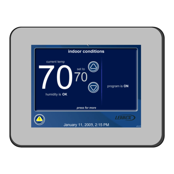
icomfortt Thermostat Features Installing icomfortt thermostat Thermostat Type Refer to the Quick Start Guide for all the information about installing the thermostat to a wall and for wiring diagrams for connecting the thermo- Electronic communicating, color display touch screen, 7−day program- stat to the system using one of a number of possible configurations. -
Page 6: Installer Setup
Installer setup − Page 1 of 8 After power is applied to the thermostat for the first time, the processor During the setup process, alerts may pop open to inform the installer checks the system for installed communicating devices, the System some item of information that affects the setup (figure 4). -
Page 7: System Settings
Number numbers etc. Dealer Email Dealer Name Figure 5. System settings Lennox Repairman The following shows the range/condition and defaults for the settings. system setting range/condition default Time and Date see Page 8 &... -
Page 8: Setting Time And Date
Installer setup − Page 3 of 8 Setting time and date Press other boxes and adjust with the arrows for all time and date information. When the date and time is correct, press save to save Use the arrows to select Time and Date; press edit (see figure 7). Press settings and return to previous settings screen. -
Page 9: Add/Remove /Modify Non−Communicating Devices
Installer setup − Page 4 of 8 Add/remove non−communicating devices /modify setup HELP From this screen (figure 9), use the yes button to access a list of non− communicating devices for installing or removing. A list similar to that non−communicating to adjust a setting, highlight it, device list shown in figure 10 will appear. -
Page 10: Modify Communicating Device Settings
Installer setup − Page 5 of 8 Modify communicating device settings setup HELP Use this screen (figure 12) to access communicating devices’ settings. to adjust a setting, highlight it, Use back to return to the previous screen or next step to go on. then press edit Equipment Name setup... - Page 11 Installer setup − Page 6 of 8 If you select reset and then confirm, the highlighted device will be reset After a reset, the device which had its settings reset to to its factory setting. You would see a screen similar to figure 14, but ref- XP19−060−230−06 default will display in the system devices screen in red 5809K00015...
-
Page 12: Indoor Air Quality Controls
Installer setup − Page 7 of 8 Indoor air quality controls setup tests equipment HELP An example of installing UV Light is shown in figure 10, Page 9. (to adjust a device, highlight system devices it, then press edit) XP19−060−230−06 To turn on humidification or dehumidification controls, in addition to 5809K00015 the setup described on Page 9, work from either the setup tab or the... - Page 13 Installer setup − Page 8 of 8 HUMIDIFICATION modes setup tests equipment HELP BASIC & PRECISION these modes allow user control of RH between (to adjust a setting, highlight 15 and 45%. These conditions must be met for either mode to operate: SYSTEM it, then press edit) humidification mode has been enabled, and...
-
Page 14: Tests
Tests − Page 1 of 1 The tests feature is not available until after setup has been completed When the tests screen opens, TEST ALL will be highlighted (but not yet once. After you press next step in the final setup screen, the Select selected). - Page 15 Tests − Page 1 of 1 After the tests have been started, the screen will describe which test is After pressing done, the Testing finished" screen will appear (see figure running (see figure 20). After concluding that the results are the desired 21).
- Page 16 Equipment − Page 1 of 1 This feature allows the installer to edit details of devices in the system setup tests equipment HELP without having to re−run the setup program. The following appears after the equipment tab has been selected SYSTEM (to adjust a setting, highlight press start button below to edit details of devices in...
-
Page 17: Diagnostics
Diagnostics − Page 1 of 1 If you need to run diagnostics to analyze the system, press the diagnos- select type of device to run tics tab. The Select device to run diagnostics" screen (figure 24) will diagnostics on run diagnostics on: open. -
Page 18: Alerts
Alerts − Page 1 of 4 As described earlier on Page 6, alerts may pop up on the screen during The first alert will be displayed in the Device alert" screen (figure 27), in order of: setup. To view alerts otherwise, press the alerts tab. Up to 10 alerts are stored for recall by the technician. - Page 19 Alerts − Page 2 of 4 Clearing alerts alert description set time for next reminder A critical alert (red icon) identifies a system or device issue that can pre- disabled vent the system from working properly or at all, and if allowed to run, ALERT 1 of 5 could cause damage to the system.
- Page 20 Alerts − Page 3 of 4 Using custom time" set time for next reminder alert description Use Setting custom time" screen (figure 30) to set an exact date and 1 day time for the reminder to appear. Press in one of the boxes to highlight it ALERT 1 of 5 1 week and use the up/down arrows to change the value in that box.
- Page 21 Alerts − Page 4 of 4 View cleared alerts A history of cleared alerts allows the installer to review the cleared alerts. If no alert or only one alert is present in the history of cleared alerts, only This information can help diagnose problems. Use the arrows to (figure the back button appears.
-
Page 22: Access Installer Program From User Home Screen
To access the installer program after the unit has been placed in opera- Figure 36, Qualified Lennox equipment installer warning" screen ap- tion and the user home screen is displayed, press the Lennox" logo and pears; press yes to proceed (no returns the home screen). -
Page 23: Reconfiguring A System
Reconfiguring a system − Page 1 of 2 To begin reconfiguring a system, press the setup tab. Press confirm to continue system configuration; the screen will change to the system discovery screen. The Start system configuration" screen (figure 37) appears; press start to proceed. - Page 24 Reconfiguring a system − Page 2 of 2 While reconfiguring, the thermostat will have retained settings from the Figure 41 lists all communicating devices found and gives you an oppor- previous configuration. If a device has been replaced and re−configura- tunity to review the reconfigured devices.
-
Page 25: Editable Parameters Table (User And Installer)
Daylight Saving Time Enabled Enabled, Disabled Circulate Fan − Percentage of Time ON 15 to 45% Dealer Contact Information – Name Lennox (Typewriter input screen) Dealer Contact Information – Address (Typewriter input screen) Dealer Contact Information – Phone 1−800−9−LENNOX (Typewriter input screen) Dealer Contact Information –... - Page 26 Parameter Name: Default Parameter Value Setting Increment 1st Stage Differential 0.5ºF 0.5 to 3ºF .5ºF 2nd Stage Differential 1.5ºF 0.5 to 8ºF .5ºF 3rd Stage Differential 2.0ºF 0.5 to 8ºF .5ºF 4th Stage Differential 2.5ºF 0.5 to 8ºF .5ºF 5th Stage Differential 3.0ºF 0.5 to 8ºF .5ºF...
- Page 27 Parameter Name: Default Parameter Value Setting Increment AIR HANDLER Equipment Name Air Handler (Typewriter input screen) Electric Heating Airflow 5CFM nnnn CFM Low Cooling Airflow 5CFM NOTE: CFM Default and Values Settings are dependent on the tonnage of the unit SEE NOTE −.
- Page 28 Value Default Min. Max. Incr. Parameter Name Dependency Note FURNACE Heating indoor blower OFF delay DIP SW None DIP switch setting in Non−comm. Heating indoor blower ON delay None 45 sec fixed in Non−Comm. IFC Cooling indoor blower OFF delay Outdoor Unit present Not used on Non Com.
- Page 29 Value Default Min. Max. Incr. Parameter Name Parameter Name Dependency Dependency Note Note Cooling Airflow Setting High Cooling Airflow OU tons (OUNC) * Min CFM Max CFM Outdoor Unit present 1/2 HP blower (CFM @ 100% cool) 400CFM Min CFM Max CFM 1 HP blower Low Cooling Airflow...
-
Page 30: User Settings
Daylight Saving Time Enabled Enabled, Disabled Circulate Fan − Percentage of Time ON 15 to 45% Dealer Contact Information – Name Lennox (Typewriter input screen) Dealer Contact Information – Address (Typewriter input screen) Dealer Contact Information – Phone 1−800−9−LENNOX (Typewriter input screen) Dealer Contact Information –... -
Page 31: Alarm Codes And Descriptions
Action required to Clear/Recover Unknown Device Detected − DEVICE2 Reconfigure the system. Press and hold Lennox Logo, press setup tab, press start, and press confirm. If still persists, then check all DEVICE connections to make sure they are icomfort compatible. - Page 32 Alarm Codes and Troubleshooting Alarm ID Message Name Action required to Clear/Recover Control Hardware Problem Hardware problem on the control board. Cycle power on control. Replace if problem prevents service and is persistent. Control Internal Communication Problem Hardware problem on the control board. Cycle power on control. Replace if problem prevents service and is persistent.
-
Page 33: Alarm Codes
Alarm Codes and Troubleshooting Alarm ID Message Name Action required to Clear/Recover Flame Out of Sequence − Still Present Shut off gas, check for gas valve leak. Primary Limit Switch Open Check firing rate on furnace, blockage in heater, and air flow. Discharge Air Temperature High Check temperature rise, air flow and input rate. - Page 34 Alarm Codes and Troubleshooting Alarm ID Message Name Action required to Clear/Recover Indoor/Outdoor Unit Capacity Mismatch Incorrect indoor/outdoor capacity code selected. Check for proper configuring in installation instructions. Alarm is just a warning. The system will operate, but might not meet efficiency and capacity parameters and alarm would clear when commissioning is exited.
- Page 35 Alarm Codes and Troubleshooting Alarm ID Message Name Action required to Clear/Recover Open Low Pressure Switch Remove any blockages or restrictions from indoor coils and/or fans. Check refrigerant charge and system operation. Low Pressure Switch Strikes Lockout Check system charge using approach and sub cooling temperatures. Reset by putting outdoor board in test mode or resetting low voltage power.
-
Page 36: Wiring Diagrams
Wiring Diagrams − Communicating Systems icomfortt DAS NOTE − The discharge air sensor FURNACE (IFC) OR AIR HANDLER (AHC) is intended to be mounted downstream OPTIONAL DIS- of the heat exchanger and air condi- CHARGE AIR SEN- tioning coil. It must be placed in free SOR (SEE DAS airflow, where other accessories (such NOTE) - Page 37 Wiring Diagrams − Communicating Indoor/non−Communicating Outdoor Systems icomfortt AIR HANDLER (AHC) icomfortt FURNACE (IFC) OR AIR HANDLER (AHC) OPTIONAL DIS- OPTIONAL DIS- OPTIONAL OUT- CHARGE AIR SEN- OPTIONAL OUT- CHARGE AIR SEN- DOOR AIR SENSOR SOR (SEE DAS SOR (SEE DAS DOOR AIR SENSOR (SEE OAS NOTE NOTE Page 36)
- Page 38 1500ft. Wire gauge of NOTE: 24V UV LIGHT RSBus wire is 18. APPLICATIONS Neither icomfort furnace nor icomfort air handler transformer will have adequate VA to power 24V UV light applications. An additional transformer for UV light applications is required.
- Page 39 Optional Accessories for use with any icomfortt system icomfortt icomfortt icomfortt FURNACE OR FURNACE OR OUTDOOR AIR AIR HANDLER AIR HANDLER HEPA BYPASS FIL- CONDITIONING OR TER X2680 HEPA HEAT PUMP UNIT INTERLOCK KIT PASS INDOOR BLOWER MOTOR COMMON WIRE THROUGH CURRENT LOOP.