Advertisement
Quick Links
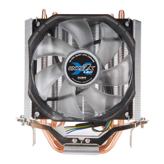
User's Manual
Intel Socket 1155 / 1156 / 1366 / 775 CPU
AMD Socket AM3 / AM2+ / AM2 CPU
To ensure safe and easy installation,
please read the following precautions
www.ZALMAN.com
CNPS7X
Core i7 Extreme
Core i7
Core i5
Core i3
Core 2 Extreme
Core 2 Quad
Core 2 Duo
Dual Core Pentium
Pentium D
Pentium 4
Celeron D
Phenom II
Phenom
Athlon II
Athlon X2
Athlon FX
Athlon
Opteron
Dual-Core Opteron
Sempron
V 1.1
Advertisement

Related Manuals for ZALMAN CNPS7X


Summary of Contents for ZALMAN CNPS7X
- Page 1 User’s Manual CNPS7X Intel Socket 1155 / 1156 / 1366 / 775 CPU Core i7 Extreme Core i7 Core i5 Core i3 Core 2 Extreme Core 2 Quad Core 2 Duo Dual Core Pentium Pentium D Pentium 4 Celeron D...
-
Page 2: Specifications
Product design and specifications may be revised to improve quality and performance. Enable PWM function in BIOS settings after installation. Disclaimer) Zalman Tech Co., Ltd. is not responsible for any damages due to external causes, including but not limited to, improper use, problems with electrical power, accident, neglect, alteration, repair, improper installation, or improper testing. -
Page 3: Installation Requirements
3. Components Cooler A-type Clip Support B-type Clip Support & Pushpins & Pushpins [For LGA 1155 / 1156 / 775] [For LGA 1366] User’s Manual Thermal Grease Resistor Cable 4. Installation Requirements 1) Space Requirements The cooler’s installation requires an unobstructed space of 135㎜ (width), 100㎜(length), and 140㎜(height), with the CPU as a central reference point. -
Page 4: Installation
3) Cooler Orientation As shown in the diagram below, it is recommended that the cooler be installed so that air flows from the cooler toward the enclosure’s rear exhaust fan to be released. ※ Recommended cooler orientation may differ according to the motherboard model. - Page 5 ①-ⓑ B-type Clip Support Installation(Socket 1366) Fasten the B-type Clip Support to the motherboard with pushpins. ② Clear off any particles or residue from the CPU’ s surface. Then spread a thorough layer of Thermal Grease on the CPU and the base of the cooler.
- Page 6 When reassembling the bolt, be sure to assemble only half way of the total length. ④ Install the cooler on the Clip support as shown in the picture and connect the lug slot of the clip on to the lug on the clip support. Then fasten the bolts on each side a few turns at a time.
- Page 7 AMD Socket AM3 / AM2+ / AM2 Installation ① Clear off any particles or residue from the CPU’s surface. Then spread a thorough layer of Thermal Grease on the CPU and the base of the cooler. ② Completely unfasten the 2 bolts already assembled on the clip and adjust the position to fit the AMD socket.
- Page 8 ④ Connect the cooler’s 4-pin connector to the motherboard’s CPU Fan header. Fan RPM resistor <Performance Mode> <Low-Noise Mode> .COM...