Planet FGSW-2620VM User Manual
24-port gigabit tp/sfp managed switches
Hide thumbs
Also See for FGSW-2620VM:
- User manual (194 pages) ,
- Specification (3 pages) ,
- Quick installation manual (2 pages)
Table of Contents
Advertisement
FGSW-2620VM
24-Port 10/100Mbps + 2 Gigabit TP/SFP
Layer 2 Managed Switch
FGSW-2620PVM
24-Port 10/100Mbps + 2 Gigabit TP/SFP
Managed PoE Switch
FGSW-2620VMP4
24-Port 10/100Mbps + 2 Gigabit TP/SFP
Managed PoE Switch – 380W
FGSW-2612PVM
24-Port 10/100Mbps + 2 Gigabit TP/SFP
With 12-Port PoE Managed Switch
FGSW-2624SF
24 100Base-FX SFP Slots + 2 Gigabit TP/SFP
Managed Ethernet Switch
User's Manual of FGSW-2620VM
User's Manual
Advertisement
Table of Contents

Related Manuals for Planet FGSW-2620VM


Summary of Contents for Planet FGSW-2620VM
- Page 1 User’s Manual of FGSW-2620VM User’s Manual FGSW-2620VM 24-Port 10/100Mbps + 2 Gigabit TP/SFP Layer 2 Managed Switch FGSW-2620PVM 24-Port 10/100Mbps + 2 Gigabit TP/SFP Managed PoE Switch FGSW-2620VMP4 24-Port 10/100Mbps + 2 Gigabit TP/SFP Managed PoE Switch – 380W FGSW-2612PVM...
-
Page 2: Fcc Warning
PLANET is a registered trademark of PLANET Technology Corp. All other trademarks belong to their respective owners. Disclaimer PLANET Technology does not warrant that the hardware will work properly in all environments and applications, and makes no warranty and representation, either implied or expressed, with respect to the quality, performance, merchantability, or fitness for a particular purpose. -
Page 3: Table Of Contents
3.1 Requirements ............................34 3.2 Management Access Overview ......................35 3.3 Web Management..........................36 3.4 SNMP-Based Network Management ....................37 3.5 Administration Console (FGSW-2620VM doesn’t support) ............37 3.6 Protocols.............................. 39 3.6.1 Virtual Terminal Protocols ......................39 3.6.2 SNMP Protocol .......................... 39 3.6.3 Management Architecture ...................... - Page 4 User’s Manual of FGSW-Series 4.2.1.2 Misc Config ........................46 4.2.2 IP Configuration ......................... 48 4.2.3 SNMP Configuration........................50 4.2.3.1 SNMP Overview......................... 50 4.2.3.2 System Options........................51 4.2.3.3 Community Strings......................52 4.2.3.4 Trap Managers........................53 4.2.4 Firmware Upgrade........................54 4.2.4.1 TFTP Firmware Upgrade ....................54 4.2.4.2 HTTP Firmware Upgrade....................
- Page 5 User’s Manual of FGSW-Series 4.6 Trunking ............................... 91 4.6.1 Aggregator setting ........................92 4.6.2 Aggregator Information......................93 4.6.3 State Activity ..........................97 4.7 Forwarding and Filtering ........................99 4.7.1 Dynamic MAC Table........................99 4.7.2 Static MAC Table........................100 4.7.3 MAC Filtering ........................... 101 4.8 IGMP Snooping ..........................
- Page 6 User’s Manual of FGSW-Series 6.1 Operation Notice ..........................135 6.2 System Commands........................... 136 show running-config ........................136 copy running-config startup-config....................136 erase startup-config ........................136 clear arp ............................136 show arp............................136 ping............................... 136 6.3 Switch Static Configuration ......................137 6.3.1 Port Configuration and show status ..................
- Page 7 User’s Manual of FGSW-Series 6.5.2 VLAN Mode: Port-based......................145 show vlan mode ........................... 145 vlan mode............................. 145 6.5.3 Advanced 802.1Q VLAN Configuration................... 146 show vlan mode ........................... 146 vlan mode............................. 146 vlan add............................146 no vlan............................147 show vlan ............................. 147 show vlan static..........................
- Page 8 User’s Manual of FGSW-Series copy tftp firmware......................... 154 6.7.6 Restore Configure File......................154 copy tftp <running-config | flash> ....................154 6.7.7 Backup Configure File ......................154 copy <running-config | flash> tftp ....................154 6.8 MAC limit............................155 mac-limit ............................155 no mac-limit..........................
- Page 9 User’s Manual of FGSW-Series spanning-tree maximum-age ....................... 161 spanning-tree priority ........................162 spanning-tree port path-cost ......................162 spanning-tree port priority ......................162 show spanning-tree........................162 show spanning-tree port....................... 162 [no] spanning-tree debug ......................163 spanning-tree protocol-version ....................163 [no] spanning-tree port mcheck ....................163 [no] spanning-tree port edge-port ....................
- Page 10 User’s Manual of FGSW-Series show igmp ............................ 168 igmp clear_statistics........................168 6.15 802.1x Protocol..........................169 dot1x............................. 169 radius-server host ........................169 radius-server key.......................... 169 radius-server nas ......................... 169 show radius-server........................169 dot1x timeout quiet-period......................170 dot1x timeout tx-period......................... 170 dot1x timeout supplicant ......................170 dot1x timeout radius-server......................
- Page 11 User’s Manual of FGSW-Series show poe status ........................... 177 6.18.2 Configure PoE Over Temperature Protection ............... 178 poe temperature-protection enable....................178 6.18.3 Configure PoE -- System....................... 179 poe limit-mode..........................179 6.18.4 Configure PoE -- Port ......................180 poe enable ........................... 180 poe priority............................
-
Page 12: Introduction
User’s Manual of FGSW-Series 1. Introduction The PLANET Layer 2 Managed Switch series - FGSW-2620VM, FGSW-2624SF and Managed PoE Switch series - FGSW-2620PVM, FGSW-2620VMP4, FGSW-2612PVM and are multiple 10/100Mbps ports Ethernet Switched with Gigabit TP/SFP fiber optical combo connective ability and robust layer 2 features; the description of these models are shown as... -
Page 13: Product Description
Not only for catering to the need of easy WEB-based management but also the centralized SNMP application to monitor the status of Switch and traffic per port, PLANET releases the cost-effective Managed Switch. The key features are as below: 380 Watts Full PoE Power (FGSW-2620VMP4) WEB / SSL / Telnet 802.1Q / Q-in-Q VLAN... -
Page 14: How To Use This Manual
User’s Manual of FGSW-Series 1.3 How to Use This Manual This User Manual is structured as follows: Section 2, INSTALLATION The section explains the functions of the Switch and how to physically install the Managed Switch. Section 3, SWITCH MANAGEMENT The section contains the information about the software function of the Managed Switch. -
Page 15: Product Features
User’s Manual of FGSW-Series 1.4 Product Features Physical Port FGSW-2620VM 24-Port 10/100Base-TX RJ-45 interfaces 2-Port Gigabit TP/SFP combo interfaces Reset button for system management FGSW-2620PVM / FGSW-2620VMP4 / FGSW-2612PVM 24-Port 10/100Base-TX RJ-45 with PoE Injector 2-Port Gigabit TP/SFP combo interfaces... - Page 16 • Web switch management • Telnet Command Line Interface • SNMP v1, v2c switch management • Console local management (Not include FGSW-2620VM) SNMP Trap for alarm notification of events Four RMON groups 1, 2, 3, 9 (history, statistics, alarms, and events)
-
Page 17: Product Specification
User’s Manual of FGSW-Series 1.5 Product Specification Product FGSW-2620VM FGSW-2624SF Hardware Specification Version 2 Version 4 Hardware Version 24 10/ 100Base-TX RJ-45 10/100Mbps Copper Ports Auto-MDI/MDI-X ports 24 SFP slots 100Mbps Fiber Ports 2 10/100/1000Base-T RJ-45 port 1000Mbps Copper Ports... - Page 18 User’s Manual of FGSW-Series Flow Control disable / enable. Bandwidth control and broadcast storm filter on each port. Display each port’s speed duplex mode, link status, Flow control status and Auto Port Status negotiation status Port-Based VLAN, up to 26 VLAN groups VLAN IEEE 802.1q Tagged Based VLAN , 4K VLAN ID, up to 256 VLAN groups IEEE 802.1D Spanning Tree...
- Page 19 User’s Manual of FGSW-Series IEEE 802.1x Port Authentication Network Control • 50 / 125µm or 62.5 / 125µm multi-mode fiber cable: - 100Base-FX : up to 2km - 1000Base-SX: up to 220 / 550m Cable-Fiber-optic cable • 9 / 125µm single-mode cable, provides long distance for : - 100Base-FX: up to 10/40/60km (very on fiber transceiver or SFP module) - 1000Base-LX / ZX: 10 / 15 / 20 / 30 / 40 / 50 / 60 / 70 / 120km (very on fiber transceiver or SFP module)
- Page 20 User’s Manual of FGSW-Series Standard: 0 ~ 50 Degree C Operating Temperature 20% to 95% (Non-condensing) Operating Humidity -10 Degree C ~ 85 Degree C Storage Temperature Layer 2 Functions Console, Telnet, Web Browser, SNMP v1, v2c Management Interface Port disable / enable. Auto-negotiation 10/100Mbps full and half duplex mode selection.
- Page 21 User’s Manual of FGSW-Series Per Port 48V DC, 350mA . Max. 15.4 watts PoE Power output 1/2(+), 3/6(-) Power Pin Assignment 110Watts 190Watts 380Watts PoE Power Budget Max. number of Class2 PD Max. number of Class 3 PD Standards Conformance FCC Part 15 Class A, CE FCC Part 15 Class A, CE Safety...
-
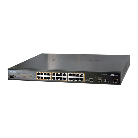
Page 22: Installation
The unit front panel provides a simple interface monitoring the switch. Figure 2-1-1 to 2-1-5 shows the front panel of the Managed Switches. FGSW-2620VM Front Panel Figure 2-1-1: FGSW-2620VM front panel FGSW-2620PVM Front Panel Figure 2-1-2: FGSW-2620PVM Switch front panel FGSW-2620VMP4 Front Panel Figure 2-1-3: FGSW-2620VMP4 Switch front panel... - Page 23 Port-25, Port-26: 1000Base-SX/LX mini-GBIC slot, SFP (Small Factor Pluggable) transceiver module: From 550 meters (Multi-mode fiber), up to 10/30/50/70/120 kilometers (Single-mode fiber). ■ Console Port (not include FGSW-2620VM) The console port is a DB9, RS-232 male serial port connector. It is an interface for connecting a terminal directly.
-
Page 24: Led Indications
2.1.2 LED Indications The front panel LEDs indicates instant status of port links, data activity and system power; helps monitor and troubleshoot when needed. FGSW-2620VM LED indication Figure 2-1-6: FGSW-2620VM LED panel System Color Function Lights to indicate that the Switch has power. - Page 25 User’s Manual of FGSW-Series FGSW-2620PVM LED indication Figure 2-1-7: FGSW-2620PVM LED panel System Color Function Lights to indicate that the Switch has power. Green Per 10/100Base-TX, PoE interfaces (Port-1 to Por-24) Color Function Lights: To indicate the link through that port is successfully established. LNK/ACT Green Blink: To indicate that the Switch is actively sending or receiving data over that port.
- Page 26 User’s Manual of FGSW-Series FGSW-2620VMP4 LED indication Figure 2-1-8: FGSW-2620VMP4 LED panel System Color Function Lights to indicate that the Switch has power. Green Lights to indicate that the FAN#1 has stopped. FAN1 Green Lights to indicate that the FAN#2 has stopped. FAN2 Green Lights to indicate that the FAN#3 has stopped.
- Page 27 User’s Manual of FGSW-2620VM FGSW-2612PVM LED indication Figure 2-1-9: FGSW-2612PVM LED panel System Color Function Lights to indicate that the Switch has power. Green Per 10/100Base-TX, PoE interfaces (Port-1 to Por-24) Color Function Lights: To indicate the link through that port is successfully established.
- Page 28 The Switch will back to the factory default mode; the entire configuration will be erased. The 2 Gigabit TP/SFP combo ports are shared with port 25/26 of FGSW-2620VM / FGSW-2620PVM / FGSW-2620VMP4 / FGSW-2612PVM / FGSW-2624SF either of them can operate at the same time.
-
Page 29: Switch Rear Panel
50-60Hz. Figure 2-1-11 Figure 2-1-15 shows the rear panel of the Switch. FGSW-2620VM Rear Panel Figure 2-1-11: FGSW-2620VM rear panel. FGSW-2620PVM Rear Panel Figure 2-1-12: FGSW-2620PVM Switch rear panel FGSW-2620VMP4 Rear Panel Figure 2-1-13: FGSW-2620PVM Switch rear panel FGSW-2612PVM Rear Panel... -
Page 30: Install The Switch
User’s Manual of FGSW-Series 2.2 Install the Switch This section describes how to install the Managed Switch and make connections to it. Please read the following topics and perform the procedures in the order being presented. 2.2.1 Desktop Installation To install the Managed Switch on desktop or shelf, please follows these steps: Attach the rubber feet to the recessed areas on the bottom of the Managed Switch. -
Page 31: Rack Mounting
User’s Manual of FGSW-Series 2.2.2 Rack Mounting To install the Managed Switch in a 19-inch standard rack, please follows the instructions described below. Place the Managed Switch on a hard flat surface, with the front panel positioned towards the front side. Step1: Attach the rack-mount bracket to each side of the Managed Switch with supplied screws attached to the package. -
Page 32: Installing The Sfp Transceiver
Figure 2-2-4: Plug-in the SFP transceiver Approved PLANET SFP Transceivers PLANET Managed switches supports both single mode and multi mode SFP transceiver. The following list of approved PLANET SFP transceivers is correct at the time of publication: 1000Base-SX/LX SFP transceiver: MGB-SX SFP (1000BASE-SX SFP transceiver –... - Page 33 User’s Manual of FGSW-Series To connect to 1000Base-LX SFP transceiver, use the single-mode fiber cable-with one side must be male duplex LC connector type. Connect the fiber cable Attach the duplex LC connector on the network cable into the SFP transceiver. Connect the other end of the cable to a device –...
-
Page 34: Switch Management
• Network cables - Use standard network (UTP) cables with RJ45 connectors. Above Workstation installed with WEB Browser and JAVA runtime environment Plug-in Serial Port connect (Not include FGSW-2620VM) • Above PC with COM Port (DB-9 / RS-232) or USB-to-RS-232 converter... -
Page 35: Management Access Overview
User’s Manual of FGSW-Series 3.2 Management Access Overview The Managed Switch gives you the flexibility to access and manage it using any or all of the following methods: Web browser interface An external SNMP-based network management application An administration console The administration console and Web browser interface support are embedded in the Managed Switch software and are available for immediate use. -
Page 36: Web Management
User’s Manual of FGSW-Series 3.3 Web Management The Managed Switch offers management features that allow users to manage the Managed Switch from anywhere on the network through a standard browser such as Microsoft Internet Explorer. After you set up your IP address for the switch, you can access the Managed Switch's Web interface applications directly in your Web browser by entering the IP address of the Managed Switch. -
Page 37: Snmp-Based Network Management
Switch are public. Figure 3-4-1: SNMP management 3.5 Administration Console (FGSW-2620VM doesn’t support) The administration console is an internal, character-oriented, and command line user interface for performing system administration such as displaying statistics or changing option settings. Using this method, you can view the administration console from a terminal, personal computer, Apple Macintosh, or workstation connected to the switch's console (serial) port. - Page 38 User’s Manual of FGSW-Series Direct Access Direct access to the administration console is achieved by directly connecting a terminal or a PC equipped with a terminal-emulation program (such as HyperTerminal) to the Managed Switch console (serial) port. When using this management method, a straight DB9 RS-232 cable is required to connect the switch to the PC. After making this connection, configure the terminal-emulation program to use the following parameters: The default parameters are: 57600 bps...
-
Page 39: Protocols
User’s Manual of FGSW-Series 3.6 Protocols The Managed Switch supports the following protocols: Virtual terminal protocols, such as Telnet Simple Network Management Protocol (SNMP) 3.6.1 Virtual Terminal Protocols A virtual terminal protocol is a software program, such as Telnet, that allows you to establish a management session from a Macintosh, a PC, or a UNIX workstation. -
Page 40: Web-Based Management
User’s Manual of FGSW-Series 4. Web-Based Management This section introduces the configuration and functions of the Web-Based management. 4.1 About Web-based Management The Managed Switch offers management features that allow users to manage the Managed Switch from anywhere on the network through a standard browser such as Microsoft Internet Explorer. -
Page 41: Requirements
User’s Manual of FGSW-Series 4.1.1 Requirements • Workstations of subscribers running Windows 98/ME, NT4.0, 2000/2003/XP, MAC OS9 or later, Linux, UNIX or other platform compatible with TCP/IP protocols. • Workstation installed with Ethernet NIC (Network Card). • Ethernet Port connect Network cables - Use standard network (UTP) cables with RJ45 connectors. - Page 42 The WEB configuration of FGSW-2620PVM / FGSW-2620VMP4 / FGSW-2612PVM / FGSW-2624SF is the same with FGSW-2620VM except PoE feature, the FGSW-2620VM , FGSW-2620VMP4 and FGSW-2612PVM will be the same example to describe how to configure switch and also, will describe PoE configuration in additional.
-
Page 43: Main Web Page
User’s Manual of FGSW-Series 4.1.3 Main WEB PAGE The Managed Switch provides a Web-based browser interface for configuring and managing it. This interface allows you to access the Managed Switch using the Web browser of your choice. This chapter describes how to use the Managed Switch’s Web browser interface to configure and manage it. -
Page 44: System
User’s Manual of FGSW-Series The PoE Ports panel display is for FGSW-2620PVM / FGSW-2620VMP4 / FGSW-2612PVM only. Main Menu Using the onboard web agent, you can define system parameters, manage and control the Managed Switch, and all its ports, or monitor network conditions. Via the Web-Management, the administrator can setup the Managed Switch by select the functions those listed in the Main Function. -
Page 45: System Information
User’s Manual of FGSW-Series 4.2.1 System Information In System information, it has two parts of setting – Basic and Misc Config. We will describe the configure detail in following. 4.2.1.1 Basic The Basic System Info page provides information for the current device information. Basic System Info page helps a switch administrator to identify the model name, firmware / hardware version and MAC address. -
Page 46: Misc Config
User’s Manual of FGSW-Series 4.2.1.2 Misc Config Choose Misc Config from System Information of Managed Switch, the screen in Figure 4-2-2 appears. Figure 4-2-2: Switch Misc Config screenshot The page includes the following fields: Object Description Type the number of seconds that an inactive MAC address remains in the MAC Address Age-out switch's address table. - Page 47 User’s Manual of FGSW-Series individual ports. The threshold is the percentage of the port's total bandwidth Mode used by broadcast traffic. When broadcast traffic for a port rises above the threshold you set, broadcast storm control becomes active. The valid threshold values are 1/2, 1/4, 1/8, 1/16 and OFF. Default is “OFF”.
-
Page 48: Ip Configuration
User’s Manual of FGSW-Series 4.2.2 IP Configuration The Managed Switch is a network device which needs to be assigned an IP address for being identified on the network. Users have to decide a means of assigning IP address to the Managed Switch. IP address overview What is an IP address? Each device (such as a computer) which participates in an IP network needs a unique "address"... - Page 49 User’s Manual of FGSW-Series The page includes the following fields: Object Description Enable or disable the DHCP client function. When DHCP function is enabled, the Managed Switch will be assigned an IP address from the network DHCP server. The default IP address will be replaced DHCP by the assigned IP address on DHCP server.
-
Page 50: Snmp Configuration
User’s Manual of FGSW-Series 4.2.3 SNMP Configuration 4.2.3.1 SNMP Overview The Simple Network Management Protocol (SNMP) is an application layer protocol that facilitates the exchange of management information between network devices. It is part of the Transmission Control Protocol/Internet Protocol (TCP/IP) protocol suite. -
Page 51: System Options
User’s Manual of FGSW-Series agents and NMSs. SNMP is the Internet community's de facto standard management protocol. SNMP Operations SNMP itself is a simple request/response protocol. NMSs can send multiple requests without receiving a response. Get -- Allows the NMS to retrieve an object instance from the agent. 。... -
Page 52: Community Strings
User’s Manual of FGSW-Series • The physical location of this node (e.g., telephone closet, 3rd floor). System Location The allowed string length is 0 to 255, and the allowed content is the ASCII characters from 32 to 126. • The textual identification of the contact person for this managed node, together System Contact with information on how to contact this person. -
Page 53: Trap Managers
User’s Manual of FGSW-Series 4.2.3.4 Trap Managers A trap manager is a management station that receives the trap messages generated by the switch. If no trap manager is defined, no traps will be issued. To define a management station as a trap manager, assign an IP address, enter the SNMP community strings, and select the SNMP trap version. -
Page 54: Firmware Upgrade
User’s Manual of FGSW-Series 4.2.4 Firmware Upgrade It provides the functions allowing the user to update the switch firmware via the Trivial File Transfer Protocol (TFTP) server. Before updating, make sure the TFTP server is ready and the firmware image is located on the TFTP server. 4.2.4.1 TFTP Firmware Upgrade The Firmware Upgrade page provides the functions to allow a user to update the Managed Switch firmware from the TFTP server in the network. -
Page 55: Http Firmware Upgrade
User’s Manual of FGSW-Series 4.2.4.2 HTTP Firmware Upgrade The HTTP Firmware Upgrade page contains fields for downloading system image files from the Local File browser to the device. The Web Firmware Upgrade screen in Figure 4-2-9 appears. Figure 4-2-9: HTTP Firmware Upgrade interface To open Firmware Upgrade screen perform the folling: Click System ->... -
Page 56: Configuration Backup
User’s Manual of FGSW-Series 4.2.5 Configuration Backup 4.2.5.1 TFTP Restore Configuration You can restore a previous backup configuration from the TFTP server to recover the settings. Before doing that, you must locate the image file on the TFTP server first and the Managed Switch will download back the flash image. Figure 4-2-10: Configuration Restore interface The page includes the following fields: Object... -
Page 57: Tftp Backup Configuration
User’s Manual of FGSW-Series 4.2.5.2 TFTP Backup Configuration You can back up the current configuration from flash ROM to the TFTP server for the purpose of recovering the configuration later. It helps you to avoid wasting time on configuring the settings by backing up the configuration. Figure 4-2-11: Configuration Backup interface The page includes the following fields: Object... -
Page 58: Factory Default
User’s Manual of FGSW-Series 4.2.6 Factory Default Default Reset switch to default configuration. Click to reset all configurations to the default value. Figure 4-2-12: Factory Default interface 4.2.7 System Reboot Reboot Reboot the switch in software reset. Click to reboot the system. Figure 4-2-13 : System Reboot interface... -
Page 59: Port Configuration
User’s Manual of FGSW-Series 4.3 Port Configuration 4.3.1 Port Control In Port control you can configure the settings of each port to control the connection parameters, and the status of each port is listed beneath. Figure 4-3-1: Port Control interface The page includes the following fields: Object Description... - Page 60 User’s Manual of FGSW-Series Port-1 ~ Port-24, supports by-port ingress and egress rate control. For example, assume port 1 is 10Mbps, users can set its effective egress rate at 1Mbps and ingress rate at 500Kbps. Device will perform flow control or backpressure to confine the ingress rate to meet the specified rate.
-
Page 61: Port Status
User’s Manual of FGSW-Series 4.3.2 Port Status This page displays current port configurations and operating status - it is a ports’ configurations summary table. Via the summary table, you can know status of each port clear at a glance, like Port Link Up/Link Down status, negotiation, Link Speed, Rate Control, Duplex mode and Flow Control. -
Page 62: Port Statistics
User’s Manual of FGSW-Series 4.3.3 Port Statistics The following chart provides the current statistic information which displays the real-time packet transfer status for each port. The user might use the information to plan and implement the network, or check and find the problem when the collision or heavy traffic occurs. -
Page 63: Port Sniffer
User’s Manual of FGSW-Series The counts of receiving good packets (including undersize [less than 64 octets], Rx Bad Packet: oversize, CRC error, fragments and jabbers) via this port. The aborted packet while transmitting. Tx Abort Packet: The counts of collision packet. Packet Collision: The counts of dropped packet. - Page 64 User’s Manual of FGSW-Series Figure 4-3-5: Port Sniffer interface The page includes the following fields: Object Description Select a sniffer mode: • Disable • Rx Sniffer Type: • Tx • Both It’ means Analysis port can be used to see the traffic on another port you want to Analysis (Monitoring) Port: monitor.
-
Page 65: Vlan Configuration
User’s Manual of FGSW-Series 4.4 VLAN configuration 4.4.1 VLAN Overview A Virtual Local Area Network (VLAN) is a network topology configured according to a logical scheme rather than the physical layout. VLAN can be used to combine any collection of LAN segments into an autonomous user group that appears as a single LAN. - Page 66 User’s Manual of FGSW-Series that are members of the VLAN. Any port can be configured as either tagging or untagging. The untagging feature of IEEE 802.1Q VLAN allows VLAN to work with legacy switches that don't recognize VLAN tags in packet headers. The tagging feature allows VLAN to span multiple 802.1Q-compliant switches through a single physical connection and allows Spanning Tree to be enabled on all ports and work normally.
- Page 67 User’s Manual of FGSW-Series Adding an IEEE802.1Q Tag Original Ethernet Dest. Addr. Src. Addr. Length/E. type Data Old CRC Dest. Addr. Src. Addr. Length/E. type Data New CRC E. type New Tagged Packet Priority VLAN ID Port VLAN ID Packets that are tagged (are carrying the 802.1Q VID information) can be transmitted from one 802.1Q compliant network device to another with the VLAN information intact.
-
Page 68: Static Vlan Configuration
User’s Manual of FGSW-Series group settings. VLAN settings will automatically change in conjunction with the change of the port link aggregation group settings. 4.4.2 Static VLAN Configuration A Virtual LAN (VLAN) is a logical network grouping that limits the broadcast domain. It allows you to isolate network traffic so only members of the VLAN receive traffic from the same VLAN members. -
Page 69: Port-Based Vlan
User’s Manual of FGSW-Series 4.4.3 Port-based VLAN Packets can go among only members of the same VLAN group. Note all unselected ports are treated as belonging to another single VLAN. If the port-based VLAN enabled, the VLAN-tagging is ignored. In order for an end station to send packets to different VLANs, it itself has to be either capable of tagging packets it sends with VLAN tags or attached to a VLAN-aware bridge that is capable of classifying and tagging the packet with different VLAN ID based on not only default PVID but also other information about the packet, such as the protocol. - Page 70 User’s Manual of FGSW-Series Figure 4-4-3: Static VLAN interface The page includes the following fields: Object Description Use this optional field to specify a name for the VLAN. It can be up to 16 VLAN Name alphanumeric characters long, including blanks. You can configure the ID number of the VLAN by this item.
-
Page 71: Q Vlan
User’s Manual of FGSW-Series 4.4.4 802.1Q VLAN Tagged-based VLAN is an IEEE 802.1Q specification standard. Therefore, it is possible to create a VLAN across devices from different switch venders. IEEE 802.1Q VLAN uses a technique to insert a "tag" into the Ethernet frames. Tag contains a VLAN Identifier (VID) that indicates the VLAN numbers. -
Page 72: Vlan Group Configuration
User’s Manual of FGSW-Series 4.4.4.1 VLAN Group Configuration VLAN Group Configuration Figure 4-4-4: VLAN Group Configuration interface Click the hyperlink "VLAN” \ “Static VLAN" to enter the VLAN configuration interface. Select “802.1Q” at the VLAN Operation Mode, to enable the 802.1Q VLAN function. Click Add to create a new VLAN group or Edit to management exist VLAN groups. - Page 73 User’s Manual of FGSW-Series Figure 4-4-5: VLAN Group Configuration interface Select specific port as member port and the screen in Figure 4-4-6 appears. Figure 4-4-6: 802.1Q VLAN Setting Web Page screen...
- Page 74 User’s Manual of FGSW-Series The page includes the following fields: Object Description Use this optional field to specify a name for the VLAN. It can be up to 16 VLAN Name alphanumeric characters long, including blanks. You can configure the ID number of the VLAN by this item. This field is used to add VLANs one at a time.
-
Page 75: Vlan Filter
User’s Manual of FGSW-Series 4.4.4.2 VLAN Filter 802.1Q VLAN Port Configuration This page is used for configuring the Switch port VLAN. The VLAN per Port Configuration page contains fields for managing ports that are part of a VLAN. The port default VLAN ID (PVID) is configured on the VLAN Port Configuration page. All untagged packets arriving to the device are tagged by the ports PVID. - Page 76 User’s Manual of FGSW-Series VLAN ID is 1. The VLAN ID must as same as the VLAN ID that the port belong to VLAN group, or the untagged traffic will be dropped. Ingress filtering lets frames belonging to a specific VLAN to be forwarded if the Ingress Filtering 1 port belongs to that VLAN.
-
Page 77: Q-In-Q Vlan
User’s Manual of FGSW-Series 4.4.5 Q-in-Q VLAN ■ IEEE 802.1Q Tunneling (Q-in-Q) IEEE 802.1Q Tunneling (QinQ) is designed for service providers carrying traffic for multiple customers across their networks. QinQ tunneling is used to maintain customer-specific VLAN and Layer 2 protocol configurations even when different customers use the same internal VLAN IDs. -
Page 78: Q-In-Q Port Setting
User’s Manual of FGSW-Series 4.4.5.1 Q-in-Q Port Setting The QinQ VLAN \ QinQ Port Setting screen in Figure 4-4-8 appears. Figure 4-4-8: Q-in-Q Port Setting interface The page includes the following fields: Object Description Sets the Managed Switch to QinQ mode, and allows the QinQ tunnel port to Enable: be configured. -
Page 79: Q-In-Q Tunnel Setting
User’s Manual of FGSW-Series Configures IEEE 802.1Q tunneling (QinQ) for a client access port to segregate Cancel: and preserve customer VLAN IDs for traffic crossing the service provider network. 4.4.5.2 Q-in-Q Tunnel Setting Business customers of service providers often have specific requirements for VLAN IDs and the number of VLANs to be supported. -
Page 80: Rapid Spanning Tree
User’s Manual of FGSW-Series 4.5 Rapid Spanning Tree The Rapid Spanning Tree Protocol (RSTP) is an evolution of the Spanning Tree Protocol and provides for faster spanning tree convergence after a topology change. The system also supports STP and the system will auto-detect the connected device that is running STP or RSTP protocol. - Page 81 User’s Manual of FGSW-Series The port identifier of the transmitting port. The switch sends BPDUs to communicate and construct the spanning-tree topology. All switches connected to the LAN on which the packet is transmitted will receive the BPDU. BPDUs are not directly forwarded by the switch, but the receiving switch uses the information in the frame to calculate a BPDU, and, if the topology changes, initiates a BPDU transmission.
- Page 82 User’s Manual of FGSW-Series A port transitions from one state to another as follows: From initialization (switch boot) to blocking. From blocking to listening or to disabled. From listening to learning or to disabled. From learning to forwarding or to disabled. From forwarding to disabled.
-
Page 83: Stp Parameters
User’s Manual of FGSW-Series 4.5.2 STP Parameters STP Operation Levels The Switch allows for two levels of operation: the switch level and the port level. The switch level forms a spanning tree consisting of links between one or more switches. The port level constructs a spanning tree consisting of groups of one or more ports. -
Page 84: Illustration Of Stp
User’s Manual of FGSW-Series A value used by STP to evaluate paths – 200,000-100Mbps Fast Ethernet ports Port Cost STP calculates path costs and selects the 20,000-1000Mbps Gigabit Ethernet path with the minimum cost as the active ports path. 0 - Auto Default Spanning-Tree Configuration Feature Default Value... - Page 85 User’s Manual of FGSW-Series Figure 4-5-2: Before Applying the STA Rules In this example, only the default STP values are used. Figure 4-5-3: After Applying the STA Rules...
- Page 86 User’s Manual of FGSW-Series The switch with the lowest Bridge ID (switch C) was elected the root bridge, and the ports were selected to give a high port cost between switches B and C. The two (optional) Gigabit ports (default port cost = 20,000) on switch A are connected to one (optional) Gigabit port on both switch B and C.
-
Page 87: Rstp System Configuration
User’s Manual of FGSW-Series 4.5.4 RSTP System Configuration This section provides RSTP-System Configuration from the Switch, the screen in Figure 4-5-4 appears. The user can view spanning tree information of Root Bridge. Apply The user can modify RSTP state. After modification, click Figure 4-5-4: RSTP System Configuration interface The page includes the following fields: Object... - Page 88 User’s Manual of FGSW-Series The number of seconds a port waits before changing from its Rapid Forward Delay Time Spanning-Tree Protocol learning and listening states to the forwarding state. (4-30): Enter a value between 4 through 30. Follow the rule as below to configure the MAX Age, Hello Time, and Forward Delay Time. 2 x (Forward Delay Time value –1) >...
-
Page 89: Port Configuration
User’s Manual of FGSW-Series • Maximum Age Path Cost to the Designated Root for the Root Bridge. • Hello Time Minimum time between transmissions of Configuration BPDUs. • Forward Delay Derived value of the Root Port Bridge Forward Delay parameter. 4.5.5 Port Configuration This web page provides the port configuration interface for RSTP. - Page 90 User’s Manual of FGSW-Series Decide which port should be blocked by setting its priority as the lowest. Enter a Priority: number between 0 and 240. The value of priority must be the multiple of 16. The rapid state transitions possible within RSTP are dependent upon whether the port concerned can only be connected to exactly another bridge (i.e.
-
Page 91: Trunking
User’s Manual of FGSW-Series 4.6 Trunking Port trunking is the combination of several ports or network cables to expand the connection speed beyond the limits of any one single port or network cable. The Managed Switch supports two types of port trunk technology: Static Trunk LACP The Link Aggregation Control Protocol (LACP) provides a standardized means for exchanging information between... -
Page 92: Aggregator Setting
User’s Manual of FGSW-Series 4.6.1 Aggregator setting This section provides Port Trunk-Aggregator Setting of each port from the Managed Switch, the screen in Figure 4-6-1 appears. Figure 4-6-1: Port Trunk—Aggregator setting interface (two ports are added to the left field with LACP enabled) The page includes the following fields: Object Description... -
Page 93: Aggregator Information
User’s Manual of FGSW-Series This column field allows the user to type in the total number of active port up to four. With LACP static trunk group, e.g. you assign four ports to be the members of a trunk group whose work ports column field is set as two; the Work ports: exceed ports are standby/redundant ports and can be aggregated if working ports fail. - Page 94 User’s Manual of FGSW-Series Figure 4-6-3: Static Trunking Group information The page includes the following fields: Object Description This is a read-only column field that displays the trunk group ID. Group Key: This is a read-only column field that displays the members of this static trunk Port Member: group.
- Page 95 User’s Manual of FGSW-Series Figure 4-6-4: Aggregation Information of Switch 1 Click on the tab of Aggregator Information to check the trunked group information as the illustration shown above after the two switches configured. Switch 2 configuration Set System Priority of the trunk group. For example: 32768. Select a trunk group ID by pull down the drop-down menu bar.
- Page 96 User’s Manual of FGSW-Series configuration interface Figure 4-6-5: Switch 2 10. Click on the tab of Aggregator Information to check the trunked group information as the illustration shown above after the two switches configured. Aggregator Information Figure 4-6-6: Switch 1...
-
Page 97: State Activity
User’s Manual of FGSW-Series 4.6.3 State Activity Having set up the LACP aggregator on the tab of Aggregator Setting, you can configure the state activity for the members of the LACP trunk group. You can tick or cancel the checkbox beside the state label. When you remove the tick mark of the Apply port and click , the port state activity will change to Passive. - Page 98 User’s Manual of FGSW-Series Figure 4-6-8: State Activity of Switch 2 A link having two passive LACP nodes will not perform dynamic LACP trunk because both ports are waiting for an LACP protocol packet from the opposite device.
-
Page 99: Forwarding And Filtering
User’s Manual of FGSW-Series 4.7 Forwarding and Filtering The frames of Ethernet Packets contain a MAC address (SMAC address), which shows the MAC address of the equipment sending the frame. The SMAC address is used by the switch to automatically update the MAC table with these dynamic MAC addresses. -
Page 100: Static Mac Table
User’s Manual of FGSW-Series 4.7.2 Static MAC Table You can add a static MAC address that remains in the switch's address table regardless of whether the device is physically connected to the switch. This saves the switch from having to re-learn a device's MAC address when the disconnected or powered-off device is active on the network again. -
Page 101: Mac Filtering
User’s Manual of FGSW-Series 4.7.3 MAC Filtering By filtering MAC address, the switch can easily filter the pre-configured MAC address and reduce the un-safety. You can add and delete filtering MAC address. Figure 4-7-3: MAC Filtering interface The page includes the following fields: Object Description Enter the MAC address that you want to filter. -
Page 102: Igmp Snooping
User’s Manual of FGSW-Series 4.8 IGMP Snooping 4.8.1 Theory The Internet Group Management Protocol (IGMP) lets host and routers share information about multicast groups memberships. IGMP snooping is a switch feature that monitors the exchange of IGMP messages and copies them to the CPU for feature processing. - Page 103 User’s Manual of FGSW-Series Figure 4-8-2: Multicast flooding Figure 4-8-3: IGMP Snooping multicast stream control...
- Page 104 User’s Manual of FGSW-Series IGMP Versions 1 and 2 Multicast groups allow members to join or leave at any time. IGMP provides the method for members and multicast routers to communicate when joining or leaving a multicast group. IGMP version 1 is defined in RFC 1112. It has a fixed packet size and no optional data. The format of an IGMP packet is shown below: IGMP Message Format Octets...
- Page 105 User’s Manual of FGSW-Series The states a computer will go through to join or to leave a multicast group are shown below: Non-Member Leave Group Leave Group (Stop Timer) Join Group (Send Report Start Timer) Query Received (Start Timer) Delaying Member Idle Member Report Received (Stop Timer)
-
Page 106: Igmp Configuration
User’s Manual of FGSW-Series 4.8.2 IGMP Configuration The Switch support IP multicast, you can enable IGMP protocol on web management’s switch setting advanced page, then the IGMP snooping information displays. IP multicast addresses range are from 224.0.0.0 through 239.255.255.255. Figure 4-8-5: IGMP Configuration interface The page includes the following fields: Object Description... -
Page 107: Qos Configuration
User’s Manual of FGSW-Series 4.9 QoS Configuration 4.9.1 Understand QOS Quality of Service (QoS) is an advanced traffic prioritization feature that allows you to establish control over network traffic. QoS enables you to assign various grades of network service to different types of traffic, such as multi-media, video, protocol-specific, time critical, and file-backup traffic. -
Page 108: Qos Configuration
User’s Manual of FGSW-Series 4.9.2 QoS Configuration QoS settings allow customization of packet priority in order to facilitate delivery of data traffic that might be affected by latency problems. When CoS / 802.1p Tag Priority is applied, the Switch recognizes 802.1Q VLAN tag packets and extracts the VLAN tagged packets with User Priority value. - Page 109 User’s Manual of FGSW-Series The table includes the following fields: Object Description The sequence of packets sent is depending on arrival order. First Come First Service The high priority packets sent before low priority packets. All High before Low Select the preference given to packets in the switch's higher-priority queue. These options represent the number of higher priority packets sent before one lower priority packet is sent.
-
Page 110: Qos Perport Configuration
User’s Manual of FGSW-Series 4.9.2.2 QoS PerPort Configuration Configure the priority level for each port. With the drop-down selection item of Priority Type above being selected as Port-based, this control item will then be available to set the queuing policy for each port. Figure 4-9-3: QoS Configuration –... -
Page 111: Tos/Dscp
User’s Manual of FGSW-Series 4.9.3 TOS/DSCP TOS/DSCP priority is obtained through a 6-bit Type-of-Service (TOS) or Differentiated Service Code Point (DSCP) to 3-bit priority mapping. The Type of Service (TOS) octet in the IPv4 header is divided into three parts; Precedence (3 bits), TOS (4 bits), and MBZ (1 bit). -
Page 112: Tos/Dscp Configuration
User’s Manual of FGSW-Series 4.9.3.1 TOS/DSCP Configuration The TOS/DSCP page provides fields for defining output queue to specific DSCP fields. When TCP/IP’s TOS/DSCP mode is applied, the Managed Switch recognizes TCP/IP Differentiated Service Codepoint (DSCP) priority information from the DS-field defined in RFC2474. Enable TOS/DSCP for traffic classification and then the DSCP to priority mapping column is configurable, as the Figure 4-9-5... -
Page 113: Tos/Dscp Port Configuration
User’s Manual of FGSW-Series 4.9.3.2 TOS/DSCP Port Configuration Set up IP TOS / DSCP mapping to 802.1p priority when receiving IPv4/IPv6 packets, the Managed Switch allow to by port configuring the QoS Status. This TOS/DSCP Port Configuration page is to configure the IP TOS/DSCP mapping on the port and display the current port status. -
Page 114: Access Control List
User’s Manual of FGSW-Series 4.10 Access Control List The Access Control List (ACL) is a concept in computer security used to enforce privilege separation. It is a means of determining the appropriate access rights to a given object depending on certain aspects of the process that is making the request, principally the process's user identifier. - Page 115 User’s Manual of FGSW-Series Deny: Drop packet. Any / VID. VLAN Any: Any VLAN id. VID: 1~4094. A certain VLAN id. IPv4 / Non-IPv4 / Binding IPv4 Packet Type IPv4: Set IPv4 packet field. Non-IPv4: Set non-IPv4 packet field. Binding: Set binding entry. Set this field if Packet Type is IPv4, else ignore.
- Page 116 User’s Manual of FGSW-Series Set this field if Packet Type is IPv4, else ignore. Port 0~65535 If UDP port not find in UDP field, you can direct assign number. Source port id, from 1~26, 0 means don’t care. Port Id You create ACL and Binding groups.
- Page 117 User’s Manual of FGSW-Series Permit / Deny. Permit Action Permit : Permit packet cross switch. Deny: Drop packet. Any / VID. VLAN Any: Any Vlan id. VID: 1~4094. A certain vlan id. IPv4 / Non-IPv4 / Binding IPv4 Packet Type IPv4: Set IPv4 packet field.
-
Page 118: Mac Limit
User’s Manual of FGSW-Series 4.11 MAC Limit MAC limit allows users to set a maximum number of MAC addresses to be stored in the MAC address table. The MAC addresses chosen to be stored in MAC address table is the result of first-come-first-save policy. Once a MAC address is stored in the MAC address table, it stays in until it is aged out. -
Page 119: Mac Limit Port Status
User’s Manual of FGSW-Series 4.11.2 MAC Limit Port Status This table displays current MAC Limit status of each port. Figure 4-11-2 : MAC Limit – MAC Limit Port Status The page includes the following fields: Object Description Indicate port 1 to port 26. Port Number Display the current MAC Limit configuration and status of each port. -
Page 120: Configuration
User’s Manual of FGSW-Series 4.12 802.1X Configuration 802.1x is an IEEE authentication specification which prevents the client from accessing a wireless access point or wired switch until it provides authority, like the user name and password that are verified by an authentication server (such as RADIUS server). - Page 121 User’s Manual of FGSW-Series Switch (802.1X device)—controls the physical access to the network based on the authentication status of the client. The switch acts as an intermediary (proxy) between the client and the authentication server, requesting identity information from the client, verifying that information with the authentication server, and relaying a response to the client.
- Page 122 User’s Manual of FGSW-Series Figure 4-12-2: EAP message exchange Ports in Authorized and Unauthorized States The switch port state determines whether or not the client is granted access to the network. The port starts in the unauthorized state. While in this state, the port disallows all ingress and egress traffic except for 802.1X protocol packets. When a client is successfully authenticated, the port transitions to the authorized state, allowing all traffic for the client to flow normally.
-
Page 123: System Configuration
User’s Manual of FGSW-Series 4.12.2 System Configuration 802.1x makes use of the physical access characteristics of IEEE802 LAN infrastructures in order to provide a means of authenticating and authorizing devices attached to a LAN port that has point-to-point connection characteristics, and of preventing access to that port in cases in which the authentication and authorization process fails. - Page 124 User’s Manual of FGSW-Series The page includes the following fields: Object Description Enable or disable 802.1x protocol. IEEE 802.1x Protocol: Assign the RADIUS Server IP address. Radius Server IP: Set the UDP destination port for authentication requests to the specified RADIUS Server Port: Server.
-
Page 125: Port Configuration
User’s Manual of FGSW-Series 4.12.3 802.1x Port Configuration In this page, you can select the specific port and configure the authorization state. The state provides No Authorization, Force Authorized, Force unauthorized, and Authorize. Figure 4-12-5: 802.1x Per Port Setting interface The page includes the following fields: Object Description... -
Page 126: Misc Configuration
User’s Manual of FGSW-Series 4.12.4 Misc Configuration In this page, you can change the default configuration for the 802.1x standard: Figure 4-12-6: 802.1x Misc Configuration interface The page includes the following fields: Object Description Used to define periods of time during which it will not attempt to acquire a supplicant. -
Page 127: Power Over Ethernet (Fgsw-2620Pvm / Fgsw-2620Vmp4 / Fgsw-2612Pvm)
User’s Manual of FGSW-Series 4.13 Power Over Ethernet (FGSW-2620PVM / FGSW-2620VMP4 / FGSW-2612PVM) Providing up to 24/12 PoE, in-line power interface, the FGSW-2620PVM / FGSW-2620VMP4 / FGSW-2612PVM PoE Switch can easily build a power central-controlled IP phone system, IP Camera system, AP group for the enterprise. For instance, 24/12 camera / AP can be easily installed around the corner in the company for surveillance demands or build a wireless roaming environment in the office. -
Page 128: Power Management
User’s Manual of FGSW-Series 4.13.2 Power Management: In a power over Ethernet system, operating power is applied from a power source (PSU-power supply unit) over the LAN infrastructure to powered devices (PDs), which are connected to ports. Under some conditions, the total output power required by PDs can exceed the maximum available power provided by the PSU. - Page 129 User’s Manual of FGSW-Series The page includes the following fields: Object Description PoE PSU Status shows status of power supply for PoE output. PoE PSU Status Display the current operating temperature of PoE chip unit 1. PoE Temperature Unit 1 The unit 1 is in charge of PoE Port-1~Port-12 Display the current operating temperature of PoE chip unit 2.
- Page 130 User’s Manual of FGSW-Series For FGSW-2620PVM, the total PoE power reservation from Port-1~24 is up to 190W For FGSW-2620VMP4, the total PoE power reservation from Port-1~24 is up to 380W For FGSW-2612PVM, the total PoE power reservation from Port 1~12 is up to 110W PD Classifications A PD may be classified by the PSE based on the classification information provided by the PD.
-
Page 131: Console Management
The PLANET Switch that the model name has mentioned at 1 line of this chapter are equipped with a RS-232 DB9 connector as default, however, the FGSW-2620VM doesn’t. But both of these models support telnet management. 5.1 Login in the Console Interface To configure the system via console mode, connect a serial cable to a COM port on a PC or notebook computer and to RJ-45 type serial (console) port of the Managed Switch. -
Page 132: Configure Ip Address
User’s Manual of FGSW-Series For security reason, please change and memorize the new username and password after this first setup. Username Max: 6, Min: 1 characters. Password Max: 6, Min: 1 characters. Only accept command in lowercase letter under console interface. 5.2 Configure IP address The Managed Switch is shipped with default IP address as following. - Page 133 User’s Manual of FGSW-Series Configure IP address On “Switch(config)# ” prompt, enter the following command and press <Enter>. As show in Figure 5-2-2. Switch(config)# ip address 192.168.1.100 255.255.255.0 Switch(config)# ip default-gateway 192.168.1.1 The previous command would apply the follow settings for the Switch. IP: 192.168.1.100 Subnet Mask: 255.255.255.0 Gateway: 192.168.1.1...
-
Page 134: Commands Level
User’s Manual of FGSW-Series 5.3 Commands Level The following table lists the CLI commands and description. Modes Access Method Prompt Exit Method About This Mode1 The user commands available at the user level are a subset of those available at the Begin a session Enter logout or User EXEC... -
Page 135: Command Line Interface
User’s Manual of FGSW-Series 6. COMMAND LINE INTERFACE 6.1 Operation Notice To enter the “configuration” mode, you need to be in the privileged mode, and then types in the command configure: Switch# configure Switch (config) # 6.1.1. Command Line Editing Keys Function ;... -
Page 136: System Commands
User’s Manual of FGSW-Series 6.1.2. Command Help You may enter ? at any command mode, and the CLI will return possible commands at that point, along with some description of 6.2 System Commands show running-config Description: Display the running configuration of the switch. copy running-config startup-config Description: Backup the switch configurations. -
Page 137: Switch Static Configuration
User’s Manual of FGSW-Series 6.3 Switch Static Configuration 6.3.1 Port Configuration and show status port state Turn the port state on or off. Syntax: port state <on | off> [<port-list>] Parameters: <port-list> specifies the ports to be turn on or off. If not entered, all ports are turn on or off. port nego Description: Set port negotiation. -
Page 138: Port Rate
User’s Manual of FGSW-Series port rate Description: Set port effective ingress or egress rate. Syntax: port rate <ingress | egress> <0..8000> [<port-list>] Parameters: <0..8000> specifies the ingress or egress rate.<0..8000> <port-list> specifies the ports to be set. If not entered, all ports are set. port priority Description: Set port priority. -
Page 139: Show Port Statistics
User’s Manual of FGSW-Series Port Information ---------------------------------------------------------------------- State: on Link: down Trunking: none VLAN: DEFAULT Priority: disable Security: off ---------------------------------------------------------------------- Port Information ---------------------------------------------------------------------- State: on Link: down --More-- show port statistics Description: Show port statistics, including TxGoodPkt, TxBadPkt, RxGoodPkt, RxBadPkt, TxAbort, Collision, and DropPkt. Parameters: <port-id>... -
Page 140: Show Port Protection
User’s Manual of FGSW-Series show port protection Description: Show protected port information. Switch(config)# show port protection --------+-----------+------- Port | Protected | Group --------+-----------+------- 10 | 11 | 12 | 13 | 14 | 15 | 16 | 17 | 18 | 19 | 20 | 21 |... -
Page 141: Trunk Configuration
User’s Manual of FGSW-Series 6.4 Trunk Configuration Trunk allows the switch to combine ports so that they function like a single high-speed link. It can be used to increase the bandwidth to some devices to provide a high-speed link. For example, trunk is useful when making connections between switches or connecting servers to the switch. -
Page 142: No Trunk
User’s Manual of FGSW-Series no trunk Description: Delete an existing trunk group. Syntax: no trunk <trunk-id> Parameters: <trunk-id> specifies the trunk group to be deleted 6.4.2 LACP Command [no] lacp Description: Enable/disable LACP. lacp system-priority Description: Set LACP system priority. Syntax: lacp system-priority <1..65535>... -
Page 143: Show Lacp Agg
User’s Manual of FGSW-Series show lacp agg Description: Show LACP aggregator information. Syntax: show lacp agg <trunk-id> Parameters: <trunk-id> specifies the trunk group to be shown. show lacp port Description: Show LACP information by port. Syntax: show lacp port <port-id> Parameters: <port-id>... -
Page 144: Vlan Configuration
VLAN can also increase the network performance by reducing the broadcast traffic and enhance the security of the network by isolating groups. The FGSW-2620VM / FGSW-2620PVM / FGSW-2620VMP4 / FGSW-2612PVM / FGSW-2624SF support two types of VLANs: Port-based IEEE 802.1Q (tag) –based... -
Page 145: Vlan Mode: Port-Based
User’s Manual of FGSW-Series The FGSW-2620VM / FGSW-2620PVM FGSW-2612PVM / FGSW-2624SF support both Port-based VLAN and Tag-based (802.1Q) VLAN modes. The default configuration is tag-based (802.1Q) VLAN. In the 802.1Q VLAN, initially, all ports on the switch belong to default VLAN, VID is 1. -
Page 146: Advanced 802.1Q Vlan Configuration
User’s Manual of FGSW-Series 6.5.3 Advanced 802.1Q VLAN Configuration Ingress filters configuration When a packet was received on a port, you can govern the switch to drop it or not if it is an untagged packet. Furthermore, if the received packet is tagged but not belonging to the same VALN group of the receiving port, you can also control the switch to forward or drop the packet. -
Page 147: No Vlan
User’s Manual of FGSW-Series no vlan Description: Delete VLAN entry. Syntax: no vlan <1-4094> Parameters: <1-4094> specifies the VLAN id or group id (if port based VLAN). e.g. no vlan 1 show vlan Description: Show VLAN entry information. Syntax: show vlan [<1-4094>] Parameters: <1-4094>... -
Page 148: Show Vlan Static
User’s Manual of FGSW-Series Switch(config)# show vlan 1 VLAN Type : Static Creation Time (sec.): 43 CPU Port : Yes Port | Member -----------+-------------- Port1 | Untagged Port2 | Untagged Port3 | Untagged Port4 | Untagged Port5 | Untagged Port6 | Untagged Port7 | Untagged Port8 | Untagged Port9 | Untagged... -
Page 149: Vlan Filter
User’s Manual of FGSW-Series e.g. Switch(config)# show vlan pvid Port | PVID -----------+------- Port1 | 1 Port2 | 1 Port3 | 1 Port4 | 1 Port5 | 1 Port6 | 1 Port7 | 1 Port8 | 1 Port9 | 1 Port10 | 1 Port11 | 1 Port12 | 1... - Page 150 User’s Manual of FGSW-Series Parameters: [LIST] specifies the ports to be showed. If not entered, all ports’ filter rules will be showed. Switch(config)# show vlan filter Port | Rule 1 | Rule 2 Filter (nonmbr) (untag) -----------+------------+--------- Port1 | Drop | Forward Port2 | Drop | Forward...
-
Page 151: Misc Configuration
User’s Manual of FGSW-Series 6.6 Misc Configuration no mac-age-time Description: Set MAC address age-out time. Syntax: [no] mac-age-time Enable or disable MAC address age-out. mac-age-time <6..1572858> Parameters: <6-1572858> specifies the MAC address age-out time. the MAC address age-out time must be divisible by 6. Type the number of seconds that an inactive MAC address remains in the switch’s address table. -
Page 152: Administration Configuration
User’s Manual of FGSW-Series 16\32\48 – In Half-Duplex, collision-retry maximum is 16\32\48 times and packet will be dropped if collisions still happen Disable – In Half-Duplex, if happen collision will retry forever (Default). 6.7 Administration Configuration 6.7.1 Change Username / Password hostname Description: Set switch name. -
Page 153: Ip Default-Gateway
Show IP address, subnet mask, and the default gateway. show info Description: Show basic information, including system info, MAC address, and versions. Switch(config)# show info Model name: FGSW-2620VM Description: 24-Port 10/100Mbps + 2G TP/SFP Combo Managed Switch MAC address: 00:30:4F:44:55:66 Firmware version: 1.08 CLI version: 1.07 802.1x: disabled... -
Page 154: Reboot Switch
User’s Manual of FGSW-Series 6.7.3 Reboot switch boot Description: Reboot (warm-start) the switch. 6.7.4 Reset to Default erase startup-config Description: Reset configurations to default factory settings at next boot time. 6.7.5 TFTP Update Firmware copy tftp firmware Description: Download firmware from TFTP server. Syntax: copy tftp firmware <ip-addr>... -
Page 155: Mac Limit
User’s Manual of FGSW-Series keywordrunning-config. If you want to save the configuration flash image instead, use the keyword flash. Syntax: copy <running-config | flash> tftp <ip-addr> <remote-file> Parameters: <ip-addr> specifies the IP address of the TFTP server. 6.8 MAC limit MAC limit allows users to set a maximum number of MAC addresses to be stored in the MAC address table. -
Page 156: Port Mirroring Configuration
User’s Manual of FGSW-Series 6.9 Port Mirroring Configuration Port monitoring is a feature to redirect the traffic occurred on every port to a designated monitoring port on the switch. With this feature, the network administrator can monitor and analyze the traffic on the entire LAN segment. In the Managed Switch, you can specify one port to be the monitored ports and any single port to be the monitoring port. -
Page 157: Quality Of Service
User’s Manual of FGSW-Series 6.10 Quality of Service There are four transmission queues with different priorities in the Managed Switch: Highest, SecHigh, SecLow and Lowest. The Managed Switch will take packets from the four queues according to its QoS mode setting. If the QoS mode was set to “Disable”, the Managed Switch will not perform QoS on its switched network. -
Page 158: Qos Level
User’s Manual of FGSW-Series [<highest-weight>][<sechighweight>][<sec low -weight>] [<lowest-weight>] e.g. qos priority weighted-round-robin 8,4,2,1 qos level Description: Set priority levels to highest, second-high, second-low and lowest. Syntax: qos level < highest | second-high | second-low | lowest > <level-list> Parameters: <level-list> specifies the priority levels to be high or low. Level must be between 0 and 7. -
Page 159: Mac Address Configuration
User’s Manual of FGSW-Series 6.11 MAC Address Configuration clear mac-address-table Description: Clear all dynamic MAC address table entries. mac-address-table static Description: Set static unicast or multicast MAC address. If multicast MAC address (address beginning with 01:00:5E) is supplied, the last parameter must be port-list. Otherwise, it must be port-id. Syntax: mac-address-table static <mac-addr>... -
Page 160: Smac-Address-Table Static
User’s Manual of FGSW-Series smac-address-table static Description: Set static unicast or multicast MAC address in secondary MAC address table. If multicast MAC address (address beginning with 01:00:5E) is supplied, the last parameter must be port-list. Otherwise, it must be port-id. Syntax: smac-address-table static <mac-addr>... -
Page 161: Stp/Rstp Commands
User’s Manual of FGSW-Series 6.12 STP/RSTP Commands [no] spanning-tree Description: Enable or disable spanning-tree. spanning-tree forward-delay Description: Set spanning tree forward delay used, in seconds. Syntax: spanning-tree forward-delay <4-30> Parameters: <4-30> specifies the forward delay, in seconds. Default value is 15. The parameters must enforce the following relationships: 2*(hello-time + 1) <= maximum-age <= 2*(forward-delay - 1) spanning-tree hello-time... -
Page 162: Spanning-Tree Priority
User’s Manual of FGSW-Series The parameters must enforce the following relationships: 2*(hello-time + 1) <= maximum-age <= 2*(forward-delay - 1) spanning-tree priority Description: Set spanning tree bridge priority. Syntax: spanning-tree priority <0-61440> Parameters: <0-61440> specifies the bridge priority. The value must be in steps of 4096. spanning-tree port path-cost Description: Set spanning tree port path cost. -
Page 163: [No] Spanning-Tree Debug
User’s Manual of FGSW-Series show spanning-tree port [<port-list>] Parameters: <port-list> specifies the port to be shown. Null means all ports. The remaining commands in this section are only for system with RSTP (rapid spanning tree, 802.1w) capability: [no] spanning-tree debug Description: Enable or disable spanning tree debugging information. -
Page 164: Spanning-Tree Port Point-To-Point-Mac
User’s Manual of FGSW-Series Syntax: [no] spanning-tree port non-stp [<port-list>] Parameters: <port-list> specifies the ports to be set. Null means all ports. spanning-tree port point-to-point-mac Description: Set the port to be point to point connection. Syntax: spanning-tree port point-to-point-mac <auto | true | false> [<port-list>] Parameters: auto specifies point to point link auto connection. -
Page 165: Snmp
User’s Manual of FGSW-Series 6.13 SNMP Any Network Management running the simple Network Management Protocol (SNMP) can be management the switch. 6.13.1 System Options Snmp /no snmp Description: Enable or disable SNMP. Show snmp status Description: Show the enable or disable status of SNMP. snmp system-name Description: Set agent system name string. -
Page 166: Show Snmp System
User’s Manual of FGSW-Series e.g. snmp system-contact abc@sina.com show snmp system Description: Show SNMP system information. 6.13.2 Community Strings snmp community Description: Set SNMP community string. Syntax: snmp community <read-sysinfo-only | read-all-only | read-write-all><community-str> Parameters: <community-str> specifies the community string. e.g. -
Page 167: No Snmp Trap
User’s Manual of FGSW-Series Parameters: <ip-addr> specifies the IP address. <community-str> specifies the community string. <1..65535> specifies the trap receiver port number. e.g. snmp trap 192.168.200.1 public no snmp trap Description: Remove trap receiver IP address and port number. Syntax: no snmp trap <ip-addr>... -
Page 168: Igmp Querier
User’s Manual of FGSW-Series igmp querier Description: Enable/disable IGMP snooping querier. Syntax: [no] igmp querier igmp CrossVLAN Description: Enable/disable IGMP snooping CrossVLAN Syntax: [no] igmp CrossVLAN igmp debug Description: Enable/disable IGMP snooping debugging output. Syntax: [no] igmp debug show igmp Description: Show IGMP snooping information. -
Page 169: Protocol
User’s Manual of FGSW-Series 6.15 802.1x Protocol dot1x Description: Enable or disable 802.1x. Syntax: [no] dot1x radius-server host Description: Set radius server IP, port number, and accounting port number. Syntax: radius-server host <ip-addr> <1024..65535> <1024..65535> Parameters: <ip-addr> specifies server’s IP address. The first <1024..65535>... -
Page 170: Dot1X Timeout Quiet-Period
User’s Manual of FGSW-Series dot1x timeout quiet-period Description: Set 802.1x quiet period. (default: 60 seconds) Syntax: dot1x timeout quiet-period <10..65535> Parameters: <10..65535> specifies the quiet period, in seconds. dot1x timeout tx-period Description: Set 802.1x Tx period. (default: 15 seconds). Syntax: dot1x timeout tx-period <10..65535>... -
Page 171: Dot1X Timeout Re-Authperiod
User’s Manual of FGSW-Series <1-10> specifies the maximum request retries. dot1x timeout re-authperiod Description: Set 802.1x re-auth period (default: 3600 seconds). Syntax: dot1x timeout re-authperiod <30-65535> Parameters: <30-65535> specifies the re-auth period, in seconds. show dot1x Description: Show 802.1x information, quiet period, Tx period, supplicant timeout, server timeout, maximum requests, and re-auth period. -
Page 172: Access Control List
User’s Manual of FGSW-Series 6.16 Access Control List Packets can be forwarded or dropped by ACL rules include IPv4 or non-IPv4. The Managed Switch can be used to block packets by maintaining a table of packet fragments indexed by source and destination IP address, protocol, and so on 6.16.1 IPv4 ACL commands no acl Description:... -
Page 173: Acl (Add|Edit) <1-220> (Permit|Deny) <0-4094> Ipv4 <0-255
User’s Manual of FGSW-Series Port ID : Any Hit Octet Count : 165074 Hit Packet count : 472 acl (add|edit) <1-220> (permit|deny) <0-4094> ipv4 <0-255> Description: Add or edit ACL group for IPv4. Syntax: acl (add|edit) <1-220> (permit|deny) <0-4094> ipv4 <0-255> A.B.C.D A.B.C.D A.B.C.D A.B.C.D (check|unCheck) <0-65535>... -
Page 174: Non-Ipv4 Acl Commands
User’s Manual of FGSW-Series <0-FF> specifies the protocol value. <0-FF> specifies the protocol mask. <0-FFFF> specifies the source port value. <0-FFFF> specifies the source port mask. <0-FFFF> specifies the destination port value. <0-FFFF> specifies the destination mask. e.g. acl add 1 qosvoip 1 7 1 1 0 0 0 0 0 0 6.16.2 Non-IPv4 ACL commands no acl <1-220>... -
Page 175: Binding
User’s Manual of FGSW-Series 6.17 Binding Let device that has specific IP address and MAC address can use network. We can set specific IP address, MAC address, VLAN id and port id to bind, and device can cross switch if all conditions match. 6.17.1 SIP/SMAC binding commands bind Description:... - Page 176 User’s Manual of FGSW-Series <1-220> specifies the group id. A.B.C.D specifies the MAC address. <0-4094> specifies the VLAN id. 0 means don't care. A.B.C.D specifies the Source IP address. 0.0.0.0 means don't care. A.B.C.D specifies the IP Address. <1-26> specifies the Port id. e.g.
-
Page 177: Power Over Ethernet Commands (Fgsw-2612Pvm/Fgsw-2620Pvm/Fgsw-2620Vmp4)
User’s Manual of FGSW-Series 6.18 Power over Ethernet Commands (FGSW-2612PVM/FGSW-2620PVM/FGSW-2620VMP4) Show System Power over Ethernet information show poe Show PoE port information show poe status Enabling or disabling the PoE power supply over temperature protection poe temperature-protection Configure System PoE power limit mode information poe limit-mode Enabling or disabling the port POE injects function poe enable... -
Page 178: Configure Poe Over Temperature Protection
User’s Manual of FGSW-Series <port-list> specifies the ports to be set. If not entered, all ports are set. Example 1: Switch(config)# show poe status 1 Current Device Port Admin Oper Priority Power Limit[W] Current[mA] Consumption [W] Class Port1 Enable 15.4 13.4 Example 2: Switch(config)# show poe status... -
Page 179: Configure Poe -- System
User’s Manual of FGSW-Series 6.18.3 Configure PoE -- System poe limit-mode Description: Configure System PoE power limit mode information Command Level Global Configuration Syntax: poe limit-mode { Port-Priority / Total-Limit } [no] poe limit-mode Parameters: <Port Priority> Deliver PoE power by port priority setting <Total Limit>... -
Page 180: Configure Poe -- Port
User’s Manual of FGSW-Series Maximum Available Power :190Watts System Operation Status : on PoE Power Consumption : 55 watts Usage Threshold : 21% PoE Power limit mode : No Limit 6.18.4 Configure PoE -- Port poe enable Description: Enabling or disabling the port POE injects function. Command Level: Global Configuration Syntax:... -
Page 181: Poe Priority
User’s Manual of FGSW-Series poe priority Description: Set port priority for the power supply management. The command is configurable while “poe limit-mode” is set to “Port Priority” Command Level: Global Configuration Syntax: poe priority { Critical | High | Low} [<port-list>] Parameters: {Critical | High | Low} •... - Page 182 User’s Manual of FGSW-Series Switch (config)# show poe status 1 Current Device Port Admin Oper Priority Power Limit[W] Current[mA] Consumption [W] Class Port1 Enable...
-
Page 183: Switch Operation
User’s Manual of FGSW-Series 7. SWITCH OPERATION 7.1 Address Table The Switch is implemented with an address table. This address table composed of many entries. Each entry is used to store the address information of some node in network, including MAC address, port no, etc. This in-formation comes from the learning process of Ethernet Switch. - Page 184 User’s Manual of FGSW-Series If attached device is: 100Base-TX port will set to: 10Mbps, no auto-negotiation 10Mbps. 10Mbps, with auto-negotiation 10/20Mbps (10Base-T/Full-Duplex) 100Mbps, no auto-negotiation 100Mbps 100Mbps, with auto-negotiation 100/200Mbps (100Base-TX/Full-Duplex)
-
Page 185: Power Over Ethernet Overview
User’s Manual of FGSW-Series 8. POWER OVER ETHERNET OVERVIEW What is PoE? Based on the global standard IEEE 802.3af, PoE is a technology for wired Ethernet, the most widely installed local area network technology adopted today. PoE allows the electrical power necessary for the operation of each end-device to be carried by data cables rather than by separate power cords. - Page 186 User’s Manual of FGSW-Series The data pairs are used. Since Ethernet pairs are transformer coupled at each end, it is possible to apply DC power to the center tap of the isolation transformer without upsetting the data transfer. In this mode of operation the pair on pins 3 and 6 and the pair on pins 1 and 2 can be of either polarity.
-
Page 187: The Poe Provision Process
User’s Manual of FGSW-Series The PoE Provision Process While adding PoE support to networked devices is relatively painless, it should be realized that power cannot simply be transferred over existing CAT-5 cables. Without proper preparation, doing so may result in damage to devices that are not designed to support provision of power over their network interfaces. -
Page 188: Start-Up
User’s Manual of FGSW-Series Start-up Once line detection and optional classification stages are completed, the PSE must switch from low voltage to its full voltage capacity (44-57 Volts) over a minimal amount of time (above 15 microseconds). A gradual startup is required, as a sudden rise in voltage (reaching high frequencies) would introduce noise on the data lines. -
Page 189: Trouble Shooting
User’s Manual of FGSW-Series 9. TROUBLE SHOOTING This chapter contains information to help you solve problems. If the Ethernet Switch is not functioning properly, make sure the Ethernet Switch was set up according to instructions in this manual. ■ The Link LED is not lit Solution: Check the cable connection and remove duplex mode of the Ethernet Switch ■... - Page 190 User’s Manual of FGSW-Series While IP Address be changed or forgotten admin password – To reset the IP address to the default IP Address “192.168.0.100” or reset the password to default value. Press the hardware reset button at the front panel about 10 seconds. After the device is rebooted, you can login the management WEB interface within the same subnet of 192.168.0.xx.
-
Page 191: Appendix A-Rj-45 Pin Assignment
User’s Manual of FGSW-Series Appendix A—RJ-45 Pin Assignment A.1 Switch's RJ-45 Pin Assignments 1000Mbps, 1000Base T Contact MDI-X BI_DA+ BI_DB+ BI_DA- BI_DB- BI_DB+ BI_DA+ BI_DC+ BI_DD+ BI_DC- BI_DD- BI_DB- BI_DA- BI_DD+ BI_DC+ BI_DD- BI_DC- Implicit implementation of the crossover function within a twisted-pair cable, or at a wiring panel, while not expressly forbidden, is beyond the scope of this standard. - Page 192 User’s Manual of FGSW-Series The standard cable, RJ-45 pin assignment The standard RJ-45 receptacle/connector There are 8 wires on a standard UTP/STP cable and each wire is color-coded. The following shows the pin allocation and color of straight cable and crossover cable connection: Straight Cable SIDE 1 SIDE2...
-
Page 193: Appendix B-How To Identify The Hardware Version
Appendix B—How to identify the hardware version? There are multiple revisions of FGSW-2620VM and FGSW-2624SF. To download the user’s manual, firmware or datasheet, please make sure the hardware version that you have. Else once download the firmware to wrong model would cause the device boot failed. - Page 194 User’s Manual of FGSW-Series The Label is described as below: "FGSW-2620VM(v2) A9203509XXXXXXX" "FGSW-2624SF(v4) A81014XXXXXXXxx"...
-
Page 195: Ec Declaration Of Conformity
*Model Number : FGSW-2620VM * Produced by: Manufacturer’s Name : Planet Technology Corp. Manufacturer’s Address : 11F, No. 96, Min Chuan Road, Hsin Tien, Taipei, Taiwan, R.O.C. is herewith confirmed to comply with the requirements set out in the Council Directive on the Approximation of the Laws of the Member States relating to Electromagnetic Compatibility (89/336/EEC, 92/31/EEC, 93/68/EEC). - Page 196 *Model Number : FGSW-2620PVM * Produced by: Manufacturer’s Name : Planet Technology Corp. Manufacturer’s Address : 11F, No. 96, Min Chuan Road, Hsin Tien, Taipei, Taiwan, R.O.C. is herewith confirmed to comply with the requirements set out in the Council Directive on the Approximation of the Laws of the Member States relating to Electromagnetic Compatibility (89/336/EEC, 92/31/EEC, 93/68/EEC).
- Page 197 *Type of Product : 24-Port 10/100Mbps + 2 Gigabit TP / SFP Managed Switch with 12-Port PoE *Model Number : FGSW-2612PVM * Produced by: Manufacturer’s Name : Planet Technology Corp. Manufacturer’s Address : 11F, No. 96, Min Chuan Road, Hsin Tien, Taipei, Taiwan, R.O.C.
- Page 198 *Type of Product: 24-Port 100Mbps SFP + 2 Gigabit TP/SFP Combo Web Smart Ethernet Switch *Model Number: FGSW-2624SF * Produced by: Manufacturer‘s Name : Planet Technology Corp. Manufacturer‘s Address: 11F, No 96, Min Chuan Road Hsin Tien, Taipei, Taiwan , R. O.C.
- Page 199 *Model Number : FGSW-2620VMP4 * Produced by: Manufacturer’s Name : Planet Technology Corp. Manufacturer’s Address : 11F, No. 96, Min Chuan Road, Hsin Tien, Taipei, Taiwan, R.O.C. is herewith confirmed to comply with the requirements set out in the Council Directive on the Approximation of the Laws of the Member States relating to Electromagnetic Compatibility (2004/108/EC).