Table of Contents
Advertisement
Trademarks
Copyright © PLANET Technology Corp. 2006.
Contents subject to revision without prior notice.
PLANET is a registered trademark of PLANET Technology Corp. All other trade-
marks belong to their respective owners.
Disclaimer
PLANET Technology does not warrant that the hardware will work properly in
all environments and applications, and makes no warranty and representa-
tion, either implied or expressed, with respect to the quality, performance,
merchantability, or fitness for a particular purpose.
PLANET has made every effort to ensure that this User's Manual is accurate;
PLANET disclaims liability for any inaccuracies or omissions that may have
occurred.
Information in this User's Manual is subject to change without notice and does
not represent a commitment on the part of PLANET. PLANET assumes no re-
sponsibility for any inaccuracies that may be contained in this User's Manual.
PLANET makes no commitment to update or keep current the information
in this User's Manual, and reserves the right to make improvements to this
User's Manual and/or to the products described in this User's Manual, at any
time without notice.
If you find information in this manual that is incorrect, misleading, or incom-
plete, we would appreciate your comments and suggestions.
FCC Warning
This equipment has been tested and found to comply with the limits for a
Class A digital device, pursuant to Part 15 of the FCC Rules. These limits are
designed to provide reasonable protection against harmful interference when
the equipment is operated in a commercial environment. This equipment gen-
erates, uses, and can radiate radio frequency energy and, if not installed and
used in accordance with the Instruction manual, may cause harmful interfer-
ence to radio communications. Operation of this equipment in a residential
area is likely to cause harmful interference in which case the user will be
required to correct the interference at his own expense.
CE Mark Warning
This is a Class A product. In a domestic environment, this product may cause
radio interference, in which case the user may be required to take adequate
measures.
WEEE Warning
To avoid the potential effects on the environment and human health as
a result of the presence of hazardous substances in electrical and elec-
tronic equipment, end users of electrical and electronic equipment should
understand the meaning of the crossed-out wheeled bin symbol. Do not
dispose of WEEE as unsorted municipal waste and have to collect such
WEEE separately.
Advertisement
Table of Contents

Related Manuals for Planet FGSW-1820RS


Summary of Contents for Planet FGSW-1820RS
-
Page 1: Fcc Warning
fitness for a particular purpose. PLANET has made every effort to ensure that this User’s Manual is accurate; PLANET disclaims liability for any inaccuracies or omissions that may have occurred. - Page 2 Revision PLANET 16/24-Port 10/100Mbps+ 2 Gigabit TP / SFP combo Ethernet Smart Switch User’s Manual FOR MODEL: FGSW-1820RS FGSW-2620RS Rev: 1.0(July.2006) Part No: 2010-A81120-000...
-
Page 3: Table Of Contents
1.1 PACKAGE CONTENTS 1.2 HOW TO USE THIS MANUAL 1.3 PRODUCT FEATURES 1.4 PRODUCT SPECIFICATIONS 2. INSTALLATION 2.1 PRODUCT DESCRIPTION 2.2 INSTALLING A FGSW-1820RS/FGSW-2620RS 3. CONSOLE CONFIGURATION 3.1 PREPARING FOR CONFIGURATION 3.2 GETTING STARTED 4. SWITCH OPERATION 4.1 ADDRESS TABLE 4.2 LEARNING... - Page 4 This page is intentionally left blank...
-
Page 5: Introduction
It contains troubleshooting guide of FGSW-1820RS / FGSW-2620RS. ● Appendix A It contains cable information of FGSW-1820RS/FGSW-2620RS. In the following section, unless specified, the term “Switch” means the two Switches, i.e. FGSW-1820RS or FGSW-2620RS; term of “switch” can be any third part switches. -
Page 6: Product Features
1.3 Product Features ● Comply with the IEEE 802.3, IEEE 802.3u, IEEE 802.3ab, IEEE 802.3z Gigabit Ethernet standard ● 16/24-Port 10/100Mbps Fast Ethernet Switch ● 2 10/100/1000Mbps ports and 2 SFP interfaces ● Each Switching ports support auto-negotiation-10/20, 100/200Mbps support- ●... -
Page 7: Product Specifications
440 x 120 x 44 mm (1U height) FGSW-1820RS:1.46 kg Weight FGSW-2620RS:1.57 kg Power Requirement 100~240 VAC, 50-60 Hz Power Consumption / FGSW-1820RS: 13.2 watts / 45BTU Dissipation FGSW-2620RS: 23.1 watts / 78BTU Operating: 0~50 degree C Temperature Storage -40~70 degree Humidity Operating:... - Page 8 VLAN 26 port-based VLAN groups Port trunking Support 6 / 8 groups of 4-Port trunk support Allow to assign high priority on each port IGMP Snooping Allow to disable or enable. Standards Conformance Regulation Compliance FCC Part 15 Class A, CE IEEE 802.3 (Ethernet) IEEE 802.3u (Fast Ethernet), Standards Compliance...
-
Page 9: Installation
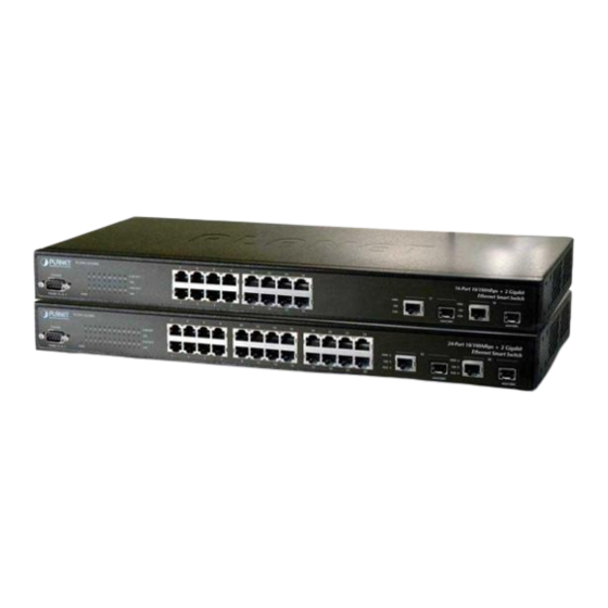
RJ-45 10/100Mbps ports. The Switch also provides up to two 10/100/1000Mbps ports and 2-SFP interfaces for cost effective high-performance network connectivity. With its 8.8Gbps non-blocking switch fabric, the PLANET Switch can also provide a local, high band- width, Fast Ethernet network for your departmental backbone plus the ability to trunk four ports (800Mbps) to enable switch-to-switch backbone. - Page 10 Figure 2-2 shows front panel of FGSW-2620RS. Figure 2-2 PLANET FGSW-2620RS Front Panel 2.1.3 LED Indicators System Color Function Green Lit: Power on Per 10/100Mbps port Function Color Lit: indicate the link through that port is successfully es- tablished. LNK/ACT...
-
Page 11: Installing A Fgsw-1820Rs/Fgsw-2620Rs
2.1.4 10/100/1000Base-T port / SFP interfaces The TP / SFP interfaces #17, #18 or #25, #26 of FGSW-1820RS /FGSW-2620RS can be a 10/100Base-TX, 1000Base-T or 1000Base-SX/LX/LX WDM switching port. Please refer to the section 3.2.4.1 Port for the detailed installation and settings. -
Page 12: Rack Mounting
front of the Switch. B. Connect the other end of the cable to the network devices such as printer serv- ers, workstations or routers…etc. Connection to the Switch requires UTP Category 5 network cabling with RJ-45 tips. For more information, please see the Cabling Note: Specification in Appendix A. - Page 13 Figure 2-5 Mounting the Switch in a Rack Step6: Proceed with the steps 4 and steps 5 of section 2.2.1 Desktop Installation to connect the network cabling and supply power to your Switch.
-
Page 14: Console Configuration
Switch operate more effectively. This section will describe the common usage of the Switch Smart Configuration. The following section will base on the console screens of FGSW- 2620RS, for FGSW-1820RS the display will be the same to FGSW- Note: 2620RS. 3.1 Preparing for configuration 3.1.1 Connecting a PC or Terminal to the RS-232 Port... - Page 15 Figure 3-1 Console Port Settings for smart functions 3.1.3 Power-up Self-test Status As the Switch powers on, it goes through a self-test process to ensure proper operations of the Switch hardware. The messages will be displayed to show the test progress. When the test completes successfully, the system will display a login screen.
-
Page 16: Getting Started
3.1.4 Login After the self-test completes successfully, the screen in figure 3-3 appears. Login is required to access the console interface. The factory default username is “admin” without password. You may change it in the Password. To access to the Main Menu, please always enter the correct username and password. - Page 17 screen and press the ”S” key for save the current configuration. Please refer to figure 3-4 for available options on main menu. Figure 3-4 Main Menu Screen 1. Status Allow user to view the basic information of the Switch. The available options are Switch overview, MIB counter and Port Status.
- Page 18 Figure 3-5 Status Screen Object Description Overview Display the Switch information. Explained in section 3.2.3.1 MIB Counter Display the traffic counter on each port. Explained in sec- tion 3.2.3.2 Port Status Display the current status of each port. Explained in sec- tion 3.2.3.3 Table 3-2 Descriptions of the Status screen Objects 3.2.3.1 Overview...
- Page 19 Figure 3-7 MIB Counter Screen Item Description 1 / 2 KEY Page up / Page down. 0 KEY Return to the previous menu. F KEY Refresh screen. C KEY Clean all counter traffic on each port. P/ X KEY Start / Stop polling. T KEY Toggle Drop/ CRC/ Collision.
- Page 20 Item Description 1 / 2 KEY Page up / Page down. 0 KEY Return to the previous menu. F KEY Refresh screen. Table 3-4 Guideline within the Port Status screen 3.2.4 Port Configuration Press 2 on your keyboard to access the screen of Configuration from the Main Menu screen (please see the figure 3-4).
- Page 21 Device Features Allow user to disable or enable IGMP Snooping and indicate the IP Multicast Router Port. Explained in section 3.2.4.8. Table 3-5 Descriptions of the Configuration screen Objects 3.2.4.1 Port Press 1 on your keyboard to access the screen of Port from the Configuration screen (please see the figure 3-9).
- Page 22 1. Fields with gray color is recommended setting in the Switch. 2. NC means no communication. 3. 1000M Full setting can be found only in port #17/18 of FGSW-1820RS or port #25/26 of FGSW-2620RS. Though device with forced full-duplex mode build the link with the Switch, the performance could be bad due to the devices runs in Full while the Switch runs in Half-duplex.
- Page 23 Trunking screen Objects. The Trunking Configuration menu controls the trunking or the so-called Link Aggregation function. There are 6/8 Trunk groups in the FGSW-1820RS/ FGSW-2620RS can be bundled together to form a high-speed trunk. Please use I / M (Up / Down) key to move the high-light to the object and press the “Space Bar”...
- Page 24 Object Description Half duplex back Provide disable or enable half duplex backpressure flow. pressure flow To disable will turn off the half-duplex back pressure con- trol and drop the packets without sending out any collision from that Switch port after the Switch’s data buffer over- flow.
- Page 25 Priority weight ration Use “M” key to move down to Priority weight ration (high:low) then use Space key to select the ration priority. Avail- able weights, 1:0; 4:1, 8:1, 16:1. Default: 16:1. Force set high-priority Use “M” key to move down the cursor and select the port ports, by Space toggle, that you would like to set base on the QoS options above.
- Page 26 Figure 3-15 VLAN Global Control Screen Object Description VLAN function Allow disable or enable VLAN function. Default: disable Unicast packet Allow disable or enable the packet to be forward to a des- Inter- tination port at different VLAN. VLAN Leaky Default: disable ARP broadcast Allow to disable or enable ARP frame to broadcast to all...
- Page 27 3.2.4.7 VLAN Member Setup Press 7 on your keyboard to access the screen of VLAN Member Setup from the Configuration screen (please see the figure 3-9). The screen of VLAN Member Setup in figure 3-16 appears. Figure 3-16 VLAN Member Setup Screen Port-based VLAN setup procedure: 1.Please press “E”...
- Page 28 Object Description IGMP Snooping Allow disable or enable IGMP Snooping. This function is support the ability of IGMP Control packets and IP multicast data packets to learn the multicast router port and group address member port into multicast address table. Default: disable Table 3-12 Device Features Screen Objects 3.2.5 Security Press 3 on your keyboard to access the screen of Security from the Main Menu screen...
- Page 29 Object Description Trunk Link Warning Display the trunk status at each group when trunk is en- abled. Network loop Fault Display the information loop detect when loop occur on Port Detected each port. Table 3-13 Diagnostics Screen Objects 3.2.7 Password Press 5 on your keyboard to access the screen of Password from the Main Menu screen (please see the figure 3-4).
- Page 30 2. Please press “Enter” to execute current configuration. Figure 3-22 Change username successfully Screen 3 Please press “F” to refresh the screen. 4 Please press “2” key to change the password, the screen in figure 3-23 & 3-24 appears. Figure 3-23 Change password Screen 5.
- Page 31 3.2.8 Reboot Press 6 on your keyboard to access the screen of Reboot from the Main Menu screen (please see the figure 3-4). The screen of Reboot in figure 3-25 appears. Figure 3-25 Reboot Switch Screen Reboot and reset switch to default mode procedure: 1.
- Page 32 Figure 3-28 Reboot Switch Screen Figure 3-29 Reboot Switch Screen Choose “D” Default to reset the Switch to default mode. Not include the modified username and password. Please memorize the new username Notice: and password after change it. 3.2.9 Logout Press 7 on your keyboard to access the screen of Logout from the Main Menu screen (please see the figure 3-4).
-
Page 33: Switch Operation
Press any key then the console login screen appears again. The screen in figure 3-31 appears. Figure 3-31 Switch Login Screen 4. SWITCH OPERATION 4.1 Address Table The Switch is implemented with an address table. This address table composed of many entries. -
Page 34: Auto-Negotiation
The Ethernet Switch scans the destination address from the packet-header, searches the routing table provided for the incoming port and forwards the packet, only if required. The fast forwarding makes the switch attractive for connecting servers directly to the network, thereby increasing throughput and availability. -
Page 35: Appendix A Networking Connection
Some stations cannot talk to other stations located on The other port Solution: Please check the VLAN settings, trunk settings, or port enabled / disabled status. Performance is bad Solution: Check the full duplex status of the Ethernet Switch. If the Ethernet Switch is set to full duplex and the partner is set to half duplex, then the performance will be poor. -
Page 36: Cable Pin Assignments
10/100Mbps, 10/100Base-TX RJ-45 Connector pin assignment Contact MDI-X Media Dependant Interface Media Dependant Interface -Cross Tx + (transmit) Rx + (receive) Tx - (transmit) Rx - (receive) Rx + (receive) Tx + (transmit) Not used Rx - (receive) Tx - (transmit) Not used A.2 RJ-45 cable Pin Assignments The standard RJ-45 receptacle/connector... - Page 38 Part No.:2010-A81120-000...