Table of Contents
Advertisement
EMPIRE
EMPIRE
Comfort Systems
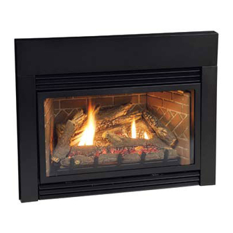
DIRECT vENT
GAS FIREpLACE HEATER
MODELS
Dv25IN33L(N,p)-3
Dv25IN73L(N,p)-1
Dv(33,35)IN33(N,p)-4
Dv(33,35)IN73(N,p)-2
GAS-FIRED
UL FILE NO. MH30033
This appliance may be installed in an aftermarket,
permanently located, manufactured home (USA only)
or mobile home, where not prohibited by state or local
codes.
This appliance is only for use with the type of gas
indicated on the rating plate. This appliance is not
convertible for use with other gases, unless a certified
kit is used.
WARNING: If not installed, operated and maintained
in accordance with the manufacturer's instructions,
this product could expose you to substances in fuel
or from fuel combustion which can cause death or
serious illness.
INSTALLATION INSTRUCTIONS
OWNER'S MANUAL
AND
FIREPLACE INSERT
Installer:
Leave this manual with the appliance.
Consumer: Retain this manual for future reference.
WARNING: If the information in these instructions
are not followed exactly, a fire or explosion may
result causing property damage, personal injury
or loss of life.
— Do not store or use gasoline or other flammable
vapors and liquids in the vicinity of this or any
other appliance.
— WHAT TO DO IF YOU SMELL GAS
•
Do not try to light any appliance.
•
Do not touch any electrical switch; do not use
any phone in your building.
•
Immediately call your gas supplier from a
neighbor's phone. Follow the gas supplier's
instructions.
•
If you cannot reach your gas supplier, call the
fire department.
— Installation and service must be performed by a
qualified installer, service agency or the gas sup-
plier.
Page 1
Advertisement
Table of Contents
Troubleshooting

Related Manuals for Empire Comfort Systems DV25IN33L-3


Summary of Contents for Empire Comfort Systems DV25IN33L-3
-
Page 1: Direct Vent
INSTALLATION INSTRUCTIONS EMPIRE EMPIRE OWNER’S MANUAL Comfort Systems FIREPLACE INSERT DIRECT vENT GAS FIREpLACE HEATER MODELS Dv25IN33L(N,p)-3 Dv25IN73L(N,p)-1 Dv(33,35)IN33(N,p)-4 Dv(33,35)IN73(N,p)-2 GAS-FIRED Installer: Leave this manual with the appliance. Consumer: Retain this manual for future reference. UL FILE NO. MH30033 This appliance may be installed in an aftermarket, WARNING: If the information in these instructions permanently located, manufactured home (USA only) are not followed exactly, a fire or explosion may... -
Page 2: Table Of Contents
TABLE OF CONTENTS SECTION pAGE Important Safety Information ....................3 Safety Information for Users of LP Gas ................4 Introduction ........................5 Specifications ........................6 Fireplace Insert Dimensions ....................7 Mantle and Trim Clearances ....................8 Gas Supply ........................9 Venting and Installation ....................10-12 Vertical Termination ...................... -
Page 3: Important Safety Information
IMpORTANT SAFETY INFORMATION Before enclosing the vent pipe assembly, operate the appliance to ensure it is venting properly. DO NOT OPERATE THIS APPLIANCE WITHOUT GLASS FRONT PANEL INSTALLED • Adequate accessibility clearances for servicing and DANGER: Indicates a hazardous situation which, if not proper operation should be maintained. -
Page 4: Safety Information For Users Of Lp Gas
SAFETY INFORMATION FOR USERS OF Lp-GAS Propane (LP-Gas) is a flammable gas which can cause fires SOME pOINTS TO REMEMBER and explosions. In its natural state, propane is odorless and • Learn to recognize the odor of LP-gas. Your local LP-Gas colorless. -
Page 5: Introduction
INTRODUCTION Instructions to Installer Any alteration of the original design, installed other than as 1. Installer must leave instruction manual with owner after shown in these instructions or use with a type of gas not installation. shown on the rating plate is the responsibility of the person 2. Installer must have owner fill out and mail warranty card supplied and company making the change. -
Page 6: Specifications
SpECIFICATIONS Dv25IN(3,7)3L MODELS Surround Description Input Btu/hr Maximum 25,000 25,000 Contemporary Black Surround for DV25IN, 6 x Input Btu/hr Minimum 17,000 17,000 S253BL 3 inch KWH (Maximum) Contemporary Black Surround for DV33IN, 6 x S333BL KWH (Minimum) 3 inch Orifice #53 (0.0596) #42 (0.0935) Contemporary Black Surround for DV35IN, 6 x S353BL Air Shutter Opening Full Open 1/8” 3 inch Dv33IN(3,7)3L MODELS Contemporary Black Surround for DV25IN, 6 x S256BL 6 inch... -
Page 7: Fireplace Insert Dimensions
FIREpLACE INSERT DIMENSIONS • Whether optional accessories - devices such as a wall switch When planning a fireplace insert installation, it’s necessary to or remote control - are desired. determine: • Electrical supply requirements for blower. • The vent system configuration to be used. • Proper opening size of fireplace required for installation of • Gas supply piping. the fireplace insert. Dv FIREpLACE INSERT DIMENSIONS MODEL DV25IN 19-3/4” 14-1/2” 11-1/8” 25-1/4” 12-3/4” 17” 18-5/16” 27” 6-3/4” 9” 20” 25-5/8” 40”... -
Page 8: Mantle And Trim Clearances
MANTLE AND TRIM CLEARANCES Figure 3 Distance from Height Above Top of Insert Face of Fireplace 10” 23” 9-1/4” 22” 8-3/4” 21” 8” 20” 7-1/4” 19” 6-1/2” 18” 6” 17” 5-1/4” 16” 4-1/2” 15” 3-3/4” 14” 3” 13” 2-1/2” 12” 1-3/4”... -
Page 9: Gas Supply
GAS SUppLY The gas pipeline can be brought in through the right or left side of Installing the Main Gas Cock the appliance. The insert has a Flexline with shutoff valve located on Each appliance should have its own manual gas cock. the right side when facing the unit. See Figures 5 and 6. Consult A manual main gas cock should be located in the vicinity of the unit. -
Page 10: Venting And Installation
vENTING AND INSTALLATION 1. Before beginning, remove glass door and log package from 7. To assure top performance, safety and efficiency, inserts unit. Also check to make sure there is no hidden damage to must be installed with an approved flue liner as per CAN/CGA the unit. Take a minute and plan out the gas, venting and elec- B-149 or National Fuel Code ANSI Z223 and these instruc- trical route. It is best to start with the gas line first, followed by tions. the chimney liner and electrical supply requirements. NOTICE: The following statement is also provided on a sepa- 2. Minimum fireplace opening requirements are shown in rate label plate in the instruction packet. - Page 11 vENTING AND INSTALLATION vent System Approvals Connecting the vent pipe Figure 8 shows the vent termination caps and systems approved CAUTION for use with these models. Approved vent system terminations are labeled for identification. 3-inch diameter listed flexible aluminum Sharp edges. Always use gloves when installing. or stainless steel gas vent is used for both the incoming combustion air and exhaust vent pipes.
- Page 12 vENTING AND INSTALLATION Figure 8 Page 12 32227-0-0513...
-
Page 13: Vertical Termination
vERTICAL TERMINATION Determining Minimum vent Height Above the Roof. vertical Through the Roof Applications The Gas Fireplace Insert has been approved for: WARNING a) Vertical installations up to 35 feet in height (top of insert to cap). b) Two sets of 45 degree elbow offsets (bends in flexvent) within Major U.S. building codes specify minimum chimney and/or the vertical installation. From 0 to a maximum of 8 ft. of vent vent height above the roof top. -
Page 14: Alternate On/Off Switch Installation
ALTERNATE ON/OFF SWITCH INSTALLATION WIRING THE FIREpLACE Traditional Cast Iron Surrounds NOTICE: Electrical wiring must be installed by a licensed Find the coiled low voltage wire assembly and ON/OFF switch electrician. located in the instruction packet. 2. Attach the flag terminal ends to the “TH/TP” and “TH” termi- nals on the front terminal block of the gas valve. See Figure CAUTION DISCONNECT REMOTE CONTROLS IF YOU ARE ABSENT FOR EXTENDED TIME PERIODS. -
Page 15: Surround Panel Installation
SURROUND pANEL INSTALLATION INSTALLING THE TRIM SURROUNDS Combustible materials MUST NEVER overlap onto the front face. WARNING WHEN FINISHING THE FIREpLACE INSERT, NEvER OB- STRUCT OR MODIFY THE AIR INLET/OUTLET LOUvERS ON THE FIREpLACE INSERT IN ANY MANNER. Figure 15 Figure 14 32227-0-0513 Page 15... -
Page 16: Blower Accessory Information
BLOWER ACCESSORY INFORMATION The appliance, when installed must be electrically connect- ed and grounded in accordance with local codes or, in the absence of local codes, with the current CSA C22.1 Cana- dian Electrical Code. U.S. Installations, follow local codes and the National Elec- trical Code, ANSI/NFpA No. -
Page 17: Log Placement
LOG pLACEMENT Before you begin: This fireplace insert is supplied with a set of CAUTION seven ceramic fiber logs. Do not handle these logs with your bare hands. Always wear gloves to prevent skin irritation from ceramic Decorative Rock is not included with the Fireplace Insert, fibers. After handling logs, wash your hands gently with soap and however it may be purchased separately and placed only on the water to remove any traces of fiber. firebox floor. Do Not place decorative rock or rock wool on the The positioning of logs is critical to safe and clean operation of this logs or burner assembly. -
Page 18: Operating Instructions
OpERATING INSTRUCTIONS 750 Millivolt System The OWNER should carefully read and follow these operating The standing pilot (750 millivolt system) is a continuous burning instructions at all times. Lower the door assembly to view the gas pilot. The pilot remains ON even when the main burner is OFF. controls for the fireplace. -
Page 19: Standing Pilot Lighting Instructions
STANDING pILOT LIGHTING INSTRUCTIONS FOR YOUR SAFETY READ BEFORE LIGHTING WARNING: If you do not follow these instructions exactly, a fire or explosion may result causing property damage, personal injury or loss of life. A. This appliance has a pilot which must be lighted by hand. When • If you cannot reach your gas supplier, call the fire depart- lighting the pilot, follow these instructions exactly. ment. -
Page 20: Standing Pilot Wiring
STANDING pILOT WIRING For Standing pilot Ignition Wiring WARNING Appliance Requirements DO NOT CONNECT THE 110-120 vAC TO THE WALL SWITCH OR THE CONTROL vALvE WILL BE DESTROYED. WARNING DO NOT CONNECT 110-120 vAC TO THE GAS CONTROL vALvE OR THE AppLIANCE WILL MALFUNCTION AND THE WARNING vALvE WILL BE DESTROYED. -
Page 21: Standing Pilot Troubleshooting
Flame impingement on logs incorrect. —Check REMOTE/OFF/ON switch and wires for proper —Check and adjust log position. See Page 17. Contact connections. Place jumper wires across terminal at switch. Empire Comfort Systems, Inc. If burner comes on, replace defective switch. If OK, place Debris around throat of main burner. jumper wires across switch wires at gas valve-if burner —Inspect the opening at the base of the main burner. -
Page 22: Ipi Electronic System Operating Instructions
IpI ELECTRONIC SYSTEM OpERATING INSTRUCTIONS 5.25 vDC ELECTRONIC CONTROL vALvE The gas valve has inlet and outlet pressure taps as shown in Figure 23. Refer to page 9 for gas pressure requirements. The electronic control valve system includes the ability to switch the pilot from a standing pilot mode to an intermittent pilot mode. Note: The gas control has a manual HI/LO flame adjustment •... -
Page 23: Ipi Electronic System Wiring Diagram
IpI ELECTRONIC SYSTEM WIRING DIAGRAM If any of the original wire as supplied with this unit must be replaced, it must be replaced with equivalent gauge and tem- perature rated wire. This appliance is only for use with the type of gas indicated on the rating plate and may be installed in an aftermarket, permanently located, manufactured (mobile) home where not prohibited by local codes. This appliance is not convertible for use with other gases, unless a certified kit is used. -
Page 24: Intermittent Pilot Lighting Instructions
INTERMITTENT pILOT LIGHTING INSTRUCTIONS FOR YOUR SAFETY READ BEFORE LIGHTING WARNING: If you do not follow these instructions exactly, a fire or explosion may result causing property damage, personal injury or loss of life. A. This appliance has a pilot which must be lighted by hand. When C. Use only your hand to push in or turn the gas control knob. lighting the pilot, follow these instructions exactly. Never use tools. If the knob will not push in or turn by hand, don't try to repair it; call a qualified service technician. Force B. -
Page 25: Intermittent Control System Troubleshooting
INTERMITTENT CONTROL SYSTEM TROUBLESHOOTING Brief Description of the Components The gas valve is fitted with a manual HI/LO knob to allow for man- ual modulation of the gas outlet pressure to the appliance burner. The controls are designed to be used with either LPG or Natural Gas and can be converted by use of an OEM supplied conversion kit. -
Page 26: Intermittent Control System Troubleshooting
INTERMITTENT CONTROL SYSTEM TROUBLESHOOTING Page 26 32227-0-0513... -
Page 27: Intermittent Control System Troubleshooting
INTERMITTENT CONTROL SYSTEM TROUBLESHOOTING 32227-0-0513 Page 27... -
Page 28: Insert Maintenance And Service
INSERT MAINTENANCE AND SERvICE Cleaning Logs Although the frequency of servicing and maintenance will depend Use a soft brush attachment on a vacuum cleaner to gently remove on use and the type of installation, you should have a qualified dust or soot deposits from logs and burner. service technician perform an appliance checkup at the beginning of each heating season. Specific guidelines regarding each Cleaning Glass Door appliance maintenance task are listed below. -
Page 29: Decorative Accessories
DECORATIvE ACCESSORIES The following accessory parts can be obtained from your Empire Comfort Systems dealer. If you need additional information beyond what your dealer can furnish, contact Empire Comfort Systems Inc., Nine Eighteen Freeburg Ave., Belleville, Illinois 62220. • Black •... -
Page 30: Decorative Accessories
DECORATIvE ACCESSORIES Decorative Fronts Style Model Number Style Model Number Tribecca DVD(25,33,35)C(BL,HP,SS) Manhattan DVF(25,33,35)N(BL,HP) • Black • Black • Hammered Pewter • Hammered Pewter • Stainless Steal Note: Must also use 3-sided Note: Must also use 3-sided surround. surround. Transom DVD(25,33,35)D(BL,HP,SS) Eclipse DVF(25,33,35)R(BL,HP,SS) -
Page 31: Parts View
INSERT pARTS vIEW 32227-0-0513 Page 31... -
Page 32: Parts List
INSERT pARTS LIST pART NUMBER INDEX DESCRIpTION Dv25IN33 Dv25IN73 Dv33IN33L Dv33IN73L Dv35IN33L Dv35IN73L 22950 22950 22950 22950 22950 22950 GUIDE, FLUE CONNECTOR 23309 23309 23211 23211 23211 23211 VENT SLIDE PLATE ASSEMBLY R9188 R9188 R9188 R9188 R9188 R9188 GASKET, TOP R9192 R9192 R9196... - Page 33 INSERT pARTS LIST pART NUMBER INDEX DESCRIpTION Dv25IN33 Dv25IN73 Dv33IN33L Dv33IN73L Dv35IN33L Dv35IN73L 16223 16223 16223 16223 16223 16223 SPRING RETAINER ASSEMBLY 25548 25548 25548 25548 FLAME SHIELD, LEFT M163 M163 M163 M163 M163 M163 GASKET, FLUE CONNECTOR 23009 23009 23009 23009 23009...
-
Page 34: Master Parts Distributor List
MASTER pARTS DISTRIBUTOR LIST To Order Parts Under Warranty, please contact your local Empire dealer. See the dealer locator at www.empirecomfort. com. To provide warranty service, your dealer will need your name and address, purchase date and serial number, and the nature of the problem with the unit. -
Page 35: Warranty
WARRANTY Empire Comfort Systems Inc. warranties this hearth product to be free from defects at the time of purchase and for the periods speci- fied below. Hearth products must be installed by a qualified technician and must be maintained and operated safely, in accordance with the instructions in the owner’s manual. This warranty applies to the original purchaser only and is not transferable. All warranty repairs must be accomplished by a qualified gas appliance technician. Limited Lifetime Parts Warranty – Combustion Chamber, Heat Exchanger, and Factory-Installed Glass If the combustion chamber, heat exchanger (see parts list) or factory-installed glass fails because of defective workmanship or material, Empire will repair or replace at Empire’s option. - Page 36 Empire Comfort Systems Inc. EMPIRE EMPIRE 918 Freeburg Ave. Belleville, IL 62220 If you have a general question about our products, please e-mail us at info@empirecomfort.com. If you have a service or repair question, please contact your dealer. Comfort Systems www.empirecomfort.com Page 36 32227-0-0513...