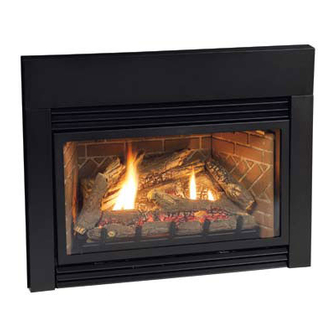
Empire Comfort Systems DV25IN33LN-3 Installation Instructions And Owner's Manual
Direct vent gas fireplace heater
Hide thumbs
Also See for DV25IN33LN-3:
- Installation instructions and owner's manual (36 pages) ,
- Installation instructions and owner's manual (28 pages) ,
- Installation instructions and owner's manual (36 pages)
Table of Contents
Advertisement
WARNING: If not installed, operated and maintained
in accordance with the manufacturer's instructions,
this product could expose you to substances in fuel
or from fuel combustion which can cause death or
serious illness.
FIRE OR EXPLOSION HAZARD
Failure to follow safety warnings exactly
could result in serious injury, death or
property damage.
— Do not store or use gasoline or other flam-
mable vapors and liquids in the vicinity of
this or any other appliance.
— WHAT TO DO IF YOU SMELL GAS
•
Do not try to light any appliance.
•
Do not touch any electrical switch; do
not use any phone in your building.
•
Leave the building immediately.
•
Immediately call your gas supplier
from a neighbor's phone. Follow the
gas supplier's instructions.
•
If you cannot reach your gas supplier,
call the fire department.
— Installation and service must be per-
formed by a qualified installer, service
agency or the gas supplier.
WARNING
A barrier designed to reduce the risk of burns from the
hot viewing glass is provided with this appliance and shall
be installed for the protection of children and other at-risk
individuals.
Note: Barrier required, may be sold separately.
INSTALLATION INSTRUCTIONS
AND OWNER'S MANUAL
INSTALLER: Leave this manual with the appliance.
CONSUMER: Retain this manual for future reference.
WARNING
HOT GLASS
CAUSE BURNS.
DO NOT TOUCH
UNTIL COOLED.
NEVER
ALLOW CHILDREN
TO TOUCH GLASS.
GAS FIREPLACE HEATER
FIREPLACE INSERT MODELS
UL FILE NO. MH30033
This appliance may be installed in
an aftermarket, permanently located,
manufactured home (USA only) or mobile
home, where not prohibited by state or local
codes.
This appliance is only for use with the type
of gas indicated on the rating plate. This
appliance is not convertible for use with other
gases, unless a certified kit is used.
WILL
GLASS
DIRECT VENT
DV25IN33L(N,P)-3
DV25IN73L(N,P)-1
DV(33,35)IN33L(N,P)-4
DV(33,35)IN73L(N,P)-2
GAS-FIRED
Page 1
Advertisement
Table of Contents
Troubleshooting

Related Manuals for Empire Comfort Systems DV25IN33LN-3


Summary of Contents for Empire Comfort Systems DV25IN33LN-3
-
Page 1: Installation Instructions
INSTALLATION INSTRUCTIONS AND OWNER’S MANUAL INSTALLER: Leave this manual with the appliance. CONSUMER: Retain this manual for future reference. DIRECT VENT WARNING: If not installed, operated and maintained in accordance with the manufacturer’s instructions, GAS FIREPLACE HEATER this product could expose you to substances in fuel or from fuel combustion which can cause death or FIREPLACE INSERT MODELS serious illness. -
Page 2: Table Of Contents
TABLE OF CONTENTS SECTION PAGE Specifications ........................3 Accessories ........................4 Important Safety Information ...................5-6 Safety Information for Users of LP-Gas ................7 Introduction ........................8 Fireplace Insert Dimensions ....................9 Mantel and Trim Clearances .................... 10 Gas Supply ......................... 11-12 Venting and Installation ....................13-15 Vertical Termination .....................16-17 Alternate On/Off Switch Installation ................. -
Page 3: Specifications
SPECIFICATIONS DV25IN(3,7)3L DV33IN(3,7)3L DV35IN(3,7)3L Input BTU/Hr Maximum 25,000 25,000 33,000 33,000 35,000 35,000 Input BTU/Hr Minimum 17,000 17,000 25,000 23,000 27,000 25,000 KWH (Maximum) 9.57 9.57 10.15 10.15 KWH (Minimum) 7.30 6.67 7.83 7.30 Orifice #53 (0.0596) #42 (0.0935) 1.55mm #36 (0.1065) 1.65mm (0.65) #35 (.110) -
Page 4: Accessories
ACCESSORIES Venting Kits Description Contents One piece of 35’ FlexVent (split for 17 1/2’ vent run), Round Cap, Flashing, connectors, DVKI Vertical Vent Kit 17 1/2’ and clamps. Recommended when installing to an existing round fireplace chimney pipe. Two pieces of 25’ FlexVent, Rectangle Cap, Flashing, connectors, and clamps Recom- DVVK3FV Vertical Vent Kit 25’... -
Page 5: Important Safety Information
IMPORTANT SAFETY INFORMATION Definitions DANGER: Indicates a hazardous situation which, if not avoided, will result in death or serious injury. WARNING: Indicates a hazardous situation which, if not avoided, could result in death or serious injury. CAUTION: Indicates a hazardous situation which, if not avoided, could result in minor or moderate injury. NOTICE: Addresses practices not related to personal injury. -
Page 6: Important Safety Information
IMPORTANT SAFETY INFORMATION Maintenance Precautions • A yearly examination and cleaning of the venting system • Installation and repair should be done by a qualified of the solid-fuel burning fireplace must be performed by service person. The appliance should be inspected a qualified agency. -
Page 7: Safety Information For Users Of Lp-Gas
SAFETY INFORMATION FOR USERS OF LP-GAS Propane (LP-Gas) is a flammable gas which can cause fires SOME POINTS TO REMEMBER and explosions. In its natural state, propane is odorless and • Learn to recognize the odor of LP-gas. Your local LP-Gas colorless. -
Page 8: Introduction
Modification of the fireplace insert or direct vent system. performed only by a qualified agency. The term “qualified agency” • Installation other than as instructed by Empire Comfort Systems, means any individual, firm, corporation or company which either in Inc. -
Page 9: Fireplace Insert Dimensions
FIREPLACE INSERT DIMENSIONS • Whether optional accessories - devices such as a wall switch When planning a fireplace insert installation, it’s necessary to or remote control - are desired. determine: • Electrical supply requirements for blower. • The vent system configuration to be used. •... -
Page 10: Mantel And Trim Clearances
MANTEL AND TRIM CLEARANCES FINISHED WALL COMBUSTIBLE 12” MANTEL/TRIM AREA TOP OF INSERT Figure 2 SURROUND PANELS Distance from Height Above Top of Insert Face of Fireplace 10” 23” 9-1/4” 22” 8-3/4” 21” 8” 20” 7-1/4” 19” 6-1/2” 18” 6” 17”... -
Page 11: Gas Supply
GAS SUPPLY If the factory factory built fireplace has no gas access hole(s) provided, Gas Supply Pressure (inches w.c.) an access hole of 1.5 in (37.5 mm) or less may be drilled through the lower sides or bottom of the firebox in a proper workmanship-like Minimum Normal Maximum... - Page 12 GAS SUPPLY NOTICE: The millivolt gas controls are equipped with a captured screw type pressure test point, therefore it is not necessary to provide a 1/8” test point up stream of the control. When using copper or flex connector use only approved fittings. The appliance and it’s individual shut off valve must be disconnected from supply piping system during any pressure testing of that system at test pressures in excess of 1/2 psig (3.5kPa).
-
Page 13: Venting And Installation
VENTING AND INSTALLATION Before beginning, remove glass door and log package from To assure top performance, safety and efficiency, inserts unit. Also check to make sure there is no hidden damage to must be installed with an approved flue liner as per CAN/CGA the unit. - Page 14 VENTING AND INSTALLATION Vent System Approvals Connecting the Vent Pipe Figure 8 shows the vent termination caps and systems approved CAUTION for use with these models. Approved vent system terminations are labeled for identification. 3-inch diameter listed flexible aluminum Sharp edges. Always use gloves when installing. or stainless steel gas vent is used for both the incoming combustion air and exhaust vent pipes.
-
Page 15: Venting And Installation
VENTING AND INSTALLATION RECTANGULAR TERMINATION CAP NOTE: LONG EXTENSION (DVVK3FV KIT) TUBE FOR INLET VENT CONNECTION ROUND TERMINATION CAP (DVKI KIT) VENT CLAMPS ROUND CO-LINEAR TO CO-AXIAL ADAPTOR USE HIGH TEMP RETAINER SCREWS MAY SEALANT ON VENT BE INSTALLED THROUGH CONNECTIONS THE VENT CLAMPS TO ENSURE POSITIVE... -
Page 16: Vertical Termination
VERTICAL TERMINATION Determining Minimum Vent Height Above the Roof. Vertical Through the Roof Applications The Gas Fireplace Insert has been approved for: WARNING a) Vertical installations up to 35 feet in height (top of insert to cap). b) Two sets of 45 degree elbow offsets (bends in flexvent) within Major U.S. -
Page 17: Vertical Termination
VERTICAL TERMINATION Optional Inlet Air Restrictor Plate Installation Note: For certain installations wtih 20 to 35 feet vertical vent- ing, or in high wind areas, the installation of the inlet air restrictor plate may be required. The optional restrictor plate is included in the instruction packet. If applicable, remove the glass door, log set and brick liner panels and set aside. -
Page 18: Alternate On/Off Switch Installation
ALTERNATE ON/OFF SWITCH INSTALLATION WIRING THE FIREPLACE Traditional Cast Iron Surrounds NOTICE: Electrical wiring must be installed by a licensed Find the coiled low voltage wire assembly and ON/OFF switch electrician. located in the instruction packet. Attach the flag terminal ends to the “TH/TP” and “TH” termi- nals on the front terminal block of the gas valve. -
Page 19: Blower Accessory Information
BLOWER ACCESSORY INFORMATION The appliance, when installed must be electrically connect- ed and grounded in accordance with local codes or, in the absence of local codes, with the current CSA C22.1 Cana- dian Electrical Code. U.S. Installations, follow local codes and the National Elec- trical Code, ANSI/NFPA No. -
Page 20: Log Identification
LOG IDENTIFICATION Part Number Front View Top View Description DV25IN DV(33,35)IN Log A R9256 R9218 Log B R9257 R9219 Log C R9255 R9217 Log D R9259 R9251 Log E R9258 R9220 Log F R9260 R9252 Log G R9261 R9253 Page 20 35657-4-1015... -
Page 21: Log Placement
LOG PLACEMENT Before you begin: This fireplace insert is supplied with a set of seven ceramic fiber logs. Do not handle these logs with your bare hands. Always wear gloves to prevent skin irritation from ceramic fibers. After handling logs, wash your hands gently with soap and water to remove any traces of fiber. - Page 22 LOG PLACEMENT 1. Place Log A on the front log support ledge between the left tab and the grate tangs. Log A will touch the back of the grate tangs. See image below. Page 22 35657-4-1015...
- Page 23 LOG PLACEMENT 2. Place Log B on the front log support ledge between the left tab and the grate tangs. Log B will touch the back of the grate tangs. See image below. 35657-4-1015 Page 23...
- Page 24 LOG PLACEMENT 3. Next install Log C. It will be centered left to right and placed all the way to the back of the firebox, on top of the rear log support. NOTICE: DV25IN models incorporate two small tabs in the rear log support that keep the back log positioned correctly.
- Page 25 LOG PLACEMENT 4. Locate Log D. It will have two locator pin holes on the bottom flat surface. Align the two holes with the two left pins on the burner assembly. Make sure this log is not raised up off of the burner. The flat bottom surface must be completely resting flat on the top of the burner surface.
- Page 26 LOG PLACEMENT 5. Install Log E. It will also have two locator pin holes on the bottom flat surface. Align these two holes with the two right pins on the burner assembly. Make sure this log is not raised up off of the burner. The flat bottom surface must be completely resting flat on the top of the burner surface.
- Page 27 LOG PLACEMENT 6. Add Log F by placing the locator pin hole on the bottom of the twig with the pin on top of the center right log. The tip of Log F will rest on top of Log C near the right end. See image below. 35657-4-1015 Page 27...
- Page 28 LOG PLACEMENT 7. Add Log G by placing the locator pin hole on the bottom of the log with the pin on top of Log D. The long branch of Log G will rest in a small groove on top of Log C. Note: The flat side of the log will face the left side liner. This groove is near the left end of Log C.
-
Page 29: Log Placement
LOG PLACEMENT 8. The log assembly is complete. 9. Replace the glass door assembly onto the fireplace insert. 10. Secure the glass door with the two spring clamps located under the firebox. 11. Re-install the upper and lower louver assemblies by aligning the end tabs with the slots provided in the outer face flanges of the insert. -
Page 30: Operating Instructions
OPERATING INSTRUCTIONS 750 Millivolt System The OWNER should carefully read and follow these operating The standing pilot (750 millivolt system) is a continuous burning instructions at all times. Lower the door assembly to view the gas pilot. The pilot remains ON even when the main burner is OFF. controls for the fireplace. -
Page 31: Standing Pilot Lighting Instructions
STANDING PILOT LIGHTING INSTRUCTIONS FOR YOUR SAFETY READ BEFORE LIGHTING WARNING: If you do not follow these instructions exactly, a fire or explosion may result causing property damage, personal injury or loss of life. A. This appliance has a pilot which must be lighted by hand. When •... -
Page 32: Standing Pilot Wiring
STANDING PILOT WIRING For Standing Pilot Ignition Wiring: Appliance Requirements WARNING WARNING LABEL ALL WIRES PRIOR TO DISCONNECTION WHEN DO NOT CONNECT 110-120 VAC TO THE GAS CONTROL SERVICING CONTROL. WIRING ERRORS CAN CAUSE IM- VALVE OR THE APPLIANCE WILL MALFUNCTION AND THE PROPER AND DANGEROUS OPERATION. -
Page 33: Standing Pilot Troubleshooting
—Check REMOTE/OFF/ON switch and wires for proper —Check and adjust log position. See Page 17. Contact connections. Place jumper wires across terminal at switch. Empire Comfort Systems, Inc. If burner comes on, replace defective switch. If OK, place Debris around throat of main burner. -
Page 34: Ipi Electronic System Operating Instructions
IPI ELECTRONIC SYSTEM OPERATING INSTRUCTIONS 5.25 VDC ELECTRONIC CONTROL VALVE During the operating season (or in power outage periods), it is The electronic control valve system includes the ability to switch the pilot from a standing pilot mode to an intermittent pilot mode. recommended that the pilot remain in the CPI (standing pilot •... -
Page 35: Ipi Electronic System Wiring Diagram
IPI ELECTRONIC SYSTEM WIRING DIAGRAM If any of the original wire as supplied with this unit must be replaced, it must be replaced with equivalent gauge and tem- perature rated wire. This appliance is only for use with the type of gas indicated on the rating plate and may be installed in an aftermarket, permanently located, manufactured (mobile) home where not prohibited by local codes. -
Page 36: Intermittent Pilot Lighting Instructions
INTERMITTENT PILOT LIGHTING INSTRUCTIONS FOR YOUR SAFETY READ BEFORE LIGHTING WARNING: If you do not follow these instructions exactly, a fire or explosion may result causing property damage, personal injury or loss of life. A. This appliance has a pilot which must be lighted by hand. When C. -
Page 37: Intermittent Control System Troubleshooting
INTERMITTENT CONTROL SYSTEM TROUBLESHOOTING Brief Description of the Components The gas valve is fitted with a manual HI/LO knob to allow for man- ual modulation of the gas outlet pressure to the appliance burner. The controls are designed to be used with either LPG or Natural Gas and can be converted by use of an OEM supplied conversion kit. - Page 38 INTERMITTENT CONTROL SYSTEM TROUBLESHOOTING Page 38 35657-4-1015...
- Page 39 INTERMITTENT CONTROL SYSTEM TROUBLESHOOTING 35657-4-1015 Page 39...
-
Page 40: Insert Maintenance And Service
Frequency: Once annually. damaged glass and gasket using materials specified by By: Qualified service technician. Empire Comfort Systems. Task: Brush or vacuum the control compartment, fireplace logs Do not abuse or strike the glass. and burner areas surrounding the logs. -
Page 41: Insert Parts View
INSERT PARTS VIEW WARNING Failure to position parts in accordance with these diagrams or failure to use only parts specifically approved with this appliance may result in property damage or personal injury. 35657-4-1015 Page 41... -
Page 42: Insert Parts List
INSERT PARTS LIST PART NUMBER INDEX DESCRIPTION DV25IN33 DV25IN73 DV33IN33L DV33IN73L DV35IN33L DV35IN73L 22950 22950 22950 22950 22950 22950 GUIDE, FLUE CONNECTOR 23309 23309 23211 23211 23211 23211 VENT SLIDE PLATE ASSEMBLY R9188 R9188 R9188 R9188 R9188 R9188 GASKET, TOP R9192 R9192 R9196... - Page 43 INSERT PARTS LIST PART NUMBER INDEX DESCRIPTION DV25IN33 DV25IN73 DV33IN33L DV33IN73L DV35IN33L DV35IN73L 16223 16223 16223 16223 16223 16223 SPRING RETAINER ASSEMBLY 25548 25548 25548 25548 FLAME SHIELD, LEFT M163 M163 M163 M163 M163 M163 GASKET, FLUE CONNECTOR 23009 23009 23009 23009 23009...
-
Page 44: Master Parts Distributor List
This list changes from time to time. For the current list, please click on the Master Parts button at www.empirecomfort.com. Please note: Master Parts Distributors are independent businesses that stock the most commonly ordered Original Equipment repair parts for Heaters, Grills, and Fireplaces manufactured by Empire Comfort Systems Inc. Dey Distributing Victor Division of F. -
Page 45: Warranty
WARRANTY Empire Comfort Systems Inc. warranties this hearth product to be free from defects at the time of purchase and for the periods speci- fied below. Hearth products must be installed by a qualified technician and must be maintained and operated safely, in accordance with the instructions in the owner’s manual. -
Page 46: Appliance Service History
APPLIANCE SERVICE HISTORY Date Dealer Name Service Technician Name Service Performed/Notes Page 46 35657-4-1015... - Page 47 APPLIANCE SERVICE HISTORY Date Dealer Name Service Technician Name Service Performed/Notes 35657-4-1015 Page 47...
- Page 48 Empire Comfort Systems Inc. 918 Freeburg Ave. Belleville, IL 62220 If you have a general question about our products, please e-mail us at info@empirecomfort.com. If you have a service or repair question, please contact your dealer. Page 48 35657-4-1015...