
Related Manuals for Omega CN63100 Series


Summary of Contents for Omega CN63100 Series
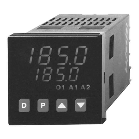
- Page 1 User’ s Guide CN63100/CN63300 Series Shop online at 1/16 DIN Temperature/Process omega.com Controllers e-mail: info@omega.com UL Recognized Component, File # E123489 LP0679A...
- Page 2 European New Approach Directives. OMEGA will add the CE mark to every appropriate device upon certification. The information contained in this document is believed to be correct, but OMEGA accepts no liability for any errors it contains, and reserves the right to alter specifications without notice.
-
Page 3: Table Of Contents
CN63100 Models Without RS-485 and Analog Output · · · · · · · · · · · · · · · · · · · · · · · · · · · · · · · · ·... - Page 4 Configure Module 1 - Input Parameters (1-IN) CN63100 · · · · · · · · · · · · · · · · · · · · · · · · · · · · · · · · ·...
- Page 5 Sensor Fail Power Level (OPFL) CN63100 only· · · · · · · · · · · · · · · · · · · · · · · · · · · · · · · · · · ·...
- Page 6 Alarm Value (AL-1, AL-2) · · · · · · · · · · · · · · · · · · · · · · · · · · · · · · · · · · · · · · · · · · · · · · · · · · · · · · · 41 Alarm Hysteresis (AHYS) ·...
- Page 7 CN63100 OEM Paint Sprayer Application · · · · · · · · · · · · · · · · · · · · · · · · · · · · · · · · · · · ·...
- Page 8 Remote Setpoint Input Check (CN63100 and CN63300) · · · · · · · · · · · · · · · · · · · · · · · · · · · · · · · · ·...
-
Page 9: General Description
GENERAL DESCRIPTION The CN63100 Controller accepts signals from a variety of temperature The optional RS485 serial communication interface provides two-way sensors (thermocouple or RTD elements), while the CN63300 Controller communication between a controller and other compatible equipment such as accepts either a 0 to 10 VDC or 0/4 to 20 mA DC input signal. Both controllers a printer, PLC, HMI, or a host computer. -
Page 10: Installation Description
INSTALLATION DESCRIPTION The controller meets NEMA 4X/IP65 requirements for indoor use to provide a watertight seal in steel panels with a minimum thickness of 0.09 inch, or aluminum panels with a minimum thickness of 0.12 inch. The units are intended to be mounted into an enclosed panel. -
Page 11: Multiple Unit Stacking
MULTIPLE UNIT STACKING The controller is designed for close spacing of multiple units. Units can be stacked either horizontally or vertically. For vertical stacking, install the panel latch with the screws to the sides of the unit. For horizontal stacking, the panel latch screws should be at the top and bottom of the unit. -
Page 12: Connection Description
CONNECTION DESCRIPTION EMC INSTALLATION GUIDELINES 5. In extremely high EMI environments, the use of external EMI suppression Although Red Lion Controls Products are designed with a high degree of devices such as Ferrite Suppression Cores for signal and control cables is immunity to Electromagnetic Interference (EMI), proper installation and effective. -
Page 13: Wiring Connections
Figure 4, Thermocouple Connection runs. By converting the temperature signal, the CN63300 can be used in place recommendations of a CN63100. mounting, temperature range, shielding, etc. For multi-probe temperature averaging applications, two or more thermocouple probes may be connected to the controller (always use the same type). -
Page 14: Signal (Cn63300)
Signal (CN63300) CONTROL AND ALARM OUTPUTS When connecting signal For CN63100 heating, cooling, and alarms, there are up to two types of leads, be certain that the ON/OFF outputs. These outputs can be relay, or logic for control or alarm connect ions are clean and purposes. -
Page 15: Logic/Ssr Connections (Cn63100 Only)
Logic/SSR Connections (CN63100 only) SECOND LINEAR DC OUTPUT WIRING Models with the Second Linear DC output option provide a conditioned Logic/SSR Drive Output: and scaled retransmitted signal output. The terminals are #13 (+) and #14 (-). Rating: 45 mA @ 4 V min., 7 V nominal (current limited) The common of this output is isolated from the input common, but not from the other commons. -
Page 16: Rear Terminal Assignments
-DC1 -DC1-LV 9 10 -DC1-R2-AL -DC1-R2-AL-LV (C) is the Common Terminal Terminals 9 & 10 need to be shorted together. * Remote Setpoint CN63100 Models With RS-485 or Linear DC Analog Output AC/DC Analog Dedicated Dedicated User RS485 2nd Input... -
Page 17: All Cn63300 Models
REAR TERMINAL ASSIGNMENTS ALL CN63300 Models 0 - 10V 0 - 20 mA AC/DC Analog Dedicated Dedicated User RS485 2nd Input A2 or O2 O1 or A1 Input Input Power Main Out Input Output Option * AC Model # DC Model # (+) (-) (-) AC/(+) AC/(-) (+) (-) -
Page 18: Serial Connections To A Host Terminal
SERIAL CONNECTIONS TO A HOST TERMINAL Each controller is programmed for a different address and all are Six controllers are used to monitor and control parts packaging machines programmed for the same baud rate and parity as the computer (ex. 9600 in a plant. -
Page 19: Linear Dc Analog Output Jumper Selection
LINEAR DC ANALOG OUTPUT JUMPER SELECTION (Main & Second) The Linear Analog DC Output ranges are selectable for either voltage (0-10 V) or current (0/4-20 mA). The main set of jumpers must correspond with the configuration in Linear Output Range (ANAS) in the Output Parameter Module (2-OP). -
Page 20: Front Panel Description
FRONT PANEL DESCRIPTION The front panel bezel material is flame and scratch resistant, tinted plastic that meets NEMA 4X/IP65 requirements, when properly installed. Continuous exposure to direct sunlight may accelerate the aging process of the bezel. The bezel should be cleaned only with a soft cloth and neutral soap product. -
Page 21: Initial Configuration Start-Up
INITIAL CONFIGURATION START-UP CONTROLLER POWER-UP PARAMETER CONFIGURATION BASIC START-UP Upon applying power, the controller delays input indication and control For basic start-up, it is important to verify or change Input Parameter action for five seconds to perform several self-diagnostic tests and to display Module (1-IN) parameters tYPE and SCAL, and Output Parameter Module basic controller information. -
Page 22: Valid Control Mode Combinations
VALID CONTROL MODE COMBINATIONS ON/OFF, PID, and Manual Control can be used for O1 (heat) and O2 (cool) outputs according to the combinations below. O1 & O2 VALID CONTROL MODES MANUAL CONTROL O1 MODE O2 MODE OUTPUT POWER O1 STATE O2 STATE RANGE —... -
Page 23: Front Panel Programming Chart For Cn63100 & Cn63300 Controllers
FRONT PANEL PROGRAMMING CHART FOR CN63100 & CN63300 CONTROLLERS -15-... -
Page 24: Normal Display Mode
—- Local Setpoint -999 to 9999 Range limited by User Input not configuration modules. SP1 or SP2 (0) for CN63100 SPLO & SPHI in 1-In. programmed for (0.0) for CN63300 PLOC % Output -99.9% to 100.0% Not limited by... -
Page 25: Unprotected Parameter Mode
Range limited by SPLO & SPHI. is displayed in the main (top) display. The parameter display will appear with Setpoint (0) CN63100 User Input or Hidden Function the corresponding range and units in the secondary (bottom) display. SP1 or SP2 * (0.0) CN63300... -
Page 26: Protected Parameter Mode
(bottom) display. Each of these parameters can be range independently locked out from appearing or from being modified through the (4.0) CN63100 Lockout Parameter 3-LC. (100.0) CN63300 To modify values, use the Up or Down arrows while the parameter is... -
Page 27: Hidden Function Mode
SP2 - Setpoint 2 Mode after being executed. Unless specified, the parameters, ranges, units and factory settings are the rSP - Remote Setpoint same for CN63100 and CN63300 controllers. Parameters that are model trnF Transfer Auto - Automatic control Exits to Normal Display... -
Page 28: Reference Tables: Configuration Parameter Modules
REFERENCE TABLES: CONFIGURATION PARAMETER MODULES Configure Module 1 - Input Parameters (1-IN) CN63100 These tables are only used for programming the CN63100 models. Use the tables on page 21 if you are programming a CN63300. Range and Units Description/ Range and Units... -
Page 29: Configure Module 1 - Input Parameters (1-In) Cn63300
Configure Module 1 - Input Parameters (1-IN) CN63300 These tables are only used for programming the CN63300 models. Use the tables on page 20 if you are programming a CN63100. Range and Units Description/ Range and Units Description/ Display Parameter... -
Page 30: Configure Module 2 - Output Parameters (2-Op)
0 turns O1 off. Set to CHYS ON/OFF Control 1 to 250 For O1 ON/OFF Proportioning zero for Linear DC Hysteresis (2) CN63100 Control. Change to Cycle Time output control. Not used (0.2) CN63300 Factory Setting prior for ON/OFF Control. to Auto-Tune. -
Page 31: Configure Module 3 - Lockout Parameters (3-Lc)
LOC - lockout Determines display of F (LOC) access rEd - read only or C. trnF Automatic/Manual LOC - lockout Hidden Mode lockout. For CN63100 (rEd) (user) mode ENBL - enable bdSP Blank display LOC - lockout Determines blank select enable (LOC) -
Page 32: Configure Module 4 - Alarm Parameters (4-Al)
CN63300, heat is AL-2 Alarm 2 value * -999 to 9999 If band alarm action, (A-HI)(HEAt) * main control output. (0) CN63100 then only a positive rSt1 Alarm 1 reset Auto - automatic Manual reset via (0.0) CN63300 value can be... -
Page 33: Configure Module 5 - Cooling Parameters (5-O2)
Configure Module 5 - Cooling Parameters (5-O2) Controller returns to configuration access point (CnFP NO) if Alarm 2 is not configured as cooling output in Alarm Module (4-AL). Cooling output for the CN63300 is referred to as the second control output. Range and Units Description/ Display... -
Page 34: Configure Module 6 - Serial Communications (6-Sc)
Configure Module 6 - Serial Communications (6-SC) Controller returns to configuration access point (CnFP NO) if RS485 serial option is not installed. Range and Units Description/ Range and Units Description/ Display Parameter Display Parameter (Factory Setting) Comments (Factory Setting) Comments bAUd Baud rate 300 to 9600... -
Page 35: Configure Module 7 - Remote Setpoint Parameters (7-Rs Or 7-N2)
0 to 20 mA Output jumper to dSP1 Remote setpoint -999 to 9999 Remote setpoint 4 to 20 mA match. display scaling point (0) CN63100 display low value. (4-20) (0.0) CN63300 A2LO Second linear DC -999 to 9999 Corresponding temp INP1 Remote setpoint 0.00 to 20.00 mA... -
Page 36: User Parameter Value Chart
Setpoint Lower Limit AL-1 Alarm 1 Value SPHI Setpoint Upper Limit AL-2 Alarm 2 Value SPrP Setpoint Ramp Rate InPt User Input CN63100 CONFIGURE INPUT 1-INP CONFIGURE OUTPUT 2-OP MNEMONIC PARAMETER USER SETTING tYPE Input Sensor Type USER SETTING MNEMONIC PARAMETER SCAL... - Page 37 CONFIGURE LOCKOUTS 3-LC CONFIGURE SERIAL COMMUNICATIONS 6-SC MNEMONIC PARAMETER USER SETTING MNEMONIC PARAMETER USER SETTING bAUd Baud Rate Access Setpoint ConF Character Frame Format Access Output Power Addr Controller Address Access Deviation Display Abrv Abbrev. or Full Transmission UdSP Access Display Units PoPt Print Options CodE...
-
Page 38: Configuration Parameter Explanations
CONFIGURATION PARAMETER EXPLANATIONS Input Parameter Module (1- IN) CN63100 Models step response time is minimal. If the signal is varying too greatly due to The controller has several input set-up parameters that must be measurement noise, increase the filter value. Additionally, with large programmed prior to setting any other controller parameters. -
Page 39: Setpoint Ramp Rate (Sprp)
Setpoint Ramp Rate (SPrP) Note: Depending on the thermal characteristics of the process, the process The setpoint can be programmed to ramp independent of the controller’s temperature may not track the programmed setpoint rate. display resolution. The setpoint ramp feature can reduce thermal shock to the process, reduce temperature overshoot on start-up or setpoint changes, or User Input (InPt) ramp the process at a controlled rate. -
Page 40: Input Parameter Module (1- In) Cn63300 Models
Input Parameter Module (1- In) CN63300 models Digital Input Filtering and Display Update Rate (FLtr) Select the relative degree of input signal filtering and display update rate. The controller has several input set-up parameters that must be The f ilter is an adaptive d igital f ilter that d iscriminates between programmed prior to setting any other controller parameters. -
Page 41: Display Values (Dsp1 & Dsp2)
Before programming the indicator, it is advised to organize all the data for Setpoint Limit Values (SPLO & SPHI) the programming steps to avoid possible confusion. The controller has programmable high and low setpoint limit values to To scale the indicator, two signal values and two display values that restrict the setting range of the setpoint. -
Page 42: User Input (Inpt)
Once the ramping setpoint reaches the target setpoint, the setpoint ramp ALrS - Alarm Reset. On models with alarms, a low level resets any active rate disengages until the setpoint is changed again. If the ramp value is alarm(s) to their inactive state as long as the user input is low. changed during ramping, the new ramp rate takes effect. -
Page 43: Output Parameter Module (2-Op)
Time Proportioning Cycle Time (CYCt) Sensor Fail Power Level (OPFL) CN63100 only The selection of cycle time depends on the time constant of the process and If a failed sensor is detected, the control output(s) default to a preset power the type of output used. -
Page 44: On/Off Control Hysteresis (Chys)
ON/OFF Control Hysteresis (CHYS) Main Linear DC Output Range (ANtP) (Optional) The controller can be placed in the ON/OFF control mode by setting the Select the type of output range: proportional band to 0.0%. The control hysteresis value affects only the 0-10 = 0 to 10 V control outputs. -
Page 45: Lockouts Parameter Module (3-Lc)
SP1/SP2/Remote setpoint selection. – Setpoint Deviation trnF – Select Automatic or Manual operation. UdSP – Temperature Units (CN63100) tUNE – Invoke or cancel Auto-Tune. bdSP – Blank Display (CN63300) ** Model Number Dependent. Note: If a parameter is active in the lower display and is then subsequently locked out, press “D”... -
Page 46: Alarm Parameter Module (4-Al) (Optional)
Alarm Parameter Module (4-AL) (Optional) The controller may be equipped with one or two optional alarms. On some models alarm output #1 is the same output as main control O1. In this case, the output is either programmed for the main output control function (O1) or as an alarm function (A1). -
Page 47: Alarm Action Figures
Alarm Action Figures The alarm action figures describe the status of the alarm output and the front panel indicator for various over/under temperature conditions. The alarm output wave form is shown with the output in the automatic reset mode. Note: Select the alarm action with care. In some configurations, the front panel indicator (LED) might be “OFF”... - Page 48 -40-...
-
Page 49: Alarm Reset (Rst1, Rst2)
Alarm Reset (rSt1, rSt2) Each alarm reset action may be independently configured. LAtC - Latched Auto - Automatic Latched alarms require operator action to reset the alarm condition. The front panel buttons can be used to reset an alarm when the controller is in the Hidden Function Mode (See page 19). -
Page 50: Cooling Parameters Module (5-02) (Optional)
Cooling Parameters Module (5-02) (Optional) When the Cooling Relative Gain is set to zero for ON/OFF Control mode, The cooling output (O2) is software selectable with dual alarm models (For this parameter should only be set to a positive value or zero. The Heat/Cool the CN63300, this is referred to as the Second Control Output). -
Page 51: Serial Communications Module (6-Sc) (Optional)
sharply with an overall saw-tooth pattern, decrease the cooling gain. Alter the Controller Address Number (Addr) heat-cool overlap until a smooth response in the controlled temperature is Multiple controllers connected on the same RS485 interface line must each observed during band transition. have a different address number. -
Page 52: Remote Setpoint Parameters Module (7-N2 Or 7-Rs) (Optional)
Remote Setpoint Parameters Module (7-n2 or 7-rS) (Optional) Normally the filter band value is set slightly larger than the noise level of the remote input. The time constant of the filter is set consistent with the Configuration of the Remote Setpoint involves scaling the input to the amount of filtering desired. -
Page 53: Second Linear Dc Analog Output Module (8-A2) (Optional)
Second Linear DC Analog Output Module (8-A2) (Optional) The Second Linear DC Analog Output provides retransmission of the conditioned and scaled input signal independent of the Main Linear DC Output. Second Linear DC Output Range (A2tP) Select the type of output range: 0-10 = 0 to 10 V 0-20 = 0 to 20 mA 0-40 = 4 to 20 mA... -
Page 54: Manual Control
MANUAL CONTROL The controller can be transferred between Automatic Control (closed loop; On/Off or PID control) and Manual Control (open loop; where the control does not work from the setpoint or process feedback.) Manual operation provides percentage of control of the main output (per the direct or reverse action configured in Output Parameter 2-OP OPAC) from 0 to +100% power. -
Page 55: On/Off Control
ON/OFF CONTROL Single Output Th e contro ller operates in ON/OFF Contro l when Proportional Band is set to 0.0%. In this control, the p rocess will constantly oscillate about the setpoint value. Th e amount of ON/OFF Control Hysteresis (CHYS) in Output Parameter Module (2-OP), together with the process characteristics determines... - Page 56 Dual Output For heat and cool systems, the heat (O1) and cool (O2) outputs can be used together in the ON/OFF control. For this operation, set the Cooling Relative Gain (GAN2) in Cooling Parameter Module (5-02) to 0.0. This places O2 into ON/OFF Control.
- Page 57 Figure 25, O1/O2 ON/OFF Control Figure 26, O1/O2 ON/OFF Control Software Revision V4.0 or Later Software Revisions V3.x or Earlier -49-...
-
Page 58: Auto-Tune For Pid Control
AUTO-TUNE FOR PID CONTROL Auto-Tune is a user initiated function in which the controller automatically Auto-Tune Code. A code setting of zero gives the fastest response with determines the PID settings based upon the process characteristics. During possible overshoot, and a code of two gives the slowest response with Auto-Tune, the controller temporarily causes the system to oscillate by minimum overshoot. -
Page 59: Initiate Auto-Tune
point was selected to reduce the chance of overshoot at setpoint when Auto-Tune Of Heat/Cool Systems Auto-Tuning at start-up. If Auto-Tuning from setpoint and overshoot is During Auto-Tune of heat/cool systems, the controller switches the unacceptable, temporarily lower the setpoint by an amount of the oscillation cooling output (O2) on and off in addition to the heat output (O1). -
Page 60: Pid Control Explanations
The units of integral time are seconds per repeat. For CN63100, the ranges are fixed for the thermocouple and RTD types. Integral action (also known as “automatic reset”) changes the output power For CN63300, the range is set by the difference between “dSP2 and dSP1”. -
Page 61: Derivative Time
Derivative Time Output Power Offset (Manual Reset) Derivative time is defined as the time, in seconds, in which the output due If the integral time is set to zero (automatic reset is off), it may be necessary to proportional action alone equals the output due to derivative action with a to modify the output power to eliminate errors in the steady state. - Page 62 PID Adjustments (Cont’d) Figure 33, Process Response Extremes -54-...
-
Page 63: Manual Tuning For Pid Control
1. Set the Proportional Band (ProP) from the Unprotected Parameter Mode to 10.0% for CN63100 models and 100.0% for CN63300 models. 2. Set the Integral Time (Intt) and Derivative Time (dErt) to 0 seconds. 3. Set Output Power Dampening Time (OPdP) in Output Parameter Module (2-OP) to 0 seconds. -
Page 64: Remote Setpoint Option
REMOTE SETPOINT OPTION CASCADE CONTROL A remote 0/4 to 20 mA analog input signal can be used to change the External cascade control involves the use of two controllers, one of which setpoint value. This input can be scaled over a process range independent of has a Remote Setpoint Input. -
Page 65: Serial Communications Interface
SERIAL COMMUNICATIONS INTERFACE RS-485 Serial Communications Sending Numeric Data The optional RS-485 serial communication interface provides two-way Data written to individual registers must be limited to the registers communication between the controller and other compatible equipment such numerical data range (See Register Identification Table). If more digits are as a printer, PLC, HMI, or a host computer. -
Page 66: Register Identification Table
Example: Reset Alarm Output 1 of controller with an address of 0. CN63300: Blank Command String: RG* Power T, V (auto -99.9 to 999.9 CN63100: F or C Explanation: Address = not used for address 0, Command =R, Register ID Offset mode only) CN63300: Blank... -
Page 67: Read Register Command Code: T
Read Register Command Code: T Four of these field bytes are used in this format: The Read Register command is used to read data from a register. This P<Byte1><Byte2><Byte3><Byte4> command must be followed by a Register ID character. In full response mode, Each byte represents a code that selects a register(s) for transmission. -
Page 68: Block Read Command Byte Table
Block Read Command Byte Table Locate the desired register combination for each Byte. X=register to be printed. Use ASCII 0 for blank trailing byte locations. For those programming in HEX: P = <50>, 0 = <30>, * = <2A>, $ = <24> Byte1 Byte3 Output... -
Page 69: Unique Register Explanations
Unique Register Explanations Output Status: W The Output Status register indicates the present status of the controller’s Setpoint Ramp Using Automatic Setpoint Ramping Register: K discrete alarm outputs (coils). This is a read only register. The controller The controller’s Setpoint Ramp parameter provides a controlled ramp when responds with OST followed by a field consisting of 4 bytes. -
Page 70: Command Response Time
Stop Bit The last character transmitted is the stop bit. The stop bit provides a single bit period pause to allow the receiver to prepare to re-synchronize to the start of new transmission (start bit of next byte). After the stop bit, the receiver continuously looks for the occurrence of the next start bit. -
Page 71: Full Field Controller Transmission Byte Format
= (10 X # of characters) / baud rate Full Field Controller Transmission Byte Format The first two characters transmitted are the node address, unless the node At the start of time interval t , the controller starts the interpretation of the address assigned = 0, in which case spaces are substituted. -
Page 72: Abbreviated Controller Transmission Byte Format
Example of Full Field Printout of Factory Settings 6. Initiate transmissions from the controller by programming the User Input CN63300 CN63100 for PrNt in module 1-IN for print and programming module 6-SC at PoPt 25.0 set INP (input) to YES. As long as the user input is connected to common, controller data will be sent. -
Page 73: Application Examples
PrOP On/Off control GO light on within setpoint ±12 An OEM manufacturing spray painting equipment utilizes the CN63100 to AL-1 NO GO light on outside setpoint ±12 maintain optimum paint temperature. In addition to the low cost, the 1/16 DIN... -
Page 74: Cn63300 Water Processing Application
Process Requirements CN63300 Water Processing Application Unprotected Parameters A city water company needs to maintain a steady flow of water for their ProP Calculated by Auto-Tune customer needs. They have an existing 0 to 10 VDC flow transmitter to Intt Calculated by Auto-Tune measure the water flow. -
Page 75: Checks And Calibration
LSD). 4. Calibrate the controller if the readings are out of tolerance. Remote Setpoint Input Check (CN63100 and CN63300) Thermocouple Cold Junction Temperature Check (CN63100) 1. Connect a DC current source with an accuracy of 0.03% or better. Apply a 0 1. -
Page 76: Calibration For Cn63100
Enter function code Calibrate instrument Millivolt Calibration yes/no Calibration required for both Calibration For CN63100 RTD and TC input. If this procedure is performed, the When re-calibration is required (generally every two years), this procedure cold junction temp or RTD should be performed by qualified technicians using appropriate equipment. -
Page 77: Thermocouple Cold Junction Calibration (Cjc)
T, E, J, K, and N only). Select the probe type used in Configure Module 1. is correct, or if the parameter is not being calibrated. 3. Connect a reference temperature probe to the measuring end of the CN63100 thermocouple probe. The two probes should be shielded from air Display Parameter... -
Page 78: Calibration For Cn63300
Main or Second Linear DC Analog Output Calibration Calibration For CN63300 1. Set the Linear DC Output jumper for the range to be calibrated. (See Linear When re-calibration is required (generally every two years), this procedure DC Analog Output Jumper Selection, page 11). should be performed by qualified technicians using appropriate equipment. -
Page 79: Troubleshooting
4. Internal malfunction. 4. Check calibration. “OPEN” IN DISPLAY 1. Probe disconnected. 1. Connect probe. (Connection must remain intact for 3 sec. (CN63100) to clear “OPEN” condition.) 2. Broken or burned out probe. 2. Replace probe. 3. Corroded or broken terminations. - Page 80 3. Increase temperature. 4. Loss of set-up parameters. 4. Check set-up parameters. “SHrt” IN DISPLAY 1. RTD probe shorted. 1. Check wiring. (CN63100) 2. Replace RTD probe. CONTROL SLUGGISH OR NOT 1. Incorrect PID values. 1. See PID Control. STABLE 2.
-
Page 81: Replaceable Output Board Description
REPLACEABLE OUTPUT BOARD DESCRIPTION Output Board The controller is supplied with an output board (relay, or logic/SSR) installed. The output board is configured for the type of Main Control and Alarm Output based upon the model number ordered. The output board is field replaceable in many models. -
Page 82: Specifications And Dimensions
Measurement exceeds - input range. 3. CONTROLS: Four front panel push buttons for modification and setup of ⎯ “OPEN” Open sensor is detected. (CN63100 only) controller functions and one external user input for parameter lockout or ⎯ “SHrt” Shorted sensor is detected (RTD only) other functions. - Page 83 Integral Action Lock -5.00 to +56.00 no standard no standard Auto/Manual Mode Select 8. RTD INPUT (CN63100 only): 2 or 3 wire, 100 Ω platinum, alpha = Setpoint Ramp Enable 0.00385 (DIN 43760), alpha = 0.0039162 Reset Alarms Excitation: 150 μA typical Local/Remote Setpoint Select Resolution: 1 or 0.1 degree...
- Page 84 Auto-tune: When selected, sets proportional band, integral time, and and a small underrange (negative) signal. derivative time values. 16. REMOTE SETPOINT INPUT: (optional) Probe Break Action (CN63100 only): Programmable Input type: 0/4 to 20 mA 13. ALARM: 1 or 2 alarms (model dependent)(optional) Input Resistance: 10 ohms.
- Page 85 20. ENVIRONMENTAL CONDITIONS: Operating Range: 0 to 50°C Storage Range: -40 to 80°C CN63100 Span Drift (maximum): 130 ppm/°C, main input CN63100 Zero Drift (maximum): 1 V/°C, main input Operating and Storage Humidity: 85% max. relative humidity (non-condensing) from 0°C to 50°C.
-
Page 86: Cn63100 Temperature Controller Part Numbers
CN63100 TEMPERATURE CONTROLLER PART NUMBERS Options and Output Boards are factory configured per the part number specified. Part numbers without replacement output boards listed must be returned to the factory for output board replacement. MODELS WITHOUT RS485 AND LINEAR DC ANALOG OUTPUT... -
Page 87: Cn63300 Process Controller Part Numbers
CN63300 PROCESS CONTROLLER PART NUMBERS Options and Output Boards are factory configured per the part number specified. Part numbers without replacement output boards listed must be returned to the factory for output board replacement. All part numbers are software version V4.0 or greater. Models with Remote Setpoint Input, RS485, or Main Analog Output or include a second setpoint. - Page 88 -80-...
- Page 89 -81-...
- Page 90 -82-...
- Page 91 CONDITIONS: Equipment sold by OMEGA is not intended to be used, nor shall it be used: (1) as a “Basic Component” under 10 CFR 21 (NRC), used in or with any nuclear installation or activity; or (2) in medical applications or used on humans. Should any Product(s) be used in or with...
- Page 92 3. Repair instructions and/or specific problems relative to the product. 3. Repair instructions and/or specific problems relative to the product. OMEGA’s policy is to make running changes, not model changes, whenever an improvement is possible. This affords our customers the latest in technology and engineering.