
Related Manuals for Omega CN1001-RTD


Summary of Contents for Omega CN1001-RTD
- Page 1 MADE IN User’ s Guide Shop on line at omega.com e-mail: info@omega.com For latest product manuals omegamanual.info CN1001-RTD RTD Temperature Controller...
- Page 2 It is the policy of OMEGA to comply with all worldwide safety and EMC/EMI regulations that apply. OMEGA is constantly pursuing certification of its products to the European New Approach Directives. OMEGA will add the CE mark to every appropriate device upon certification.
-
Page 3: Table Of Contents
Table of Contents Section Page 1. INTRODUCTION ..........1 1.1 DESCRIPTION . - Page 4 15. OUTPUT CONFIGURATION (OT.CF) ......28 15.1 To Enable or Disable The Analog Output ... . .28 15.2 To Select Analog Output as Current or Voltage .
- Page 5 List of Figures Figure Page Figure 5-1. Front-Panel Illustration ....... .5 Figure 5-2.
-
Page 7: Introduction
SECTION 1. INTRODUCTION 1.1 DESCRIPTION The Resistance Temperature Dector meter with Time Proportional is a value packed indicator/ controller. Four full digits allow for an accurate display of your temperature. Select from 2, 3, or 4 wire input configuration. A fully scalable analog output is standard. You may configure this output as a proportional controller, or to follow your display. -
Page 8: Available Accessories
SECTION 2. AVAILABLE ACCESSORIES Add-On Options Special Calibration/Configuration SPC4 NEMA-4 Splash Proof Cover SPC18 NEMA-4 Splash Proof Cover, NEW Accessories TP1A Trimplate panel adaptor. Adapts DIN1A/DIN2A cases to larger panel cutouts RP18 19-In. Rack Panel for one (1) 1/8 DIN instrument RP28 19-In. -
Page 9: Unpacking
SECTION 3. UNPACKING Remove the Packing List and verify that all equipment has been received. If there are any questions about the shipment, use the phone numbers listed on the back cover to contact the Customer Service Department nearest you. Upon receipt of shipment, inspect the container and equipment for any signs of damage. -
Page 10: Safety Considerations
SECTION 4. SAFETY CONSIDERATIONS 1.2 SAFETY CONSIDERATIONS This device is marked with the international caution symbol. It is important to read this manual before installing or commissioning this device as it contains important information relating to Safety and EMC (Electromagnetic Compatibility). This instrument is a panel mount device protected in accordance with EN 61010- 1:2001, electrical safety requirements for electrical equipment for measurement, control and laboratory. -
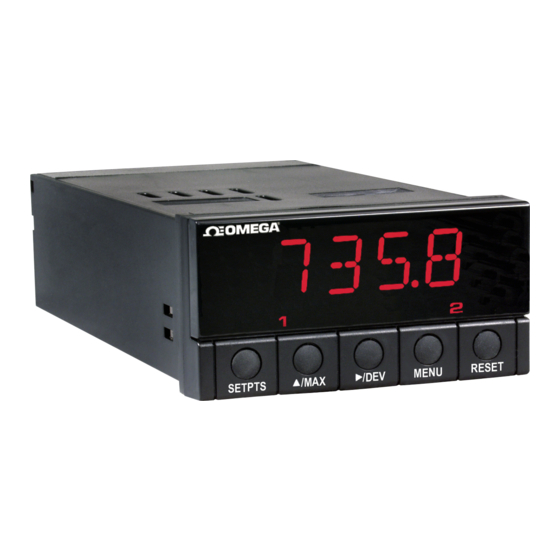
Page 11: Parts Of The Meter
SECTION 5. PARTS OF THE METER Figure 5-1 shows each part of the front of the meter. Table 5-1 gives a brief description of each part. •••• SETPTS MENU RESET Figure 5-1 Front Panel Illustration 1 - Setpoint 1 status 2 - Setpoint 2 status... - Page 12 Table 5-1 Front PanelPart Description ITEM Description -1.9.9.9. or 9.9.9.9. 4-digit 14 segment, 0.54” high LED display with programmable decimal point. SETPOINT LED These LEDs labled 1 and 2 display the status of setpoints 1 and 2. SETPTS Button This button functions only in the run mode. When the meter is in the run mode, press this button to sequentially recall the previous setpoint settings.
- Page 13 /DEV Button During the run mode press the /DEV button to display the deviation from setpoint 1. When configuring your setpoint values, press the /DEV button to scroll to the next digit. MENU Button In the run mode, press the MENU button to terminate the current measuring process and enter you into the configuration mode.
-
Page 14: Rear Of The Meter
5.2 REAR OF THE METER Figure 5-2 shows the connector label mounted at the top of the meter housing. Table 5-2 gives a brief description of each connector at the back of the meter. POWER & INPUT CONNECTIONS (RTD PROPORTIONAL) Figure 5-2 Connector Label (ac power with dc detail) -
Page 15: Table 5-2 Rear Connector Description
5.2 REAR OF THE METER (Continued) Table 5-2 Rear Connector Description Connector Description TB1-1 Setpoint 1: Normally open (N.O.1) connection TB1-2 Setpoint 1: Normally closed (N.C.1) connection TB1-3 Setpoint 1: Common (COM1) connection TB1-4 Setpoint 2: Normally open (N.O.2) connection TB1-5 Setpoint 2: Normally closed (N.C.2) connection TB1-6... -
Page 16: Setup
SECTION 6. SETUP 6.1 CONDITIONS REQUIRING DISASSEMBLY You may need to open up the meter for one of the following reasons: • To check or change the 115 or 230 Vac power jumpers. • To install or remove jumpers on the main board. 6.2 CONDITIONS REQUIRING DISASSEMBLY Disconnect the power supply before proceeding. -
Page 17: Figure 6-1 Main Board Power Jumpers (W1, W2, W3)
6.4 MAIN BOARD POWER JUMPERS (continued) Figure 6-1 Main Board Power Jumpers (W1, W2, W3) Figure 6-2 Main Board Jumper Positions Attach cable to P1. Figure 6-3 Upper Isolated Analog Outlook Option Board Installation... - Page 18 6.4 MAIN BOARD POWER JUMPERS (Continued) Refer to Figure 6-2. S2 jumpers are for sensor break indications: S2A jumper is not used S2B jumper is for positive sensor break (i.e. heating) S2C & S2D are not used S3 jumpers are used for the following (refer to Table 6-1): To enable or disable the front panel push-buttons To allow for an extremely low resistance load for analog output To disable the MENU button...
-
Page 19: Panel Mounting
6.5 PANEL MOUNTING CONNECTOR LABEL PRODUCT CASE LABEL GASKET FRONT BEZEL Figure 6-4 Meter - Exploded VIew 1. Cut a hole in your panel, as shown in Figure 6-4. For specific dimensions refer to Figure 6-5. 2. Insert the meter into the hole. -
Page 20: Sensor Input Connections
SECTION 7. SENSOR INPUT/ MAIN POWER CONNECTIONS 7.1 SENSOR INPUT CONNECTIONS Figures 7-1 through 7-3 describe how to connect your sensors. Figure 7-1 2-Wire RTD Input Connection Figure 7-2 3-Wire RTD Input Connection... -
Page 21: Figure 7-3 4-Wire Rtd Input Connection
7.1 SENSOR INPUT CONNECTIONS (continued) Figure 7-3 4-Wire RTD Input Connection 7.2 MAIN POWER CONNECTIONS Connect the ac main power connections as shown in Figure 7-4. Warning: Do not connect AC power to your device until you have completed all input and output connections. This device must only be installed by a specially trained electrician with corresponding qualifications. - Page 22 7.1 SENSOR INPUT CONNECTIONS (continued) Table 7-1 shows the wire color and respective terminal connections for both USA and Europe. Table 7-1 ac Power Connections WIRE COLORS AC POWER EUROPE ~ ac Line Brown Black ~ ac Neutral Blue White ~ ac Earth Green/Yellow Green...
-
Page 23: Analog And Relay Output Connections
7.3 ANALOG AND RELAY OUTPUT CONNECTIONS Figure 7-6 and 7-7 illustrates how to connect your analog and dual relay outputs at the rear of the meter. Figure 7-6 Analog Output Connections Figure 7-7 Relay Output Connections... -
Page 24: Figure 7-8 Transistor Output Connections
7.3 ANALOG AND RELAY OUTPUT CONNECTIONS (continued) HOUSING CONNECTOR P/N 9001111-02 CONNECTOR CRIMP CONTACT P/N 9001110 USE 22, 24 OR 26 AWG WIRES SUPPLIED BY CUSTOMER OUTPUT Figure 7-8 Transistor Output Connections Figure 7-9 Isolated Analog Output Connections (option) -
Page 57: Figure 25-1 Meter Dimensions
SECTION 25. SPECIFICATIONS (continued) 48,0 (1.89) 96,0 (3.78) FRONT BEZEL 20,3 (.80) RETAINER CASE REAR COVER TOP VIEW SIDE VIEW Figure 25-1 Meter Dimensions... -
Page 58: Input Type (Inpt)
SECTION 26. FACTORY PRESET VALUES Table 26-1. Factory Preset Values MENU ITEM FACTORY PRESET VALUES INPT Input Type: RTD.3 DEC.P Decimal Point Position: FFFF. RD.CF Reading Configuration: R.1=F (Fahrenheit) S1.CF Setpoint 1 Configuration: S.1=A (Setpoint is active above) S.2=U (Setpoint is unlatched) S.3=O (On/Off control) S2.CF Setpoint 2 Configuration:... -
Page 59: Ce Approvals Information
CE APPROVALS INFORMATION This product conforms to the EMC directive 89/336/EEC amended by 93/68/EEC, and with the European Low Voltage Directive 72/23/EEC. Electrical Safety EN61010-1:2001 Safety requirements for electrical equipment for measurement, control and laboratory. Double Insulation Pollution Degree 2 Dielectric withstand Test per 1 min •... - Page 60 NOTES...
- Page 61 NOTES...
- Page 62 NOTES...
- Page 63 Authorized Return (AR) number immediately upon phone or written request. Upon examination by OMEGA, if the unit is found to be defective, it will be repaired or replaced at no charge. OMEGA’s WARRANTY does not apply to defects resulting from any action of the purchaser, including but not limited to mishandling, improper interfacing, operation outside of design limits, improper repair, or unauthorized modification.
- Page 64 Where Do I Find Everything I Need for Process Measurement and Control? OMEGA…Of Course! Shop on line at www.omega.com TEMPERATURE Thermocouple, RTD & Thermistor Probes, Connectors, Panels & Assemblies Wire: Thermocouple, RTD & Thermistor Calibrators & Ice Point References Recorders, Controllers & Process Monitors...