
Related Manuals for Omega CN616TC1


Summary of Contents for Omega CN616TC1
- Page 1 User’s Gui d e Shop online at omega.com e-mail: info@omega.com For latest product manuals: www.omegamanual.info CN616 SerieS ⁄ DiN economical 6-Zone PiD Temperature Controllers...
- Page 2 Fax: (203) 359-7700 e-mail: info@omega.com For Other Locations Visit omega.com/worldwide The information contained in this document is believed to be correct, but OMEGA accepts no liability for any errors it contains, and reserves the right to alter specifications without notice.
-
Page 3: Table Of Contents
SECTION 1 INTRODUCTION Table of Contents 1.1 Description The CN616 Series is a second generation of industrial temperature SECTION PAGE controllers based on the field proven CN100 six zone temperature monitor/alarm system. Two models are available, standard and ex- SECTION 1 INTRODUCTION . -
Page 4: Models
Two Models are available: Underheat or Lo alarm is disabled until enabled zone reach and stay CN616TC1 - Standard Range Thermocouple over the setpoint for a set time. This is to prevent alarm when starting CN616TC2 - Extended Range Thermocouple from cold. - Page 5 To start setting a Profile, the main display shows the setpoint with All zones set for PID use the same PID parameters i.e.:- Proportional the first digit (MS) flashing. Set digits with the button. Then scroll through the display with the button.
-
Page 6: Section 2 Rs-232 Communications
SECTION 2 2.3 Operating Protocol for RS-232 Communications RS-232 COMMUNICATIONS The CN616 Controller is designed with standard RS-232 three wire serial NOTE: Minimum requirements to run RS-232 software is communication capabilities. Up to ten controllers can be parallel con- a PC computer with Windows 95. nected to a single PC. - Page 7 2.3.1 List of data transfer Codes Segment parameters:- Code “U” controller sends string Parameters:- Code “J” controller sends string Code “u” controller receive string Code “j” controller receive string Protocol from computer “ L3U”request for data for zone 1 Protocol from computer “...
-
Page 8: Rs-232 Pc Screens
2.4 RS-232 PC Screens PID parameters:- Code “K” controller sends string Six examples of program screens are shown below. Code “k” controller receive string Protocol from computer “ L3K” request for data “ L3k” + string of data Data string 22 characters long [9990] cycle time 99.90 seconds... -
Page 10: Section 3 Installation
SECTION 3 3.3 Outline Dimensions INSTALLATION 3.62" 3.1 Unpacking (92mm) 6.0" (152mm) Upon receipt of shipment, inspect the container and equipment for any signs of damage. Take particular note of any evidence of rough handling in transit. Immediately report any damage to the shipping agent. 3.62"... -
Page 11: Changing Line Voltage Setting
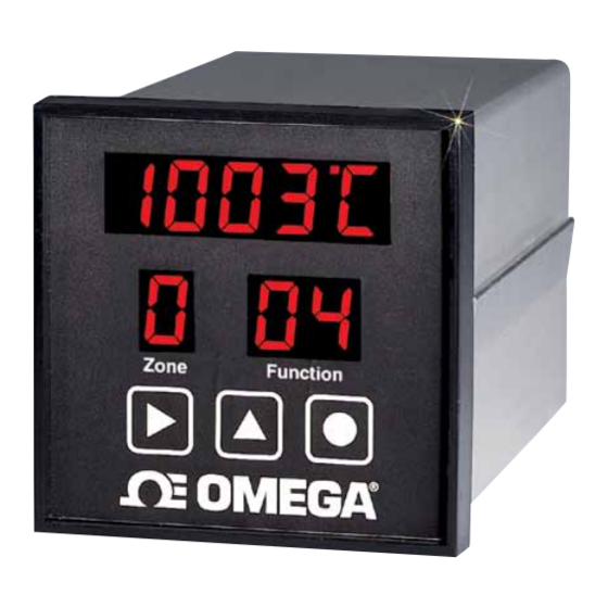
3.5 Changing Line Voltage Setting SECTION 4 Program the input line voltage by placing jumpers on the line plug as PARTS OF THE INSTRUMENT shown: LINE 120VAC Temperature\Setpoint Display Temperature Scale Selection 120V Jumper Placement: º LINE 240VAC Zone Setting Function Setting 240V Jumper Placement:... -
Page 12: Button Functions
4.2 Button Functions 4.3 Back of the Controller RS-232 Line Voltage There are three flatpad buttons provided and two combinations of Port LINE VOLTAGE and Jumpers RS-232 RELAY buttons for separate functions. 240V C IN OUT NC NO C Shift Button SPDT 120V 1. -
Page 13: Temperature/Setpoint Display
4.4 Temperature/Setpoint Display (Main Display) SECTION 5 “RUN” MODE During "RUN" MODE, the Main Display is used to monitor zone In the “RUN” Mode, the CN616 controls the temperature under the temperatures, check setpoints, and indicate ALARM conditions. program established during the last “SET” Mode. The “RUN” Mode is entered every time the controller is powered, after a power interruption, or 0 5 2 2 Temperature... -
Page 14: Section 6 Setup And Operation
6.1 Summary NOTE !! Controller setting is organized in 8 major functions and function groups To run Ramp & Soak [71 to 78] and their related functions, listed below. Unit must be set to run mode 51 or 52. [Fn 33] Number of segments must be more than 0 [Fn 74] Function 71... - Page 15 EXAMPLE: Function [99] Security Set High Alarm Setpoint [over setpoint] Security password protects all setup functions from accidental or unauthorized modifications. The security password is factory preset At 1011 and it can be changed only under RS232 computer pro- Action Buttons to use Display Before Display After gram.
- Page 16 [32]-[35] increment the flashing digit with the button When the To increment the flashing digit use the button desired function is displayed enter it with the button This will To advance to the next digit use the button display the desired function in the function display. To save the settings and return to function [71] use the button If the process times out the display will return “RUN”...
- Page 17 6.4.4 Function [34] ID for RS232 In function [36] the function display will show 36, the zone display will The ID code for the RS-232 is the identifying number for each unit show 1, and the upper display will show the current setpoint. connected through an RS-232 line to a computer.
- Page 18 6.6.3 Function [43] enable PID zone Function Group [73] PID Setup The enable PID zone Function allows selection of on/off or PID control The functions in group 73 allow the operator to examine and or change for individual zones. In function [43] the function display will show 43, the PID constants including those generated by autotuning.
-
Page 19: Segment Control
Function Group [75] Ramp and Soak 6.6.6 Function [46] Rate (99.99) minutes The Rate function allows the operator to examine and change the Function [75] controls segment functions [01] to [20] differential function of PID control. On entering function [75] the function display shows 75. The upper In function [46] function display will show 46, the zone display will be display will read 01 . -
Page 20: Set Autotune
Note !! Only the number of segments set in function [74] are allowed to Function [77] initiates unit autotuning. be set. After last segment is saved the unit segment setup will advance to On entering function [77] the function display reads 61. the next zone. -
Page 21: Start Profile
Open Collector Transistor Diagram for Output On entering function [78] the function display will read 78. External Power supply The upper display shows 30.00 mV setting. DC Z1 Z2 Z3 Z4 C Z5 Z5 Z6 Z6 Up to 40 VDC Enter the exact mV as measured by the millivolt meter. -
Page 22: Section 8 Specifications
SECTION 8 SPECIFICATIONS No. of Zones Input Range 0-40mV Standard/ 0-75mV Expanded Accuracy ±0.2% Range, ±2°C Resolution ±5uV Thermocouple Input selectable B,C,E,J,K,R,S,T Scale Selectable °C or °F Password protection Profiling [ramp / soak] 20 segments per loop Control outputs 6 [one per loop] Output rating :- Internal power 5V DC 10 Ma max External power... - Page 23 Controller power, 120 VAC setpoint indefinitely or until profile is started again. Drivers :- Solid State Relays ( Omega type SSRL240DC25) or equivalent. STANDARD MODE Setpoints for STANDARD MODE are set in function 36. INSTALLATION:- Each zone runs independently of other zones.
- Page 24 On page 29 of the Manual to load the following setpoints : Setup - Power the CN 616 controller Z1 - 400 º F Z2 - 500 º F 1. MODEL SELECTION. Z3 - 530 º F To comply with the requirements, the following model must be Z4 - 300 º...
- Page 25 EXAMPLE: Program Profile Segment Settings To run RAMP AND SOAK, CN616TC1 must be installed and set up as Set Profile Setpoint, Slope & Time for each Segment in each described in STANDARD MODE, then MODEL mode must be Zone (Large profiles are easily entered using the software.
- Page 26 To run RAMP AND SOAK CN616TC1 MODEL the mode must Enter => be set to 51 or 52[Function 71\31]. Number of segments must be set for each enabled zone[Function 74]. Setting the number of => Confirm Selection segments to “00” will set that zone to run in STANDARD mode.
- Page 27 Department will issue an Authorized Return (AR) number immediately upon phone or written request. Upon examination by OMEGA, if the unit is found to be defective, it will be repaired or replaced at no charge. OMEGA’s WARRANTY does not apply to defects resulting from any action of the purchaser, including but not limited to mishandling, improper interfacing, operation outside of design limits, improper repair, or unauthorized modification.
- Page 28 Where Do I Find Everything I Need for Process Measurement and Control? OMEGA…Of Course! Shop online at omega.com TEMPERATURE M U Thermocouple, RTD & Thermistor Probes, Connectors, Panels & Assemblies M U Wire: Thermocouple, RTD & Thermistor M U Calibrators & Ice Point References M U Recorders, Controllers &...