
Related Manuals for Omega CND3 Series


Summary of Contents for Omega CND3 Series
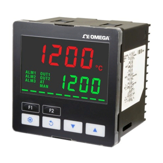
- Page 1 User’s Guide Shop online at omega.com e-mail: info@omega.com For latest product manuals: www.omegamanual.info CND3 Series Temperature Controller...
- Page 2 Fax: (203) 359-7700 e-mail: info@omega.com For Other Locations Visit omega.com/worldwide The information contained in this document is believed to be correct, but OMEGA accepts no liability for any errors it contains, and reserves the right to alter specifications without notice.
- Page 3 2018/3/5 CND3 Series Temperature Controller Instruction Sheet Precaution Warning! Please comply with safety precautions in the manual. Failure to do so may cause controller or peripheral products malfunction, or even result in serious harm such as fire, electrical injury or other damages.
- Page 4 Note: Not all combinations may be available Check website under "All Models" to see list of available models. ...
- Page 5 0: None, 1: Event Input3, 2: RS-485 Communication EVENT inputs/ CT function (optional) 1 0: None, 1: Event Input2, 2: CT measure input2. EVENT inputs/ CT function (optional) 2 0: None, 1: Event Input1, 2: CT measure input1. EVENT inputs/ CT function (optional) 3 ...
- Page 6 ALARM2 HIGH: Upper limit alarm 2 (display according to the setting in ALARM mode) ALARM2 LOW: Lower limit alarm 2 (display according to the setting in ALARM mode) ALARM3 HIGH: Upper limit alarm 3 (set OUT2 to ALARM mode and it will display according to the setting in ALARM mode) ALARM3 LOW: Lower limit alarm 3 (set OUT2 to ALARM mode and it will display according to the setting in ALARM mode)
- Page 7 ALARM3 DELAY: Set up Alarm 3 delay (refer to “Alarm Outputs” ) (display when OUT2 is set to ALARM mode) PV Color Change Function: Select the alarm to change PV display color. (refer to "Alarm Outputs") 2PID change temperature (display on 2PID control mode) 2PID reset temperature (display on 2PID control mode) REMOTE TYPE: Set up Remote type (display when is set to REMO mode)
- Page 8 PV OFFSET: Adjust input compensation of PV PV GAIN: Adjust input gain of PV 0.000 SV SLOPE: Set up rising slope (when CRTS = SLOP) ANALOG OUT1 MAX.: Adjust upper limit compensation for analog Output 1 (1scale = 1μA; 1scale = 1mV) ANALOG OUT1 MIN.: Adjust lower limit compensation for analog Output 1 (1 scale = 1μA;...
- Page 9 Initial Start-up Setting When setting up CND3 for first time, press key for more than 3 seconds till the screen display and select according to your temperature sensor type. Please be aware that a selection of wrong model would cause PV temperature display error. (Refer to the chart below) When setting up the temperature sensor type by using RS-485, write your value (range 0~19) into register 1004H.
- Page 10 Value + Compensation Value. For example: Measure Value=25.0; Compensation = 1.2. After applying to the Compensation equation PV=26.2. Linear Compensation Gain (setting range = -0.999~0.999). Linear Compensation Gain Calculation equation: PV = Measure Value* (1 + Gain/1.000) + Compensation. For example: Measure Value=25.0;...
- Page 11 R: RETRANSMISSION output Selection for Heating/Cooling/Alarm/Dual Loop Output Control CND3 series offers 1 set of Output Control (OUT1) that is built-in internally and 2 sets of Alarm Output(ALARM1 and ALARM2). User can also purchase a 2 set of Output Control (OUT2) or a 3 set of Alarm Output (ALARM3).
- Page 12 Output of when in PID control mode (Ctrl=PID): Heating Cooling Heating Cooling Set Point Set Point When the controller is in PID control and dual loop output mode, sets the P value of the 2nd set of PID. The 1st set of PID is generated when TUNE= AT, but user can also manually sets the PID value.
- Page 13 the start status, the program will start running from the initial pattern and initial step. When setting control is in pause control and temperature is controlled at the setting value before the stop, by re-selecting the start status, the program will start running from the step where the program was paused and carry out the remaining part.
- Page 14 limit of input)*(Remote input value - lower limit of Remote input)/( higher limit of Remote input - lower limit of Remote input) – Remote lower limit of input) Set parameter in 【Initial Setting Mode】 Note: This option is only available when a Remote board is inserted. If the Remote type is of analog current, the JP in the Remote board must be shorted (using a short cap).
- Page 15 PID Mode: When set for heating or cooling, the program performs PID operation via input temperature and setting temperature, with the operation result output for the temperature control. A PID parameter and control period must be set for this function; these parameters can also be generated automatically via auto-tuning (AT).
- Page 16 or C (Cooling) Set output %: in parameter 【Operation Mode】, PV screen displays “oUt‘x’”, ‘x’ is 1 (output 1) or 2 (output 2) FUZZY Mode: This comprises 2 parts: PID parameters and Fuzzy exclusive parameters. Since Fuzzy control is calculated based ...
- Page 17 output 2 reverse setting: Set a value corresponding to Y position by parameter in 【Initial Setting Mode】, such as xxYx (Y can be 0 or 1; 0: forward; 1: reverse) Limits controlling the output range Maximum and minimum output can be limited; if the original maximum control output is 100% and the minimum control output is 0%, you may set the maximum control output to 80% and the minimum control output to 20%.
- Page 18 Limits of temperature ranges Different input sensors have different application ranges (e.g.: J type factory setting is -100 ~ 1200℃), adjust parameters (upper limit) / (lower limit) in Initial Setting Mode. If lower limit is altered to 0 and upper limit is altered to 200, the limit function will be enabled in the following conditions: When setting the SV value, the limits may set for 0~200℃...
- Page 19 M215 M315 M115 M216 M316 M116 M217 M317 M117 M218 M318 M118 M219 M319 M119 M220 M320 M120 M221 M321 M121 M222 M322 M122 M223 M323 M123 M224 M324 M124 M225 M325 M125 M226 M326 M126 M327 M227 M228 M328 M229 M329 M230...
- Page 20 d、 Alarm Reverse Output Setting: An alarm output can be set for NC( Normal close) or NO(Normal Open). e、 Alarm Peak Record Setting: For recording the peak value of the alarm signal. Alarm Type Alarm Output Operation Value Alarm function disabled Deviation upper- and lower-limit: This alarm output operates when PV value is higher than the setting value SV+(AL-H) or lower than the setting value SV-(AL-L).
- Page 21 (When Y=0: reverse, Y=1: forward) To set Alarm 3: Alarm 3 function is available when an output board is connected to Output 2. Use the parameter in【Initial Setting Mode】, press the key ▲ or ▼ to select for the following control output items: H1H2, C1H2… H1A2(H defines heating, C defines cooling, 1 indicates Output1, 2 indicates Output2 , A indicates Alarm3).
- Page 22 2nd output group Output value read and write of 1012H Unit is 0.1%, write operation is valid under manual tuning mode only. Output 1 Output value read and write of 1013H Unit is 0.1%, write operation is valid under manual tuning mode only. Output 2 1016H Temperature regulation value...
- Page 23 1106H AT Control 0: AT(Auto-tune), 1: ST(Self-tune) 1107H Remote Input Reverse Setting 0: forward, 1: reverse 1108H Alarm 1 Function Selection Bit3: Peak Record, Bit2: Hold Enable, Bit1: Output Reverse, Bit0: Standby Enable 1109H Alarm 2 Function Selection Bit3: Peak Record, Bit2: Hold Enable, Bit1: Output Reverse, Bit0: Standby Enable 110AH Alarm 3 Function Selection Bit3: Peak Record, Bit2: Hold Enable, Bit1: Output Reverse, Bit0: Standby Enable...
- Page 24 CMD 0 ‘3’ ‘2’ CMD 0 ‘3’ ‘2’ CMD 0 ‘6’ ‘5’ CMD 0 ‘6’ ‘5’ ‘1’ ‘0’ ‘0’ ‘0’ ‘1’ ‘0’ ‘1’ ‘0’ Number of data ‘0’ ‘8’ ‘4’ ‘2’ ‘0’ ‘8’ ‘0’ ‘8’ Starting data Starting data Starting data (count by byte) address address...
- Page 28 OMEGA Engineering, Inc. 800 Connecticut Ave. Suite 5N01 Norwalk, CT 06854 USA Customer Service: 1-800-622-2378 (USA & Canada only) Engineering Service: 1-800-872-9436 (USA & Canada only)