Table of Contents
Advertisement
www.nordictrack.com
Model No. NTEL91211.0
USER’'S MANUAL
Serial No.
Write the serial number in the space
above for reference.
Serial Number Decal
QUESTIONS?
If you have questions, or if parts
are damaged or missing, DO NOT
CONTACT THE STORE; please
contact Customer Care.
IMPORTANT: Please register this
product (see the limited warranty
on the back cover of this manual)
before contacting Customer Care.
CALL TOLL-FREE:
1-800-TO-BE-FIT
(1-800- 862-3348)
Mon.––Fri. 6 a.m.––6 p.m. MT
Sat. 8 a.m.––4 p.m. MT
ON THE WEB:
www.nordictrackservice.com
CAUTION
Read all precautions and instruc-
tions in this manual before using
this equipment. Keep this manual
for future reference.
Advertisement
Table of Contents

Related Manuals for NordicTrack NTEL91211.0


Summary of Contents for NordicTrack NTEL91211.0
- Page 1 Model No. NTEL91211.0 USER’’S MANUAL Serial No. Write the serial number in the space above for reference. Serial Number Decal QUESTIONS? If you have questions, or if parts are damaged or missing, DO NOT CONTACT THE STORE; please contact Customer Care.
-
Page 2: Table Of Contents
If a decal is missing or illegible, see the front cover of this manual and request a free replacement decal. Apply the decal in the location shown. Note: The decal(s) may not be shown at actual size. NORDICTRACK is a registered trademark of ICON IP, Inc. -
Page 3: Important Precautions
IMPORTANT PRECAUTIONS WARNING: To reduce the risk of serious injury, read all important precautions and instructions in this manual and all warnings on your elliptical before using your elliptical. ICON assumes no responsibility for personal injury or property damage sustained by or through the use of this product. -
Page 4: Before You Begin
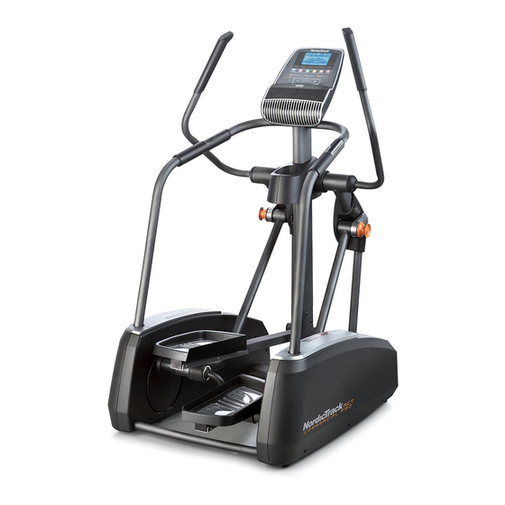
BEFORE YOU BEGIN Thank you for selecting the revolutionary reading this manual, please see the front cover of this NORDICTRACK ® ACT COMMERCIAL PRO elliptical. manual. To help us assist you, note the product model The ACT COMMERCIAL PRO elliptical provides an number and serial number before contacting us. -
Page 5: Part Identification Chart
PART IDENTIFICATION CHART Use the drawings below to identify the small parts needed for assembly. The number in parentheses below each drawing is the key number of the part, from the PART LIST near the end of this manual. The number following the key number is the quantity needed for assembly. -
Page 6: Assembly
ASSEMBLY •• Assembly requires two persons. •• In addition to the included tool(s), assembly requires the following tools: •• Place all parts in a cleared area and remove the one Phillips screwdriver packing materials. Do not dispose of the packing materials until you complete all assembly steps. - Page 7 2. Identify the Frame Cover (54), and orient it as shown. Slide the Frame Cover onto the Frame (1), and press the posts on the Frame Cover into the indicated holes in the Frame. Next, orient the Upright (2) as shown. While a second person holds the Upright near the Frame (1), connect the Upper Wire (81) to the Lower Wire (82).
- Page 8 4. Identify the Right Handrail (5), which is marked with an ““R”” on the underside. Orient the Right Handrail as shown. Avoid pinching the Heart Rate Wire Tie While a second person holds the Right Handrail Wires (77, 92) (5) near the Upright (2), tie the indicated wire tie to the Right Heart Rate Wire (92).
- Page 9 6. Using a small plastic bag to keep your fingers clean, apply a generous amount of the included grease to the right axle on the Upright (2). Next, identify the Right Handlebar Leg (13), which is marked with an ““R”” sticker, and orient it Grease as shown.
- Page 10 8. Apply a small amount of grease to the axle on the Left Pedal Arm (14). Position the Left Handlebar Leg (12) as shown. Then, insert the Left Pedal Arm (14) into the Left Handlebar Leg. Attach the Left Pedal Arm (14) with an M10 x 20mm Screw (61), a Pedal Axle Cover (39), and Grease an M10 Washer (64).
- Page 11 10. Identify the Right Large Rail Cover (93), and orient it as shown. Press the Right Large Rail Cover into the Right Outer Shield (17). Next, identify the Right Small Rail Cover (7), and orient it as shown. Press the Right Small Rail Cover into the Right Large Rail Cover (93) and into the Right Outer Shield (17).
- Page 12 12. While a second person holds the Console (3) near the Upright (2), connect the four wires on Avoid pinching the Console to the Upper Wire (81), the two the wires Heart Rate Wires (92, 77), and the Extension Wire (102). Insert the excess wire into the Upright.
-
Page 13: The Chest Heart Rate Monitor
THE CHEST HEART RATE MONITOR HOW TO PUT ON THE HEART RATE MONITOR •• Do not expose the heart rate monitor to direct sun- light for extended periods of time; do not expose it to The heart rate temperatures above 122° F (50° C) or below 14° F monitor consists of (-10°... -
Page 14: How To Use The Elliptical
HOW TO USE THE ELLIPTICAL HOW TO PLUG IN THE POWER ADAPTER HOW TO LEVEL THE ELLIPTICAL IMPORTANT: If the elliptical has been exposed to If the elliptical rocks cold temperatures, allow it to warm to room tem- slightly on your perature before you plug in the power adapter. - Page 15 HOW TO EXERCISE ON THE ELLIPTICAL To mount the elliptical, hold the handlebars and step onto the pedal that is in the lower position. Then, step Handlebars onto the other pedal. Push the pedals until they begin to move with a continuous motion. Note: The pedals can turn in either direction.
- Page 16 CONSOLE DIAGRAM FEATURES OF THE CONSOLE When you use the manual mode of the console, you can change the resistance of the pedals with the touch The advanced console offers an array of features of a button. designed to make your workouts more effective and enjoyable.
- Page 17 HOW TO ACTIVATE THE CONSOLE 4. Follow your progress with the display. The included power adapter must be used to operate The display can show the following workout the elliptical. See HOW TO PLUG IN THE POWER information: ADAPTER on page 14. When the power adapter is plugged in, the display will turn on and the console will be ready for use.
- Page 18 Stride——This display mode will show the total num- When a wireless iFit Live mod- ber of strides you have pedaled. ule is connected, the wireless symbol at the top of the display Time——When the manual mode is selected, this will show the strength of your display mode will show the elapsed time.
- Page 19 If the display does not show your heart rate, make HOW TO USE AN ONBOARD WORKOUT sure that your hands are positioned as described. Be careful not to move your hands excessively or 1. Begin pedaling or press any button on the to squeeze the contacts tightly.
- Page 20 During the If the resistance level for the current segment is workout, the too high or too low, you can manually override profiles on the setting by pressing the Resistance buttons. the speed IMPORTANT: When the current segment of the tab will show workout ends, the pedals will automatically your progress.
- Page 21 HOW TO USE AN IFIT LIVE WORKOUT 5. Select an iFit Live workout. Note: To use an iFit Live module, you must have To select an iFit Live workout, press one of the iFit access to a computer with an internet connection and a Live buttons.
- Page 22 7. Follow your progress with the display. HOW TO USE THE SOUND SYSTEM See step 4 on page 17. To play music or audio books through the console sound system while you exercise, plug one end of your The My Trail tab will show a map of the trail you are audio cable into the jack on the console.
- Page 23 HOW TO CHANGE CONSOLE SETTINGS If no module is connected, the display will show the words NO IFIT MODULE. If no module is con- The console features a user mode that allows you to nected, go to step 10. view usage information, select a unit of measurement, and adjust the contrast level of the display.
-
Page 24: Fcc Information
FCC INFORMATION This equipment has been tested and found to comply with the limits for a Class B digital device, pursuant to part 15 of the FCC Rules. These limits are designed to provide reasonable protection against harmful interference in a residential installation. This equipment generates, uses, and can radiate radio frequency energy and, if not installed and used in accordance with the instructions, may cause harmful interference to radio communications. -
Page 25: Maintenance And Troubleshooting
MAINTENANCE AND TROUBLESHOOTING I nspect and tighten all parts of the elliptical regularly. Next, locate the Reed Switch (86). Turn the Pulley (53) Replace any worn parts immediately. until a Magnet (88) is aligned with the Reed Switch. To clean the elliptical, use a damp cloth and a small amount of mild soap. -
Page 26: Exercise Guidelines
EXERCISE GUIDELINES Burning Fat——To burn fat effectively, you must exer- WARNING: cise at a low intensity level for a sustained period of Before beginning this time. During the first few minutes of exercise, your or any exercise program, consult your physi- body uses carbohydrate calories for energy. -
Page 27: Part List
PART LIST Model No. NTEL91211.0 R0212A Key No. Qty. Description Key No. Qty. Description Frame Crank Spacer Upright Crank Cover Console Adjustment Pin Left Handrail Crank Bracket Bearing Right Handrail Wheel Left Small Rail Cover Leveling Foot Right Small Rail Cover... - Page 28 Key No. Qty. Description Key No. Qty. Description Right Large Rail Cover Idler Bolt Handle Bottom Receiver/Wire Aluminum Cover M6 Washer M4 x 12mm Round Head Screw Flywheel Axle Pivot Screw Belt Adjustment Screw M4 x 16mm Bright Screw Heart Rate Monitor/Strap Left Pedal ––...
-
Page 29: Exploded Drawing
EXPLODED DRAWING A Model No. NTEL91211.0 R0212A... - Page 30 EXPLODED DRAWING B Model No. NTEL91211.0 R0212A...
- Page 31 EXPLODED DRAWING C Model No. NTEL91211.0 R0212A...
-
Page 32: Ordering Replacement Parts
ORDERING REPLACEMENT PARTS To order replacement parts, please see the front cover of this manual. To help us assist you, be prepared to provide the following information when contacting us: •• the model number and serial number of the product (see the front cover of this manual) ••...