Follett 25 Installation, Operation And Service Manual
25 and 50 series ice and water dispensers
Hide thumbs
Also See for 25:
- Installation, operation & service manual (32 pages) ,
- Installation, operation and service manual (36 pages)
Table of Contents
Advertisement
Order parts online
www.follettice.com
25CR400A/W 50CR400A/W
Installation, Operation and Service Manual
25CT400A/W
50CT400A/W
™
(shown with SensorSAFE
accessory)
Following installation, please forward this manual
to the appropriate operations person.
801 Church Lane • Easton, PA 18040, USA
Toll free (877) 612-5086 • +1 (610) 252-7301
www.follettice.com
Ice and Water Dispensers
25HT400A/W
(shown with SensorSAFE accessory)
25HR400A/W 50HR400A/W
25 and 50 Series
50HT400A/W
25FB400A/W
50FB400A/W
(shown with SensorSAFE accessory)
208596R11
Advertisement
Table of Contents

Related Manuals for Follett 25


Summary of Contents for Follett 25
- Page 1 25 and 50 Series Ice and Water Dispensers Order parts online Installation, Operation and Service Manual www.follettice.com 25CT400A/W 50CT400A/W 25HT400A/W 50HT400A/W ™ (shown with SensorSAFE accessory) (shown with SensorSAFE accessory) 25HR400A/W 50HR400A/W 25FB400A/W 50FB400A/W 25CR400A/W 50CR400A/W (shown with SensorSAFE accessory) Following installation, please forward this manual to the appropriate operations person.
-
Page 2: Table Of Contents
Troubleshooting SensorSAFE board and sensors .....................20 Disassembly and replacement instructions .......................22 Thermostat locations ..............................24 Parts ....................................25 Dispenser exterior ..............................25 Dispense chute and splash panel areas – lever models ...................26 Electrical box – lever models .............................27 Dispense chute and splash panel areas – SensorSAFE models ................28 Electrical box –... -
Page 3: Before You Begin
Welcome to Follett Follett equipment enjoys a well-deserved reputation for excellent performance, long-term reliability and outstanding after-the-sale support. To ensure that this equipment delivers that same degree of service, we ask that you review the installation portion of this manual before beginning to install the unit. Our installation instructions are designed to help you achieve a trouble-free installation. -
Page 4: Specifi Cations
Water temp +90 F/+32 C max. +40 F/+4 C min. (best performance below +70 F/+21 C) Water pressure 70 P.S.I. max. 10 P.S.I. min. Plumbing 25/50 CR with 25/50 HR with 25/50 CT with 25/50 HT with 25/50 FB RIDE... -
Page 5: Field Wiring
Field wiring for countertop and wall mount dispensers with RIDE technology ice machines All fi eld wiring must be installed in accordance with NEC and local electrical codes. Field wiring diagram is intended only to aid electrician or technician in understanding how equipment works. Model Electrical connection Circuits required... -
Page 6: Installing Freestanding Dispensers
Field Wiring diagrams (For installations requiring hard-wiring equipment) Freestanding dispensers, countertop and wall mount dispensers with integral ice machines IMPORTANT Electric Power Source Standard electrical - 115V, 1 Ph, 60 Hz, FIELD WIRING DIAGRAM IS max. fuse size 20 amps INTENDED TO AID ELECTRICIAN OR TECHNICIAN IN UNDERSTANDING HOW EQUIPMENT WORKS. -
Page 7: Installation
Installation procedure Before you begin • All dispensers must be installed level in both directions to ensure proper operation • Required ventilation and recommended service clearances: • Countertop and wall mount models with RIDE ice machine (25CR400A/W, 25HR400A/W, 50CR400A/W, 50HR400A/W) — none. - Page 8 (267mm) (C) 3/4" MPT icemaker drain location 6.75" (water-cooled only) 31.5" (171mm) (800mm) 15.125" (384mm) 10.25" (259mm) 3.125" 3.125" (79mm) (79mm) (B) 3/4" MPT icemaker drain location (air-cooled only) Verify that water sensor tabs are immersed in water in reservoir.
-
Page 9: Installing Countertop Dispensers
Installing countertop dispensers Dispensers with top mount ice machines cannot be mounted on legs. They must be bolted to counter. Use gloves when lifting ice machine to protect hands from sheet metal edges. 1. Position dispenser in desired location, mark Fig. - Page 10 5. If power is to be supplied through counter cut-out, complete steps 6-9. If power is to be supplied through rear of dispenser, proceed to step 10. 6. Temporarily remove rear access panel (Figs. 4 and 5) from rear of dispenser. 7.
-
Page 11: Installing Wall Mount Dispensers
Installing wall mount dispensers Wall and fasteners must be of sufficient strength to carry weight of unit. Hardware for this is not included. 1. Install supplied wall bracket with six 3/8" diameter fasteners as shown in Fig. 7. Note: Three holes are available at each fastening site to allow capture of studs/support within wall. Steps 2 - 3 are required for models with integral ice machine only (25HT400A/W and 50HT400A/W). - Page 12 16" 20.875" (530mm) (406mm) wall stud 3/8" fasteners filler strip 25HT400A/W 17.8" 25HR400A/W 9.5" (241mm) (445mm) 25.5" 50HT400A/W 16" (648mm) wall bracket 11.5" (292mm) (406mm) 50HR400A/W wall stud 29.5" 25HT400A/W (749mm) 9.5" (241mm) 3/8"...
-
Page 13: Installing Ride ® Technology Ice Machines
Installing RIDE ice machines Models 25CR400A/W, 50CR400A/W, 25HR400A/W, 50HR400A/W See Ice machine Installation Manual (form #208600) for critical installation instructions for RIDE ice machines. Failure to comply with these instructions will result in poor performance and void warranty. 1. Install RIDE ice machine following instructions in ice machine manual. 2. -
Page 14: Installing Top Mount Ice Machines
Installing top mount ice machines Models 25CT400A/W, 50CT400A/W, 25HT400A/W, 50HT400A/W Dispensers with top mount ice machines cannot be mounted on legs. They must be bolted to counter. Use gloves when lifting ice machine to protect hands from sheet metal edges. 1. -
Page 15: User Information
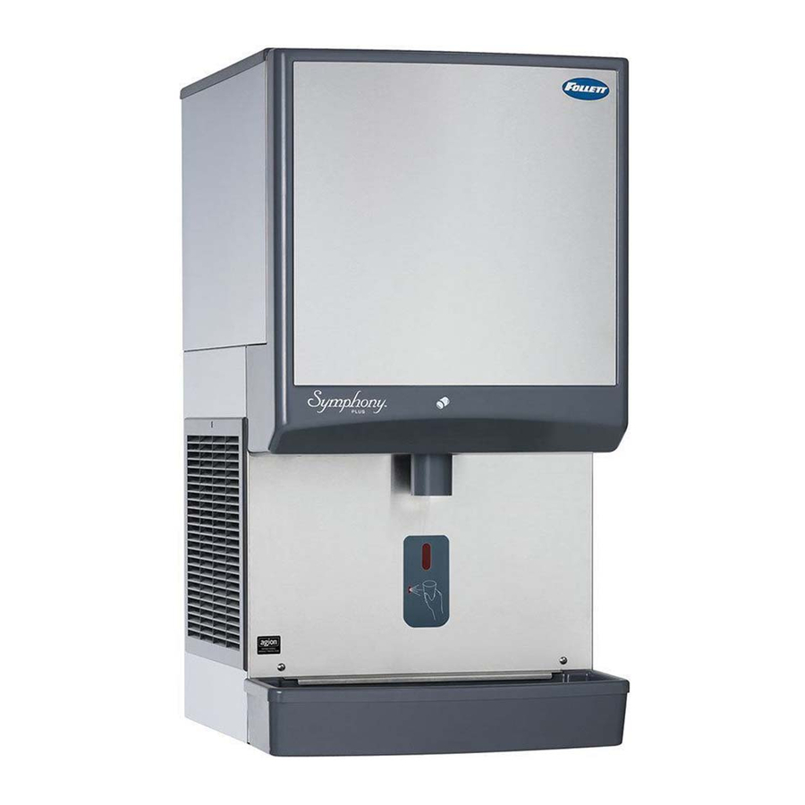
How the dispenser works Follett’s 25 and 50 automatic load ice and water dispensers receive ice from Follett’s 400 lb (181kg)/day ice machine located in the dispenser base, in the cabinet top or in a remote location up to 20 ft (6m) away. Ice produced is stored in the bin section of the dispenser. -
Page 16: Cleaning/Descaling And Sanitizing
Cleaning/descaling and sanitizing Periodic cleaning/descaling and sanitizing of Follett’s ice and water dispenser and ice machine system is required to ensure peak performance and delivery of clean, sanitary ice. The recommended cleaning procedures that follow should be performed at least as frequently as recommended and more often if environmental conditions dictate. Cleaning of the condenser can usually be performed by facility personnel. - Page 17 CAUTION! § Wear rubber gloves and safety goggles (or face shield) when handling cleaner or sanitizer mixtures. § Use only Follett approved cleaners. § It is a violation of Federal law to use Solution A or Solution B in a manner inconsistent with their labeling. §...
-
Page 18: Service Information
Service information Wiring diagrams How unit works — lever models The dispense wheel motor is energized through the power and ice dispense switches. The water solenoid valve is energized through the power and water dispense switches. The ice machine receives the bin signal through the power switch, the normally closed bin thermostat and the ice machine switch. -
Page 19: Wiring Diagram - Sensorsafe Models
How unit works — SensorSAFE models SensorSAFE models provide “touchless” ice and water dispensing. When a container is placed within the actuation zone below the ice or water chute on SensorSAFE dispenser models, an infrared signal refl ects off the container and is detected by the sensor. -
Page 20: Dispenser Troubleshooting
Dispenser troubleshooting Disconnect power to dispenser and ice machine before putting hands or arms in storage area, or attempting any repair or service to equipment. Before calling for service: • Check that there is ice in dispenser bin area • Check that all switches and circuit breakers are on •... - Page 21 Problem: Does not dispense ice or water Action LED Status Solution ICE/WTR Check circuit breakers and power switch; restore Check LEDs on control power or replace defective switch board Depress clean switch located under left side of front cover to return board to normal operation Troubleshoot appropriate lens/sensor and replace if Place cup under drop required (see Lens/Sensor Troubleshooting below)
-
Page 22: Disassembly And Replacement Instructions
Disassembly and replacement instructions Dispense chute removal 1. Remove dispenser front cover. 2. Slide plastic dispense chute cover up and out to remove. 3. Pull out four white plastic fasteners and remove dispense chute. Dispense wheel removal and installation Note: Models with top mount ice machines require removal of ice machine before removing wheel. 1. -
Page 23: Ice Transport Tube Replacement
Ice transport tube replacement Models 25FB400A/W, 50FB400A/W, 25CR400A/W, 50CR400A/W Correct installation of ice transport tube is critical to RIDE ice machine performance. Replacement ice transport tubes for RIDE ice machines must be insulated and run continuously from ice machine to dispenser with no dips or bends with a radius of less than 6"... -
Page 24: Thermostat Locations
Thermostat locations Thermostat locations – 25CT400A/W, 25HT400A/W, 50CT400A/W, 50HT400A/W ice deflector bracket assembly rubber grommet ice level control stat ice level control stat bin thermostat control box assembly hopper assembly control box assembly .75" ice level (20mm) control stat Hand bend cap tube end to approx. -
Page 25: Parts
Parts Dispenser exterior Reference Description Part # Cover, top front, 25 CT & HT units 502679 Cover, top front, 50 CT & HT units 502680 Cover, top front, 25 CR, HR & FB 502677 Cover, top front, 50 CR, HR & FB... -
Page 26: Dispense Chute And Splash Panel Areas - Lever Models
Dispense chute and splash panel areas (lever models) — Serial Number E08194 and above Reference Description Part # Fastener, 10-32 x 3/8" stainless steel 00982421 Tube, water station 502356 Cover, dispense chute 502681 Switch, dispense, lever actuated (includes 501841) 502359 Bracket, lever and water solenoid 01039635 Bracket, lever... -
Page 27: Electrical Box - Lever Models
Dispense chute and splash panel areas (lever models) — Serial Numbers below E08193 Reference Description Part # Fastener, dispense chute bracket 502057 Tube, water station 502356 Cover, dispense chute 502681 Switch, dispense, ice, lever actuated (includes 501841) 502359 Switch, dispense, water, lever actuated (includes 501841) 502359 Bracket, chute (includes fasteners 502057) 502247... -
Page 28: Dispense Chute And Splash Panel Areas - Sensorsafe Models
Dispense chute and splash panel areas (SensorSAFE) — Serial Number E08194 and above Reference Description Part # Cover, dispense chute 502681 ® Chute, ice (with Agion antimicrobial product protection 01041201 Chute, water (with Agion) 01042266 ® Not shown Chute, ice (with Agion antimicrobial product protection ), wall hung 01040005... - Page 29 Dispense chute and splash panel areas (SensorSAFE) — Serial Numbers below E08193 Reference Description Part # Fastener, dispense chute bracket 502057 Cover, dispense chute (includes labels) 502681 Chute and funnel, ice 502689 Chute, water 502249 Not shown Chute and funnel, ice, wall mount, no drain pan 00129908 Not shown Chute, water, wall hung, no drain pan...
-
Page 30: Electrical Box - Sensorsafe Models
Electrical box (front view) – SensorSAFE models Reference Description Part # Thermostat, bin level 500514 Switch, dispenser power 502209 Switch, ice machine bin signal 502209 Control board, SensorSAFE 502242 Not shown Clean switch, SensorSAFE 502359 Not shown Boot, clean switch 501841 Wheel motor and drive system Reference... -
Page 31: Hopper Components
Hopper components Top view – all top mounted units Top view – freestanding and RIDE units Ice tube bracket – side view – Ice tube bracket – side view freestanding & RIDE units – all top mounted units Reference Description Part # Baffle, ice 501608... -
Page 32: Chilled Water Components
Ice transport tube insulation (RIDE units only) - sold by the foot 501176 Not shown Ice transport tube assembly (50 FB units) 502328 Not shown Ice transport tube assembly (25 FB units) 502329 Not shown Ice transport tube assembly (top mount units) 502697 Chilled water components... -
Page 33: Countertop Dispenser Plumbing Connections
Countertop dispenser plumbing connections Mounting plate fi ttings Reference Description Part # Strainer 00136663 Valve, water shut-off 502222 Drain tube assembly 502685 Fitting, water inlet with mounting plate 502100 Drain pan 502682 Elbow 502718 Tee, water inlet 502433 Bulkhead fi ttings Reference Description Part #... - Page 34 25CT/HT/CR/HR/FB and 50CT/HT/CR/HR/FB...
- Page 35 25CT/HT/CR/HR/FB and 50CT/HT/CR/HR/FB...
- Page 36 SensorSAFE and Symphony are trademarks of Follett Corporation. Follett and RIDE are registered trademarks of Follett Corporation, registered in US. 801 Church Lane • Easton, PA 18040, USA Toll free (877) 612-5086 • +1 (610) 252-7301 208596R11 www.follettice.com © Follett Corporation 8/13...