Follett Symphony Plus 50 Series Installation, Operation And Service Manual
Ice and water dispensers
Hide thumbs
Also See for Symphony Plus 50 Series:
- Installation, operation and service manual (60 pages) ,
- Operation and service manual (36 pages) ,
- Installation manual (17 pages)
Table of Contents
Advertisement
Quick Links
Symphony Plus
25 and 50 Series
™
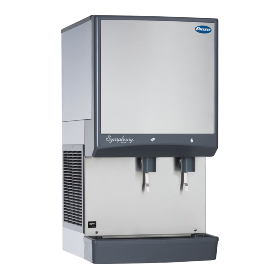
Ice and Water Dispensers
25CI425A/W, 25HI425A, 50CI425A/W, 50HI425A
Installation, Operation and Service Manual
25/50CI425A/W-SI Countertop
25/50CI425A/W-LI Countertop Ice-only
25/50HI425A-SI Wall Mount
Ice-only Dispenser with
Dispenser with Lever Dispensing
Ice-only Dispenser with
SensorSAFE™ Dispensing
SensorSAFE Dispensing
25/50CI425A/W-S Countertop Dispenser
25/50CI425A/W-L Countertop Dispenser
25/50HI425A-S Wall Mount Dispenser
with SensorSAFE™ Dispensing
with Lever Dispensing
with SensorSAFE Dispensing
Following installation, please forward this manual
to the appropriate operations person.
801 Church Lane • Easton, PA 18040, USA
Order parts online:
Toll free (877) 612-5086 • +1 (610) 252-7301
www.follettice.com
www.follettice.com
01033679R04
Advertisement
Table of Contents

Related Manuals for Follett Symphony Plus 50 Series


Summary of Contents for Follett Symphony Plus 50 Series
- Page 1 Symphony Plus 25 and 50 Series ™ Ice and Water Dispensers 25CI425A/W, 25HI425A, 50CI425A/W, 50HI425A Installation, Operation and Service Manual 25/50CI425A/W-SI Countertop 25/50CI425A/W-LI Countertop Ice-only 25/50HI425A-SI Wall Mount Ice-only Dispenser with Dispenser with Lever Dispensing Ice-only Dispenser with SensorSAFE™ Dispensing SensorSAFE Dispensing 25/50CI425A/W-S Countertop Dispenser 25/50CI425A/W-L Countertop Dispenser...
-
Page 2: Table Of Contents
Welcome to Follett........ -
Page 3: Welcome To Follett
. § Follett recommends a Follett water filter system be installed in the ice machine inlet water line (standard capacity #00130299, high capacity #00978957, carbonless high capacity #01050442) . -
Page 4: Specifications
Specifications Countertop Front View Right Side View Rear View 21" (53.4 cm) 24" (61 cm) 3/8" FPT condenser inlet (water- cooled only) 3/8" FPT 25CI400A/W condenser 36" outlet (water- (91.5 cm) cooled only) 3/4" FPT drain 50CI400A/W 40" (101.6 cm) NEMA 10.5"... -
Page 5: Electrical
Electrical § 115 V, 60 Hz, 1 phase, 11 .0A § Connect to a 15A dedicated circuit . § Furnished with 7 ft (2 m) power cord with a 90° NEMA hospital grade 5-15 plug . Ambient Air temp* 100 F/38 C Max . 50 F/10 C Min . -
Page 6: Installation
Installation Before you begin § All dispensers must be installed level in both directions to ensure proper operation . § Provide ventilation clearances mentioned above . § Countertop units provide the option of taking utilities out bottom or back of dispenser (on wall mount units and countertop units with legs, utilities exit from back) . -
Page 7: Installing Countertop Dispensers With Bottom Exiting Utilities
Installing countertop dispensers with bottom Fig. 3 exiting utilities WARNING! § A sturdy work surface capable of supporting the entire dispenser must be used . § The work surface must be large enough to accommodate height of dispenser . § Failure to provide proper support may result in personal injury . -
Page 8: Installing Wall Mount Dispensers
Installing wall mount dispensers Fig. 6 – Minimum sink requirements (without drain pan), front view Front View Front View WARNING! Sink centered Sink centered below dispenser below chutes § Wall mount dispensers are intended to be mounted above a sink, eliminating the need for a drain pan . §... - Page 9 1. Locate wall bracket mounting position relative Fig. 8 – Wall bracket location guide to wall studs (Fig. 8) . Install the supplied wall bracket with six 3/8" diameter fasteners TOP VIEW (Fig. 10.1) . WALL STUDS Note: Three holes are available at each fastening site to allow capture of studs or supports 1.00"...
- Page 10 7. Connect supplied 3/8" water line between Fig. 11 – Dispenser bottom view water supply and water inlet fitting (Fig. 11.1) . 8. Using supplied 3/4" drain tubing and barbed fittings, connect 3/4" barbed drain elbow fitting on dispenser to 3/4" FNPT drain (Fig. 11.2) . 9.
-
Page 11: User Information
. Follett offers two kits: order P/N 01089572 when a Follett filter system with a pre-filter bowl is present, or P/N 01089580 when a Follett filter system is not present . Follow the instructions provided with the respective kits to sanitize the pressurized water lines immediately before cleaning/descaling and sanitizing the ice machine/dispenser . -
Page 12: Weekly
§ Do not use solvents, abrasive cleaners, metal scrapers or sharp objects to clean any part of the dispenser . Cleaning solution: Following manufacturer’s instructions, mix cleaning solution of 1 gal . (3 .8L) 100 F (38 C) water and 7 oz . (198 g) (one 7 oz . packet) of Follett SafeCLEAN™ ice machine cleaner/ descaler (P/N 00132001) . - Page 13 Ice Machine and Dispenser Cleaning/Descaling Procedure Note: Check drains and drain cup to ensure they are open and flowing freely . 1. Remove front cover and turn OFF bin signal switch . 2. Dispense all ice from storage hopper and discard . Note: CI Models only: remove splash panel .
- Page 14 Sanitizing Procedure 8. Press CLEAN switch . The MAINTENANCE light and LOW WATER light will turn on . 9. Fill cleaning cup until sanitizing solution completely fills the reservoir . Place lid back on cup . Save remainder of sanitizing solution . 10.
-
Page 15: Service
Service Ice machine Operation (all models) Follett’s ice machine consists of four distinct functional systems: § Harvesting system § Water system § Electrical control system § Refrigeration system These four systems work together to accomplish the production and harvesting of ice . A problem in any one of these systems will result in improper operation of the entire ice production cycle . -
Page 16: Water System
Water system The water level in the evaporator is controlled by a fill solenoid (Fig 13) and level detecting sensors . Water sensing rods (Fig. 14) extend down into the reservoir at the end of the evaporator assembly . The system works via electrical conductivity as follows: One of the longest probes is a common . - Page 17 Electrical box and control board CAUTION! § Disconnect power to unit before putting hands or arms in storage area or attempting any repair or service to equipment . Fig. 15 – Electrical component locations Fig. 16 – Control board dip switch settings Top View OFF POSITION ON POSITION...
-
Page 18: Wiring Diagram
Wiring diagram - Lever 98 BLACK 97 WHITE 44 RED 95 GREEN 94 WHITE 93 BLACK 86 WHITE 87 WHITE 25CI425A/W, 25HI425A, 50CI425A/W, 50HI425A... - Page 19 Wiring diagram - SensorSAFE 98 BLACK 97 WHITE 106 BLACK 105 WHITE 46 PURPLE 96 BLACK 44 RED 45 BLUE NEUTRAL 101 BLACK 102 WHITE 103 GREEN 96 BLACK 95 GREEN 94 WHITE 93 BLACK 105 WHITE 106 BLACK 86 WHITE 87 WHITE 25CI425A/W, 25HI425A, 50CI425A/W, 50HI425A...
-
Page 20: Ice Machine Operational And Diagnostic Sequences
Ice machine operational and diagnostic sequences The wiring diagrams that follow illustrate the circuitry of Follett ice machines used with 25/50 series ice dispensers . Both normal operation (stages 1—8) and non-normal diagnostic sequences showing torque-out for use in troubleshooting are shown . - Page 21 Normal operation – Stage 2 When continuity is seen between B and C, the water valve de-energizes, the AUGER output (P4) comes on along with the MAKING ICE LED . The auger gearmotor’s start windings are energized through a current style start relay that is pulled in by the initial high current draw of the gearmotor .
- Page 22 Normal operation – Stage 4 One second (1 s) after the fan comes on, the COMPRESSOR output comes on . The compressor circuit uses both run and start capacitors along with a potential start relay . The start capacitor in energized through the normally closed contacts of the start relay .
- Page 23 Normal operation – Stage 6 Once the bin thermostat control opens, the LOW BIN LED goes out . The compressor and gear motor outputs turn off, the MAKING ICE LED goes out and the TIME DELAY LED comes on . . T.O.L.
- Page 24 Normal operation – Stage 8 When the dwell time of 20 minutes has expired, the TIME DELAY LED goes off . If 5 seconds of ice has been dispensed and the SLEEP CYCLE LED (Symphony Plus only) is off, the ice machine will go through the normal start-up sequence when the bin level control signals the control board for ice .
-
Page 25: Diagnostic Stages
Self-flushing (when enabled) At the completion of the 20 minute time delay, the machine checks for a cumulative one hour of ice making time since the last off-cycle flush . If the cumulative ice making time exceeds one hour, the machine will energize the drain valve P19 for 60 seconds to drain the evaporator . - Page 26 High gearmotor amps – Stage 2 If the restart is successful the board will continue to monitor the current draw on P4 for 60 minutes looking for a second high amps (above 3A) occurrence . If the ice machine runs without problems for 60 minutes and no additional torque errors occur, the ice machine will continue normal operation .
- Page 27 Loss of water During operation, the water level cycles between the normal low (D) and normal high (C) water probes - the fill valve (P21) cycling on and off . If continuity is not detected between the common probe (B) and normal low (D) within 10 seconds, the LOW WATER and TIME DELAY LEDs will come on and the machine will shut down for the one hour time delay period .
- Page 28 High refrigerant pressure Should the refrigeration pressure rise above 425 psi, the high pressure switch contacts will open . The board sees the open circuit and the HIGH PRESSURE and TIME DELAY LEDs will come on, the machine shuts down . After the one hour time delay, the machine will attempt to restart .
- Page 29 Electrical control system schematic BLACK #26 WHITE #25 L2/N GRN-YEL #24 BLACK #23 BLACK #23 DISP BLACK #51 CONTACT POWER ICE AUX WATER AUX CLOSURE LOW BIN BLACK #01 MAKING ICE SLEEP CYCLE HI PRS TIME DELAY LOW WATER MAINTENANCE MODEL SELECT SERVICE HI AMPS...
-
Page 30: Refrigeration System
Air-Cooled ice machine capacity/24hrs. Water-Cooled ice machine capacity/24hrs. Ambient Air Temperature F/C Condenser Water Temperature F/C lbs . 422 400 389 lbs . 191 181 176 kg . kg . 406 386 367 lbs . 437 .5 372 .5 307 .5 lbs . 184 175 166 kg . - Page 31 § Recharging of unit at other than factory specifications will void ice machine warranty . Refrigerant replacement requirements 1. Non-contaminated refrigerant removed from any Follett refrigeration system can be recycled and returned to the same system after completing repairs . Recycled refrigerant must be stored in a clean, approved storage container .
-
Page 32: Dispenser Troubleshooting
Dispenser troubleshooting CAUTION! § Disconnect power to unit before putting hands or arms in storage area or attempting any repair or service to equipment . Before calling for service 1. Check that no ice is in the dispenser bin area . 2. -
Page 33: Ice Machine Removal Instructions
SensorSafe Board guide Fig. 17 LEDs, when illuminated, indicate the following: PWR (board power), CLN (clean button pressed WTR and WM outputs disabled), ICE (ice dispensing activated), WTR (water dispensing activated) . Terminals: L1 (incoming power, hot), L2 (neutral terminals), WTR (power terminal for water solenoid), WM (power terminal for wheelmotor), CLN (terminals for clean cycle switch) . - Page 34 Fig. 20 – All models Fig. 21 4. Close main water shut off valve (Fig. 21.1) . 5. Disconnect water line to fill solenoid 3. Lower drain pan protector (Fig. 20.1) . Remove (Fig. 21.2) . and discard shipping screw (Fig. 20.2) . 6.
- Page 35 Fig. 24 – All models Fig. 25 – All models 11. Partially slide ice machine from dispenser (Fig. 24.1) . 12. Disconnect power and bin signal twist lock connectors from ice machine electrical box . 13. Remove insulation cap (Fig. 25.1) . 14.
-
Page 36: Evaporator Disassembly
Evaporator disassembly Fig. 26 Note: The upper bearing, lower bearing and auger assemblies must be replaced as assemblies . The bottom and top bearing assemblies cannot be field assembled to factory specifications . 1. Disconnect power to ice machine . 2. -
Page 37: Evaporator Reassembly
Evaporator reassembly Fig. 27 1. Clean gearmotor boss, output shaft and shaft well . Apply grease in well 2. Install drain pan and evaporator mounting base . 3. Fill gear motor shaft well with food grade grease (Fig. 27) . 4. -
Page 38: Replacement Parts
Replacement parts Dispenser exterior Reference Description Part # Baffle, ice 501608 Wheel, dispense (includes 501612) 502821 Bracket, ice tube 502712 Rod, threaded (includes knurled nut) 501612 Ice transport tube, 25 series 00196030 Ice transport tube, 50 series 00196048 Louver, exhaust 00192963 Drain pan 502682... -
Page 39: Wheel Motor And Drive System
Wheel motor and drive system Reference # Description Part # Wheel motor, 120V, 60Hz 501861 Washer, thrust 501026 Shaft, drive (includes key and stud) 501619 Fan blade, wheel motor 501607 Not shown Chain, pitch 64, link 00182246 Sprocket, drive shaft, 35T (includes drive shaft key) 502692 Sprocket, wheel motor, 10T 501019... -
Page 40: Dispense Chute And Splash Panel (Models With Sensorsafe Infrared Dispensing)
Dispense chute and splash panel (models with SensorSAFE infrared dispensing) Reference # Description Part # Bracket, water solenoid 00987875 Tube, water station 00187682 Fitting, outlet, 1/8" MPT x 3/8" comp 502262 Fitting, inlet, 1/8" MPT x 1/4" comp 502246 Solenoid valve, water, 120 V, 60Hz 502243 Chute, ice (with Agion 00984831... -
Page 41: Dispense Chute And Splash Panel (Models With Lever Dispensing)
Dispense chute and splash panel (models with lever dispensing) Reference # Description Part # Boot, dispense switch button (mounts on 00981217 switch) 502418 Bracket, water solenoid 00987875 Switch, dispense, ice or water, lever actuated (includes boot) 00981217 Tube, water station 00187682 Fitting, outlet, 1/8"... -
Page 42: Dispenser Electrical Box - Sensorsafe Models
Dispenser electrical box – SensorSAFE models Reference # Description Part # Thermostat 500514 Switch, dispenser power 502209 Switch, ice machine bin signal 502209 Board, SensorSAFE 502242 Standoff, board (4 required) 501959 Not shown Cord and plug, ice machine power (dispenser box to ice machine box) 01037878 Not shown Cord and plug, bin signal (dispenser box to ice machine box) -
Page 43: Dispenser Electrical Box - Lever Models
Dispenser electrical box – lever models Reference # Description Part # Thermostat 500514 Switch, dispenser power 502209 Switch, ice machine bin signal 502209 Not shown Cord and plug, ice machine power (dispenser box to ice machine box) 01037878 Not shown Cord and plug, bin signal (dispenser box to ice machine box) 01037944 Not shown... -
Page 44: Water And Drain
Water and drain Reference # Description Part # Valve, water shut off 01035526 Clip, shut off valve 01035534 Tee, 1/4" 502923 Elbow, 1/4" stem x 1/4" push-in 00121699 Tube, drain, hopper 01054576 Tube, purge 01054584 Fitting, water-cooled condenser inlet 00195966 Fitting, water-cooled condenser outlet 00195966 Fitting, water inlet... -
Page 45: Water Treatment Accessories For Symphony Plus Ice And Water Dispensers
Description Part # Standard capacity filter system Not shown Follett QC4-FL4S water filter system (includes FL4S primary cartridge and head, coarse pre- 00130229 filter and head, pressure gauge, flushing valve; assembled and installed on mounting bracket), one per ice machine... -
Page 46: Air-Cooled Ice Machines
Air-cooled ice machines 25CI425A/W, 25HI425A, 50CI425A/W, 50HI425A... - Page 47 Reference # Description Part # Drier 502724 Condenser coil, A/C 01067461 Reservoir mounting bracket, a/c 01072909 Reservoir assembly 01064682 Jacket, insulation, txv bulb 00106534 Evaporator (see page 32 and 33 for complete breakdown) — Not shown Tubing, polypropylene, reservoir supply (sold by foot) 502079 Valve, expansion, thermal 502726...
-
Page 48: Water-Cooled Ice Machines
Water-cooled ice machines 25CI425A/W, 25HI425A, 50CI425A/W, 50HI425A... - Page 49 Reference # Description Part # Drier 502724 Valve, water regulating (includes Iso-washer) 500537 Not shown Iso-washer (for water regulating valve) 501810 Reservoir assembly 01064682 Reservoir mounting bracket 01068162 Not shown Tubing, polypropylene, reservoir supply (sold by foot) 502079 Not shown Fitting, reservoir, plastic 1/4"...
-
Page 50: Evaporator Replacement Parts
Evaporator replacement parts HEALTHCARE 25CI425A/W, 25HI425A, 50CI425A/W, 50HI425A... - Page 51 Reference # Description Part # Coupling, vee band, includes nut 502735 Bearing assembly, top 502736 Loop, ice compression, beveled (see below for Flaker-specific components) 502110 Auger (see below for Flaker-specific components) 502737 Evaporator (includes insulation jacket, 502740) 01064658 O ring, bearing housing 500496 Bearing assembly, bottom (includes O rings and condensate shield) 502738...
-
Page 52: Ice Machine Electrical Components
Not shown Jumper, bin signal 01069095 SafeCLEAN, SensorSAFE, Maestro Plus, Symphony Plus, Quiet Night and Sani-Sponge are trademarks of Follett LLC. Follett and RIDE are registered trademarks of Follett LLC, registered in US. 801 Church Lane • Easton, PA 18040, USA 01033679R04 Toll free (877) 612-5086 •...