
Related Manuals for Comelit HFX-700M KIT


Summary of Contents for Comelit HFX-700M KIT
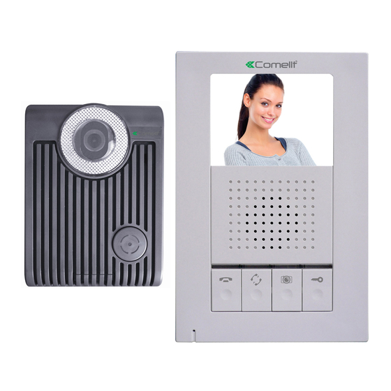
- Page 1 HANDS-FREE EXPANDABLE VIDEO INTERCOM SYSTEM HFX-700M KIT OWNER S MANUAL INSTALLATION AND OPERATION...
-
Page 2: Table Of Contents
2.3.HFX-700M KIT Packaging 3.HFX-700M KIT Installation 3.1. Positioning the devices 3.2. Installation 3.3. Door Release Options 4. HFX-700M KIT Test after installation .1. Basic function test 4.2. Door release test(optional) 5. HFX-700M KIT Operation 5.1.Visitor Calls from Door Camera 5.2.Audio and Video monitoring 5.3. -
Page 3: Important Safety Instructions
IMPORTANT SAFETY INSTRUCTIONS WARING: TO REDUCE THE RISK OF FIRE OR ELECTRIC SHOCK, DO NOT EXPOSE THE MONITOR OR POWER ADAPTER TO WATER OR MOISTURE. Read Instructions -All the safety and operating instructions should be read before operating this equipment. These instructions should be retained for future reference. -
Page 4: Warning
WARNING WARNING: TO REDUCE THE RISK OF FIRE OR ELECTRIC SHOCK, DO NOT EXPOSE THE MONITOR OR POWER ADAPTER TO WATER OR MOISTURE. CAUTION: DO NOT OPEN. RISK OF ELECTRICAL SHOCK. CAUTION! TO REDUCE RISK OF ELECTRICAL SHOCK, DO NOT REMOVE COVER OR BACK, NO USER SERVICEABLE PARTS INSIDE, REFER SERVICING TO QUALIFIED SERVICE PERSONNEL. -
Page 5: Fcc Class B Notice
FCC CLASS B NOTICE NOTE: This equipment has been Certified and found to comply with the limits regulated by FCC,and CE. Therefore, it is designed to provide reasonable protection against interference and will not cause interference with other appliance usage. However, it is imperative that the user follows this manuals guidelines to avoid improper usage which may result in damage to the unit, electrical shock, and fire hazard or injury. -
Page 6: Hfx-700M Kit Video Intercom System
HFX-700M KIT VIDEO INTERCOM SYSTEM 1.Introduction Thank you for purchasing the Hands-Free expandable Video Intercom System HFX-700M. This intercom system uses 2-wire installation, and operation is simple. Allows you to identify and communicate with callers at the door, from the security and convenience of any room in your home or office. -
Page 7: Hfx-700M Kit Parts Identification
2.HFX-700M KIT Parts Identification 2.1. Main Monitor Main monitor 178mm (7.0 ) 36mm 10 11 (1.42 ) 118mm (4.65 ) HFX-700M Main monitor identification: 3.5" Color TFT Screen Speaker In use LED Monitor LED Intercom LED Speaking out LED Microphone... - Page 8 Main monitor wall mount bracket Wall mount bracket Wiring terminals 136mm OUT+ (5.35 ) " OUT- OUT+ OUT- <+> POWER <-> <+> 89mm POWER <-> (3.5 ) " 8.4mm(0.33 ) " Magnetic switch sensor connection: for door status detection External chime or light indicator connection: for optional third party device Expansion monitor connection: for more indoor monitor expansion (w/polarity) Door camera connection(2): to the 2nd door camera terminals(no polarity)
-
Page 9: Door Camera
(-6 degrees, 0 degrees, 8 degrees, 16 degrees) Jumper 2 (enable/disable light senor) Jumper 1 (dry contact or current output selection) Wire to door strike Wire to main Monitor 2.3.HFX-700M KIT Packaging HANDS-FREE EXPANDABLE OUT+ VIDEO INTERCOM SYSTEM OUT- <+>... -
Page 10: Hfx-700M Kit Installation
3. HFX-700M KIT Installation 3.1. Positioning the devices Main monitor Door camera Proper height: View Angle: 70cm 100cm (27.6 ) " (39.3 ) " 165cm 170cm (64.9 ) " (66.9 ) " 50cm(19.7 ) " 50cm(19.7 ) " The proper height of monitor or door camera is 160~170cm(63"~67") from the ground. -
Page 11: Installation
3.2. Installation STAGE 1: Installation main monitor A. Fasten the wall mount bracket using the provided hardware. B. Fasten wires on terminals accordingly. (Refer to STAGE 3) C. Plug pin wires and mount the monitor unit on bracket. PT 1 PT 2 DG 1 DG 2... - Page 12 STAGE 3: Wiring and setting A. Wire the system from terminals to terminals as accordingly. B. Select and plug JP2 to its RIGHT( ) to disable automatic LED light supplement at night. Factory setting is LEFT( ) as enable. C. Select and plug JP1 to its RIGHT( ) for direct current output control.
-
Page 13: Door Release Options
3.3. Door Release Options Each Door Camera on the system is able to operate and release one electric lock. On a full system with 2 door cameras, the user is able to release up to two electric locks. The system can only release one electric lock at a time, depending on which door camera the call originated from. -
Page 14: Hfx-700M Kit Test After Installation
4. HFX-700M KIT Test after installation Installed and with a good line, the need to test the system. 4.1. Basic function test A. Plug in the power supply. B. Press the call button on the door camera. C. Check and adjust doorbell volume. -
Page 15: Hfx-700M Kit Operation
5. HFX-700M KIT Operation Operating the video intercom system consists of responding to visitor calls from door camera, releasing a door strike from indoor monitor; audio and video monitoring from any indoor monitor; voice broadcast from one monitor to all others; engage intercom function after voice broadcast. -
Page 16: Expansion Options
A. HFX-700M package consists a main monitor, a door camera, and a power adaptor for the monitor. B. With HFX-700M KIT as a basic, the system is capable of expanding up to a total of 4 indoor monitors and 2 door cameras. Expansion monitor can choose video(EX-700H) or non-video(EX-700A). -
Page 17: Wiring Diagram
OUT- OUT- OUT- <+> <+> <+> POWER POWER POWER <-> Black <-> Black <-> Black OUT+ OUT- <+> POWER <-> Black Main monitor Wiring terminal The 2nd door camera The 1st door camera HFX-700M Kit EX-700D Wiring terminal Wiring terminal... -
Page 18: Expansion Video Monitor (Ex-700H)
1. Expansion Video Monitor (EX-700H) 1.1. EX-700H Identification EX-700H 178mm (7.0 ) 36mm 10 11 (1.42 ) 118mm (4.65 ) EX-700H identification: 3.5" Color TFT Screen Speaker In use LED Monitor LED Intercom LED Speaking out LED Microphone Cut-off button( ) Intercom button( ) Monitoring button( ) Door release button( ) - Page 19 EX-700H Wall mount bracket Wiring terminals Wall mount bracket 136mm OUT+ OUT+ OUT- (5.35 ) OUT- <+> POWER <-> <+> POWER <-> 89mm (3.5 ) 8.4mm(0.33 ) Magnetic switch sensor connection: for door status detection OUT: to next EX-700H monitor, w/polarity IN: from HFX-700M or EX-700H monitor, w/polarity Power adapter connection EX-700H packaging...
-
Page 20: Ex-700H Installation
1.2. EX-700H Installation STAGE 1: Installation expansion monitor A. Fasten the wall mount bracket using the provided hardware. B. Fasten wires on terminals accordingly. (Refer to STAGE 2) C. Plug pin wires and mount the monitor unit on bracket. PT 1 PT 2 OU T+ OU T-... -
Page 21: Ex-700H Operation
1.3. EX-700H Operation Operates the same as the main monitor unit (Refer to page 13). 1.3.1.Broadcast and intercom function A. When system consists of main monitor and expansion monitor and an outdoor doorbell/camera unit, system can provide intercom function. B. Press intercom button from any monitor, all other monitors will react by making bell sound. -
Page 22: Expansion Non-Video Monitor (Ex-700A)
2. Expansion Non-video Monitor (EX-700A) 2.1. EX-700A Identification 178mm (7.0 ) 36mm (1.42 ) 118mm (4.65 ) EX-700A identification: Speaker In use LED Monitor LED Intercom LED Speaking out LED Microphone Cut-off button( ) Intercom button( ) Monitoring button( ) Door release button( ) Power switch Brightness tuner( ) - Page 23 EX-700A Wall mount bracket Wiring terminals Wall mount bracket 136mm OUT+ OUT+ OUT- (5.35 ) OUT- <+> POWER <-> <+> POWER <-> 89mm (3.5 ) 8.4mm(0.33 ) Magnetic switch sensor connection: for door status detection OUT: to next EX-700A non-video monitor, w/polarity IN: from HFX-700M or EX-700A monitor, w/polarity Power adapter connection EX-700A packaging...
-
Page 24: Ex-700A Installation
2.2. EX-700A Installation STAGE 1: Installation expansion monitor A. Fasten the wall mount bracket using the provided hardware. B. Fasten wires on terminals accordingly. (Refer to STAGE 2) C. Plug pin wires and mount the monitor unit on bracket. PT 1 PT 2 OU T+ OU T-... -
Page 25: Ex-700A Operation
2.3. EX-700HA Operation A. Operates the same as the main monitor unit (Refer to page 13). B. EX-700A only audio function, not video function. 2.3.1.Broadcast and intercom function A. When system consists of main monitor and expansion non-video monitor and an outdoor doorbell/camera unit, system can provide intercom function. -
Page 26: Door Camera (Ex-700D)
3. Door Camera (EX-700D) 3.1. EX-700D Identification 130mm (5.12 ) " 36mm 98mm (1.42 ) " (3.86 ) " EX-700D identification: White LED Illumination 1/3" Color CCD Microphone Speaker Call button Screw cover CCD view angle knob (-6 degrees, 0 degrees, 8 degrees, 16 degrees) Jumper 2 (enable/disable light senor) Jumper 1 (dry contact or current output selection) Wire to door strike... -
Page 27: Ex-700D Installation
3.2. EX-700D Installation STAGE 1: Installation door camera A. Use screws wrench disassemble screw and remove door camera unit from bracket. B. Fasten wall mount bracket on position. C. Fasten wires on terminals and select jumpers for desire function. (refer to STAGE 2) D. -
Page 28: Technical Specifications
TECHNICAL SPECIFICATIONS HFX-700M(main monitor) Display: 3.5 digital TFT-LCD " Resolution: 320 x 240 pixels Auto Timer (visitor call): 30 seconds time out; 90 seconds for conversation Auto Timer (intercom): 20 seconds time out; 90 seconds for conversation Operating Temperature: 14 F ~ 140 F, indoor Dimensions (w/ bracket): 4.65 (L) x 7.0 (W) x 1.42 (D) "... - Page 29 EX-700H(optional expansion monitor) Display: 3.5 digital TFT-LCD " Resolution: 320 x 240 pixels Auto Timer (visitor call): 30 seconds time out; 90 seconds for conversation Auto Timer (intercom): 20 seconds time out; 90 seconds for conversation Operating Temperature: 14 F ~ 140 F, indoor Dimensions (w/ bracket): 4.65 (L) x 7.0 (W) x 1.42 (D) "...
-
Page 30: Trouble Shooting
TROUBLE SHOOTING Before requesting service, check the troubleshooting quide to solve the problem. Problem Solution Make sure AC plug is firmly inserted into the AC outlet. Make sure the power terminal is No power firmly connected into the monitor unit. Check (no picture on monitor) to ensure polarity is correct. -
Page 31: Service And Warranty
SERVICE AND WARRANTY To receive after sales service, please provide the following information when contact. a. Name of the product b. Model and serial number of the product c. The store s name where you purchased d. Date purchased e. Idea and area of possible problems Information Card Product name Model and serial number... - Page 32 Info@comelitusa.com...