
Related Manuals for Comelit HFX-700R KIT


Summary of Contents for Comelit HFX-700R KIT
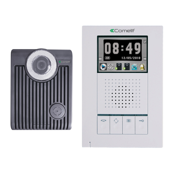
- Page 1 HF COLOR VIDEO INTERCOM WITH RECORDING HFX-700R KIT OWNER S MANUAL INSTALLATION AND OPERATION...
-
Page 2: Table Of Contents
2.3.HFX-700R KIT Packaging 3.HFX-700R KIT Installation 3.1. Positioning the devices 3.2. Installation 3.3. Door Release Options 4. HFX-700R KIT read before operation .1. Attention 4.2. On screen menu icons 4.3. Setup menu 4.3.1. Adjust clock 4.3.2. Door open status indication 4.3.3. -
Page 3: Important Safety Instructions
IMPORTANT SAFETY INSTRUCTIONS WARNING: TO RE DUCE TH E RISK OF FIRE OR E LECTRIC SHOCK , DO NOT E XPOSE THE MONITOR OR POW ER ADAP TER TO WATE R OR MOIST URE . Read Instructions -All the safety and operating instructions should be read before operating this equipment. -
Page 4: Warning
WARNING WARNING: TO REDUCE THE RISK OF FIRE OR ELECTRIC SHOCK, DO NOT EXPOSE THE MONITOR OR POWER ADAPTER TO WATER OR MOISTURE. CAUTION: DO NOT OPEN. RISK OF ELECTRICAL SHOCK. CAUTION! TO REDUCE RISK OF ELECTRICAL SHOCK, DO NOT REMOVE COVER OR BACK, NO USER SERVICEABLE PARTS INSIDE, REFER SERVICING TO QUALIFIED SERVICE PERSONNEL. -
Page 5: Fcc Class B Notice
FCC CLASS B NOTICE NOTE: This equipment has been Certified and found to comply with the limits regulated by FCC,and CE. Therefore, it is designed to provide reasonable protection against interference and will not cause interference with other appliance usage. However, it is imperative that the user follows this manuals guidelines to avoid improper usage which may result in damage to the unit, electrical shock, and fire hazard or injury. -
Page 6: Hfx-700R Kit Video Intercom System
HFX-700R KIT VIDEO INTERCOM SYSTEM 1. HFX-700R KIT introduction Thank you for purchasing this Video Intercom System. This advanced system not only allows you to identify and communicate with visitors at the door and allows for remote door strike release, it can also record the video intercom communication on a micro SD card for later playback. -
Page 7: Hfx-700R Kit Parts Identification
2.HFX-700R KIT Parts Identification 2.1. Main Monitor 178mm (7.0 ) 36mm 10 11 12 13 (1.42 ) 118mm (4.65 ) HFX-700R Main monitor identification: Micro SD card slot socket 3.5" Color TFT Screen Touch sensitive buttons (4 on each side, unmarked) - Page 8 HFX-700R Main menu identification: Confirm Video and menu display area Tab right Tab left Play Setup 1st doorbell camera 2st doorbell camera Paging other monitor Chime enable or disable Main monitor w all mount bracket Wall mount bracket Wiring terminals PT 1 PT 2 136mm...
-
Page 9: Door Camera
(-6 degrees, 0 degrees, 8 degrees, 16 degrees) Jumper 2 (enable/disable light senor) Jumper 1 (dry contact or current output selection) Wire to door strike Wire to main Monitor 2.3.HFX-700R KIT Packaging HF COLOR VIDEO INTERCOM OUT + WITH RECORDING OUT- <+ >... -
Page 10: Hfx-700R Kit Installation
3. HFX-700R KIT Installation 3.1. Positioning the devices Main monitor Door camera Proper height: View Angle: 70cm 100cm (27.6 ) " (39.3 ) " 165cm 170cm (64.9 ) " (66.9 ) " 50cm(19.7 ) " 50cm(19.7 ) " The proper height of monitor or door camera is 160~170cm(63"~67") from the ground. -
Page 11: Installation
3.2. Installation STAGE 1: Installation of main monitor A. Fasten the wall mount bracket using the provided hardware. B. Fasten wires on terminals accordingly. (Refer to STAGE 3) C. Plug pin wires and mount the monitor unit on bracket. Do not plug pow er at this stage. - Page 12 STAGE 3: Wiring and settings A. Wire the system from door camera terminals to monitor terminals accordingly. B. Select and plug JP2 to its RIGHT( ) to disable LED illumination of the doorbell camera when it's activated. Factory setting is LEFT( ) which enables automatic LED illumination.
-
Page 13: Door Release Options
3.3. Door Release Options Each Door Camera on the system is able to operate and release one electric lock. On a full system with 2 door cameras, the user is able to release up to two electric locks. The system can only release one electric lock at a time, depending on which door camera the call originated from. -
Page 14: Hfx-700R Kit Read Before Operation
4. HFX-700R KIT read before operation 4.1. Attention A. Micro SD card, SDHC(High Capacity SD card), is not included in this product package. B. Insert SD card properly. The SD card can be 2GB to 16GB memory size. SD card socket C. -
Page 15: Setup Menu
4.3. Setup menu A. Move cursor to SETUP icon at main menu; B. Press can enter setup menu. 4.3.1. Adjust clock A. At setup menu, can move the cursor; can alter parameter (figure 1); can save your new setup. 4.3.2. Door open status indication A. -
Page 16: Video Or Photo Recording
4.3.3 Video or photo recording A. At setup menu, can move the cursor to the mode you like; can save your setup. B. If select , enable automatic video recording mode, 20 seconds a section, when visitor calls from doorbell camera. C. -
Page 17: Intercom Function Operations
4.4. Intercom function operations 4.4.1. Push to talk function A. Speach open LED on means voice is free to go out from monitor to door camera. B. During conversation, press Monitor Button for 2 seconds to switch to push to talk mode. Under this mode, press-on Monitor Button speaking out LED on allows push to talk to go out to door camera;... -
Page 18: Zoom And P An/Tilt Function
4.4.3. zoom and p an/tilt function A. While talking to the doorbell camera from main monitor, tenant can at the same time operate the on-screen-menu to stop or resume video recording. B. To operate zoom and pan/tilt function has to stop recording first and resume afterward. -
Page 19: All Page Announcement And Intercom Among Monitors
4.4.5. All page announcement and intercom among monitors A. From any monitor, tenant can press intercom button or select the function from the on-screen main monitor menu to page and make nnoucements to other monitors (figure 2). B. Paging and a nnoucements can last for 30 seconds time, if any other monitor press the intercom button to... -
Page 20: Delete Video/Photo Section(S)
10062800 /100401-1 1 01224 00 10/06/28 04 57 39 (figure 1) (figure 2) 2010/06/28 04 5 7 3 9 1 0 1 2 0 8 0 0 1 0 / 1 2/ 0 8 /1 1 2 6 5 5 - 1 0 4 5 7 3 9 (figure 3) (figure 4) -
Page 21: Expansion Options
AWG#18 100m Signal wires (328 feet) (328 feet) parallel wires NOTE : CAT-5 can NOT serve the purpose on this kind of installation condition. B Max B Max B Max A Max A Max EX-700D HFX-700R KIT EX-700H or EX-700A... - Page 22 System layout 2: NOTE 1: The wiring HUB can amplify and distribute the 2-wire signal among the main monitor and sub-monitors. NOTE 2: the system is capable of expanding up to a total of 5 monitors with 1 EX-HUB or 8 total monitors with 2 EX-HUBs connected in one system. Maximum wiring distance (using dry contact lock control at doorbell camera) Wire assignment...
- Page 23 A Max A Max HFX-700R EX-700D EX-700H or EX-700A B Max C Max EX-HUB OUT1 OUT2 OUT3 POWER OUT4 POWER LED EX-700H or EX-700A NOT E 1:OUT4 can also be used to connect to a expansion monitor. NOT E 2:wiring distance<300ft.
-
Page 24: Expansion Video Monitor (Ex-700H)
1. Expansion Video Monitor (EX-700H) 1.1. EX-700H Identification EX-700H 178mm (7.0 ) 36mm 10 11 (1.42 ) 118mm (4.65 ) EX-700H identification: 3.5" Color TFT Screen Speaker In use LED Monitor LED Intercom LED Speach open LED Microphone Cut-off button( ) Intercom button( ) Monitoring button( ) Door release button( ) - Page 25 EX-700H Wall mount bracket Wiring terminals Wall mount bracket 136mm OUT+ OUT+ OUT- (5.35 ) OUT- <+> POWER <-> <+> POWER <-> 89mm (3.5 ) 8.4mm(0.33 ) Magnetic switch sensor connection: for door status detection OUT: to next EX-700H monitor, w/polarity IN: from HFX-700R or EX-700H monitor, w/polarity Power adapter connection EX-700H packaging...
-
Page 26: Ex-700H Installation
1.2. EX-700H Installation STAGE 1: Installation of the expansion monitor A. Fasten the wall mount bracket using the provided hardware. B. Fasten wires on terminals accordingly. (Refer to STAGE 2) C. Plug pin wires and mount the monitor unit on bracket. Do not plug pow er at this stage. -
Page 27: Ex-700H Operation
1.3. EX-700H Operation 1.3.1. Visitor Calls from Door Camera A. When the Call button on the camera is pressed, All monitors on the system will ring with a chime sound and all monitors will be activated. B. After the call, if nothing on the monitor is pressed, the system will time out after 30 seconds. -
Page 28: Expansion Audio Monitor (Ex-700A)
2. Expansion audio Monitor (EX-700A) 2.1. EX-700A Identification 178mm (7.0 ) 36mm (1.42 ) 118mm (4.65 ) EX-700A identification: Speaker In use LED Monitor LED Intercom LED peach open Microphone Cut-off button( ) Intercom button( ) Monitoring button( ) Door release button( ) Power switch Bell Volume tuner( ) Speaker Volume tuner( ) - Page 29 EX-700A Wall mount bracket Wiring terminals Wall mount bracket 136mm OUT+ OUT+ OUT- (5.35 ) OUT- <+> POWER <-> <+> POWER <-> 89mm (3.5 ) 8.4mm(0.33 ) Magnetic switch sensor connection: for door status detection OUT: to next EX-700A audio monitor, w/polarity IN: from HFX-700R or EX-700A monitor, w/polarity Power adapter connection EX-700A packaging...
-
Page 30: Ex-700A Installation
2.2. EX-700A Installation STAGE 1: Installation of the expansion monitor A. Fasten the wall mount bracket using the provided hardware. B. Fasten wires on terminals accordingly. (Refer to STAGE 2) C. Plug pin wires and mount the monitor unit on bracket. Do not plug pow er at this stage. -
Page 31: Ex-700A Operation
2.3. EX-700A Operation A. Operates the same as EX-700H (Refer to page 25). B. EX-700A audio only function, no video function. 2.3.1. All-page and intercom function A. When system consists of main monitor and expansion audio monitor and an outdoor doorbell/camera unit, the system can provide intercom function. -
Page 32: Door Camera (Ex-700D)
3. Door Camera (EX-700D) 3.1. EX-700D Identification 130mm (5.12 ) " 36mm 98mm (1.42 ) " (3.86 ) " EX-700D identification: White LED Illumination 1/3" Color CCD Microphone Speaker Call button Screw cover CCD view angle knob (-6 degrees, 0 degrees, 8 degrees, 16 degrees) Jumper 2 (enable/disable light senor) Jumper 1 (dry contact or current output selection) Wire to door strike... -
Page 33: Ex-700D Installation
3.2. EX-700D Installation STAGE 1: Installation of the door camera A. Use security screw wrench disassemble screw and remove door camera unit from bracket. B. Fasten wall mount bracket on position. C. Fasten wires on terminals and select jumpers for desired function. (refer to STAGE 2) D. -
Page 34: Metal Door Camera Housing (Ex-700V)
Metal Door Camera Housing (EX-700V) 4.1. EX-700V contents EX-700V is an optional housing assembly kit to enclose EX-700D to become flush mount metal doorbell camera. Bracket 1 Front panel Rubber seal 4.5 x10mm Screw 3.0 x6mm Screw Bracket 2 Embed box Screw wrench Depends on different wall materials, please refer to the cut open size for EX-700V. -
Page 35: Assembly Procedure
4.3. Assembly Procedure STEP 1-1 : A. If on wooden wall, cut open space is 100x150x41mm. B. Embed box may not necessary. Go to Step 2. STEP 1-2 : A. If on cement or brick wall, cut open a hole size of 114x165x49mm. B. -
Page 36: Technical Specifications
TECHNICAL SPECIFICATIONS HFX-700R(main monitor) Display: 3.5 digital TFT-LCD " Resolution: 320 x 240 pixels Auto Timer (visitor call): 30 seconds time out; 90 seconds for conversation Auto Timer (intercom): 30 seconds time out; 90 seconds for conversation Operating Temperature: 14 ~ 140 , indoor Dimensions (w/ bracket): 4.65 (L) x 7.0 (W) x 1.42 (D) "... - Page 37 EX-700H(optional expansion monitor) Display: 3.5 digital TFT-LCD " Resolution: 320 x 240 pixels Auto Timer (visitor call): 30 seconds time out; 90 seconds for conversation Auto Timer (intercom): 30 seconds time out; 90 seconds for conversation Operating Temperature: 14 ~ 140 , indoor Dimensions (w/ bracket): 4.65 (L) x 7.0 (W) x 1.42 (D) "...
-
Page 38: Trouble Shooting
TROUBLE SHOOTING Before requesting service, check the troubleshooting quide to solve the problem. Problem Solution Make sure AC plug is firmly inserted into the AC outlet. Make sure the power terminal is No power firmly connected into the monitor unit. Check (no picture on monitor) to ensure polarity is correct. -
Page 39: Service And Warranty
SERVICE AND WARRANTY To receive after sales service, please provide the follow ing information when contact. a. Name of the product b. Model and serial number of the product c. The store s name where you purchased d. Date purchased e. - Page 40 http:// w w w .comelitusa.com Info@comelitusa.com...