Table of Contents
Advertisement
Available languages
Available languages
Quick Links
Advertisement
Chapters
Table of Contents

Related Manuals for Comelit HFX-9000M


Summary of Contents for Comelit HFX-9000M
- Page 1 TECHNICAL MANUEL MANUAL MANUAL TECHNIQUE TÉCNICO PUSH HERE Complete technical manual for HFX-9000M Single-User Kit Manuel technique complet HFX-9000M pour le Kit Utilisateur Individuel Manual técnico integral HFX-9000M del Kit de Usuario Único...
-
Page 2: Table Of Contents
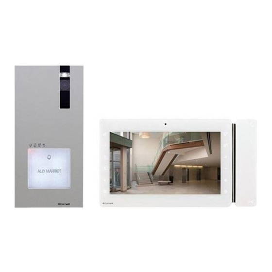
4.9.2.4 COMPATIBILITY TABLE ..............36 3.1 OPERATING DISTANCES AND SYSTEM LAYOUT ..........9 5. System function................. 37 3.1.1 Single-User Kit art. HFX-9000M..............9 3.1.2 Maximum Expansion Monitors in Daisy Chain connection .......10 5.1 PERFORMING CALLS ....................37 3.1.3 Full System Expansion Diagram ..............10 5.1.1 How to call from the external unit ...............37... - Page 3 Thank you for purchasing the hands free kits art. HFX-9000M! This intercom system uses 2-wire installation and allows you to identify and communicate with callers at the door, from the security and convenience of any room in your home or office. Visitors activate the system by pressing a call pad on the external unit, which sounds a doorbell chime as well as turning on the inside "hands free video monitor".
-
Page 4: Contents Of The Package
+ terminal block support screws Technical manual QUICK ×4 REFERENCE GUIDE ×2 ×2 ×4 PUSH HERE clips for dry screws Quick reference Guide for Single-User Kit HFX-9000M lined walls tech sheet also available in French and Spanish... -
Page 5: Parts Identification
2. Parts identification 3.79 in 1.06 in 2.1 EX-DSME EXTERNAL UNIT PUSH HERE 1. Die-cast aluminium cover 10. CNF programming confirmation switch 2. Camera lighting LED 11. Loudspeaker volume control Can be disabled by setting DIP 7 to ON, see page 31 "4.6.2 12. -
Page 6: Ex-9000H Monitor
2.2 EX-9000H MONITOR 8.77 in 0.98 in 1. 7” colour LCD screen 2. Microphone 3. S1 Micro-switches for user code setting 4. Terminal block for system connection: L L Bus line connection terminals - + Power supply terminals IN2 IN1 Input terminals (programmable) S- S+ Terminals for additional ringtone output CFP2 CFP1 Outside door call input 5. -
Page 7: Capacitive-Touch Key Description
2.2.1 Capacitive-touch key description SPEAKER AND AUDIO ACTIVATION KEY / PAGING CALL KEY / HANDS-FREE MODE ACTIVATION KEY Answer call Can be used to activate a conversation with the external unit or to end a conversation. Paging call Internal paging function: can be used to make a paging call to the internal units with the same user code. General paging to another user code: can be used to make a paging call to the internal units with another user code. -
Page 8: 1209/8 Bus Power Supply
2.3 1209/8 BUS POWER SUPPLY 2.6 in 5.51 in 1. L1 | L1 monitor connection 1 L2 | L2 monitor connection 2 L3 | L3 monitor connection 3 L4 | L4 monitor connection 4 L5 | L5 monitor connection 5 L6 | L6 monitor connection 6 L7 | L7 monitor connection 7 L8 | L8 monitor connection 8... -
Page 9: System Installation
After the procedure the LEDs will turn off. The EX-DSQE is the Additional External Unit for Single-User Kits and contains the external unit EX-DSME and the Video Door Expander 1405 EX-DSQE EX-DSME 1405 3.1.1 Single-User Kit art. HFX-9000M EX-9000H 1209/8 EX-DSME... -
Page 10: Maximum Expansion Monitors In Daisy Chain Connection
EX-9000H EX-9000H EX-9000H EX-9000H expansion monitor expansion monitor expansion monitor Maximum 2 monitors per output 1209/8 EX-DSME HFX-9000M 3.1.3 Full System Expansion Diagram EX-9000H EX-9000H EX-9000H EX-9000H EX-9000H EX-9000H EX-9000H EX-9000H expansion monitor expansion monitor expansion monitor... -
Page 11: Basic Single-User Kit
Basic single-user kit STANDARD INSTALLATION EX-9000H LEAVE DEFAULT SETTING 34 Vdc 1209/8 LP LP L1 L1 L2 L2 L3 L3 L4 L4 L5 L5 L6 L6 L7 L7 L8 L8 110-240V EX-DSME Wiring diagram: MXK/039QCU Local lock release button... -
Page 12: Expanded Single-User Kit
Expanded single-user kit MAXIMUM EXPANSION IN DAISY CHAIN CONNECTION EX-9000H EX-9000H LEAVE DEFAULT SETTING LEAVE DEFAULT SETTING EX-9000H EX-9000H LEAVE DEFAULT SETTING LEAVE DEFAULT SETTING REMOVE CV5 REMOVE CV5 EX-9000H EX-9000H LEAVE DEFAULT SETTING LEAVE DEFAULT SETTING EX-9000H EX-9000H LEAVE DEFAULT SETTING LEAVE DEFAULT SETTING REMOVE CV5 REMOVE CV5... -
Page 13: Expanded Single-User Kit
Expanded single-user kit MAXIMUM EXPANSION Wiring diagram: MXK/012BQCU... -
Page 14: Multi-Users Expansion
Multi-users expansion TWO-USERS EXPANSION EX-9000H EX-9000H LEAVE DEFAULT SETTING SET THE ADDRESS 1209/8 LP LP L1 L1 L2 L2 L3 L3 L4 L4 L5 L5 L6 L6 L7 L7 L8 L8 110-240V REMOVE WHEN LINE IS USED EX-DSME Local lock release button. For programming, see page 32 "4.6.3 Enabling the buttons for 2/4 users"... -
Page 15: Multi-Users Expansion
Multi-users expansion FOUR-USERS EXPANSION Wiring diagram: MXK/012AQCU... -
Page 16: Full Multi-Users Expansion
Full multi-users expansion FOUR-USERS EXPANSION WITH FOUR EXTERNAL UNIT Wiring diagram: MXK/012CQCU... -
Page 17: Basic Single-User Kit
Basic single-user kit TV INTERFACE (Art. 1257) CONNECTION EX-9000H LEAVE DEFAULT SETTING IND 1 SINGLE ADDRESS MODE REMOVE CV5 1234 67 1257 1200UL IND 2 12V~ 120V~ CABLE EQUIPMENT CP2N 1209/8 LP LP L1 L1 L2 L2 L3 L3 L4 L4 L5 L5 L6 L6 L7 L7 L8 L8 110-240V EX-DSME Local lock release button. -
Page 18: Additional Relay Module (Art. 1256) Connection
Basic single-user kit ADDITIONAL RELAY MODULE (Art. 1256) CONNECTION EX-9000H LEAVE DEFAULT SETTING 1256 1200UL 12V~ 120V~ 12/24V 1214/2C AC/DC 1209/8 LP LP L1 L1 L2 L2 L3 L3 L4 L4 L5 L5 L6 L6 L7 L7 L8 L8 110-240V EX-DSME Local lock release button For further information, see page... -
Page 19: Cctv Camera Interface (Art. 1409) Connection
Basic single-user kit CCTV CAMERA INTERFACE (Art. 1409) CONNECTION EX-9000H LEAVE DEFAULT SETTING 1209/8 LP LP L1 L1 L2 L2 L3 L3 L4 L4 L5 L5 L6 L6 L7 L7 L8 L8 110-240V 1409 1200UL 12V~ 120V~ IN IN 1234 67 EX-DSME Local lock release button For further information, see page 35... -
Page 20: Full Multi-Users Expansion Four-Users Expansion With Four External Unit And Cctv Camera Interface (Art. 1409)
Full multi-users expansion FOUR-USERS EXPANSION WITH FOUR EXTERNAL UNIT and CCTV CAMERA INTERFACE (Art. 1409) Wiring diagram: MXK/015BQCU... -
Page 21: Assembly Art. Ex-9000H Internal Unit
3.2 ASSEMBLY ART. EX-9000H INTERNAL UNIT 3.2.1 Surface-mounting (accessory for EX-9000H included) 8.77 in min = 2.6 in max = 2.8 in CLICK ! TO OPEN... -
Page 22: Dry-Wall Mounting (Accessory For Ex-9000H Included)
3.2.2 Dry-wall mounting (accessory for EX-9000H included) 8.77 in 8 . 0 CLICK ! TO OPEN... -
Page 23: Installation Of External Unit Art. Ex-Dsme
3.3 INSTALLATION OF EXTERNAL UNIT ART. EX-DSME TO OPEN The camera must not be installed in front of light sources, or in places where the filmed subject is against the light. In dim environments, we recommend additional lighting is provided. 19.68 in CAUTION! 72°... -
Page 24: How To Change The Nameplate Of The External Unit Art. Ex-Dsme
You can download the free software (art. 1235A) from the website pro.comelitgroup.com to print the entrance panel name tags, using the adhesive pre-cut sheets available in our catalogue (art. 1217A) CLACK! CLACK! Before fixing the screw, make sure that you do not need to program the external unit (See page 31 "4.6 Configuration EX-DSME"... -
Page 25: Surface-Mounting Of The Power Supply Art. 1209/8
3.4 SURFACE-MOUNTING OF THE POWER SUPPLY ART. 1209/8... -
Page 26: Additional Features Programming
4. Additional features programming 4.1 ADDRESSING ART. EX-9000H BY MEANS OF DIP SWITCH „ Set the user codes on S1 DIP-Switches as indicated in the table on page 32 "TAB. A" . 4.2 CONFIGURATION CAPACITIVE-TOUCH KEYS ART. EX-9000H „ Set the S2 DIP switches combination corresponding to the functions that you want to programme for ALL KEYS as shown in the table below. -
Page 27: Quick Programming
4.2.2 Quick programming For the quick programming of the following functions: • generic actuator (ACT), • internal intercom calls (INT), • internal paging calls (PAG), • Self ignition main external unit (AI), • Doctor mode (D) Example: „ Set the S2 DIP switches combination corresponding to Choose S2 DIP switches combination the functions that you want to... -
Page 28: How To Program The Intercom Function
4.2.3.2 HOW TO PROGRAM THE INTERCOM FUNCTION Example: key = general intercom to user code 3 √ Take note of the S1 setting and restore it when programming is complete Enter programming mode „ Set S2 DIP switch 5-6 to the combination 01 »... -
Page 29: How To Program The Self Ignition Function
4.2.3.4 HOW TO PROGRAM THE SELF IGNITION FUNCTION Example: √ Take note of the S1 setting and restore it when programming is complete Enter programming mode „ Set S2 DIP switch 5-6 to the combination 01 » the Privacy LED flashes 2.1 Choose the function: refer to the "4.2.1 Preset function"... -
Page 30: Programming Reset
4.3 PROGRAMMING RESET Factory settings: DIP OFF • Button functions for the S2 DIP switch 1-2-3-4 combination; • Intercom address absent; • Range function and min./max. addresses absent; • Ringtone reset. • Input IN 1 - IN 2 > LED (default). •... -
Page 31: Changing Monitor Ringtones
4.5 CHANGING MONITOR RINGTONES 1. Keep the button pressed until a confirmation tone is emitted (this operation is only possible with the system in stand- by; otherwise the signalling LED will flash to warn the user) 2. Press and release the button: once (1 confirmation tone is emitted) to change the ringtone of calls from the external unit. -
Page 32: Call Address Programming For 2/4 Users
4.6.3 Enabling the buttons for 2/4 users √ Take note of the DIP-switch settings On the S1 DIP-switch, set the code corresponding to the function you want to program. button 1 buttons 1-2 buttons 1-2- Restore enabled with enabled 3-4 enabled default call address with call... -
Page 33: Actuator Relay Module Art. 1256
4.7.1 Parts description 1. JP4 2. JP3 3. JP2 To use the actuator relay module with kit HFX-9000M „ Move jumper JP2 to position 2 „ Move jumper JP3 to position 2 „ Move jumper JP4 to position 2 4. S1 DIP switch for different setting 5. -
Page 34: Parts Description
3. IND 1 DIP switch for settings 4. IND 2 DIP switch for settings 5. JP3 jumper for settings To use the Art. 1257 with kit HFX-9000M: move jumper JP3 to position S2 6. Terminal block for system connection: ~+, ~- power supply input terminals L L BUS line input OUT GND 12V open collector output (max 30mA). -
Page 35: Cctv Camera Interface Art. 1409
4.9 CCTV CAMERA INTERFACE ART. 1409 Art. 1409 allows to manage analog CCTV camera (up to 3). 1409 4.9.1 Parts description 1. Terminal block M2 for system connection: INA not used GND Common contact V1 S1 Coax input camera 1 V2 S2 Coax input camera 2 V3 S3 Coax input camera 3 2. -
Page 36: Function 2: Actuator With Code Mode
4.9.2.3 FUNCTION 2: ACTUATOR WITH CODE MODE √ NOTE: Before programming the module, see "4.9.2.4 Compatibility Table" . By pressing the button programmed as "coded actuator", it is possible to toggle between the different cameras. Microswitch “S1” must be set as shown in following table: CORRESPONDENCE OF 1409 ADDRESS ACTUATOR WITH CODE ON BRACKET DIP 1 DIP 2... -
Page 37: System Function
5. System function 5.1 PERFORMING CALLS 5.1.1 How to call from the external unit 5.1.2 How to answer a call from an internal unit » On receipt of a call from the external unit you will hear the „ To send the call from an external unit, touch the button call ringtone corresponding to the user you want to contact. -
Page 38: Soft-Touch Key Activation
5.3 SOFT-TOUCH KEY ACTIVATION „ Touch to activate the function keys 5.4 INTERCOM FUNCTION 5.4.1 How to transmit a call to the other internal 5.4.2 How to answer a call from an internal unit units » On receipt of a call from the internal unit you will hear the This function can be used to transmit a call to the other internal call ringtone. -
Page 39: How To Display On The Monitor The Image Transmitted From The Cctv Camera
5.5.1 How to display on the monitor the image transmitted from the CCTV camera √ During “call in progress” or during Self-ignition. „ Press again to cycle through several cameras and come „ Press the programmed button to display on the monitor the back to the external unit image transmitted from the CCTV camera. -
Page 40: Adjustments
5.10 ADJUSTMENTS 5.10.1 Audio volume control „ Press to enable the adjustment of the audio volume. » The LED comes on. „ Adjust by pressing the + / - keys. Tone changes and Privacy LED flashes when the parameter reaches minimum or maximum value. -
Page 41: Technical Specification
6. Technical specification 6.1 EX-9000H MAIN MONTOR Display 4.3’’ Color LCD Screen Resolution 480x272pixel Auto Timer (intercom) 300sec Operating Temperature Class B1 normal range indoor 41° F /104° F (5°C / 40°C) Dimensions (with bracket) 5.59x5.78x0.96 in (142x147x24.5mm) W×H×D Power consumption 15 W MAX 6.2 EX-DSME EXTERNAL UNIT Image Sensor ¼”... -
Page 42: Appendix
7. Appendix 7.1 WARNING WARNING: TO REDUCE THE RISK OF FIRE OR ELECTRIC SHOCK, DO NOT EXPOSE THE MONITOR OR POWER ADAPTER TO WATER OR MOISTURE. CAUTION: DO NOT OPEN. RISK OF ELECTRICAL SHOCK. CAUTION! TO REDUCE RISK OF ELECTRICAL SHOCK, DO NOT REMOVE COVER OR BACK, NO USER SERVICEABLE PARTS INSIDE, REFER SERVICING TO QUALIFIED SERVICE PERSONNEL. -
Page 43: General Product Warranty
7.4 GENERAL PRODUCT WARRANTY: For all Comelit Branded Products (excluding HFX 700, 720 and 900 products) 2 year manufacturer’s warranty from dealer date of Purchase. Proof of purchase by the dealer in the form of an invoice is necessary for all returns. - Page 44 3.1 DISTANCES OPÉRATOIRES ET DISPOSITION DE LA LIGNE ......... 51 4.9.2.1 PROGRAMMATION DU NOMBRE DE CAMÉRAS CONNECTÉES 77 3.1.1 Kit utilisateur individuel art. HFX-9000M ............51 4.9.2.2 FONCTION 1 : MODE ACTIONNEUR GÉNÉRIQUE .......77 3.1.2 Moniteurs évolutifs maximum pour le raccordement en chaîne bouclée..... 52 4.9.2.3 FONCTION 2 : MODE ACTIONNEUR AVEC CODE .......78...
- Page 45 Merci d'avoir acheté le kit mains libres art. HFX-9000M ! Ce système intercom utilise un installation à 2 câbles et vous permet d'identifier et communiquer avec les personnes qui appellent à la porte. Cela vous assure sécurité et commodité depuis toutes les pièces de votre domicile ou de votre bureau.
-
Page 46: Contenu Du Colis
×1 support du ×4 cadre métallique moniteur + bornier Manuel Technique QUICK ×4 REFERENCE GUIDE ×2 ×2 ×4 clips pour les parois à Quick reference Guide for Single-User Kit HFX-9000M revêtement sec notice technique also available in French and Spanish... -
Page 47: Identification Des Pièces
2. Identification des pièces 2.1 POSTE EXTÉRIEUR EX-DSME 3.79 in 1.06 in PUSH HERE 1. Couvercle en aluminium moulé sous pression 9. PR switch entrée/sortie de la programmation 2. Voyant LED caméra 10. CNF switch de confirmation de la programmation 3. -
Page 48: Moniteur Ex-9000H
2.2 MONITEUR EX-9000H 8.77 in 0.98 in 1. Écran LCD couleurs 7 pouces 2. Micro 3. S1 DIP switches pour la programmation du code d’appel 4. Bornes de raccordement de l’installation : L L Bornes de connexion ligne Bus - + Bornes pour alimentation IN2 IN1 Bornes entrée (programmable) S- S+ Bornes pour sonnerie supplémentaire CFP2 CFP1 Entrée de l'appel extérieur... -
Page 49: Description Des Touches Tactiles
2.2.1 Description des touches tactiles TOUCHE PHONIE / D’APPEL DE RADIOMESSAGERIE / D’ACTIVATION DE LA MODALITÉ «MAINS LIBRES» Réponse à un appel Elle peut être utilisée pour activer une conversation entre le poste extérieur ou pour terminer une conversation. Appel de radiomessagerie Elle peut être utilisée pour effectuer un appel de radiomessagerie vers les postes intérieurs avec le même code d’accès. -
Page 50: Alimentation Électrique 1209/8 Bus
2.3 ALIMENTATION ÉLECTRIQUE 1209/8 BUS 2.6 in 5.51 in 1. L1 | L1 raccordement moniteur 1 L2 | L2 raccordement moniteur 2 L3 | L3 raccordement moniteur 3 L4 | L4 raccordement moniteur 4 L5 | L5 raccordement moniteur 5 L6 | L6 raccordement moniteur 6 L7 | L7 raccordement moniteur 7 L8 | L8 raccordement moniteur 8... -
Page 51: Installation Du Système
Lorsque la colonne montante est raccordée pour la première fois, les postes intérieurs acquièrent automatiquement leur sous-adresse. Les LED clignotent simultanément pendant quelques secondes. Au terme de la procédure, les LED s'éteignent. 3.1.1 Kit utilisateur individuel art. HFX-9000M L'art. EX-DSQE est le poste extérieur supplémentaire pour les kits utilisateur individuel. -
Page 52: Moniteurs Évolutifs Maximum Pour Le Raccordement En Chaîne Bouclée
EX-9000H EX-9000H EX-9000H EX-9000H expansion monitor expansion monitor expansion monitor 2 moniteurs maximum par sortie 1209/8 EX-DSME HFX-9000M 3.1.3 Schéma de l’évolution complète du système EX-9000H EX-9000H EX-9000H EX-9000H EX-9000H EX-9000H EX-9000H EX-9000H moniteur évolutif moniteur évolutif moniteur évolutif... -
Page 53: Kit De Base Utilisateur Individuel
Kit de base utilisateur individuel INSTALLATION STANDARD EX-9000H GARDER LE RÉGLAGE PAR DÉFAUT 34 Vdc 1209/8 LP LP L1 L1 L2 L2 L3 L3 L4 L4 L5 L5 L6 L6 L7 L7 L8 L8 110-240V EX-DSME Schéma de connexion : MXK/039QCU Bouton ouvre-porte local... -
Page 54: Kit Utilisateur Individuel Évolutif Évolution Maximum En Raccordement En Chaîne Bouclée
Kit utilisateur individuel évolutif ÉVOLUTION MAXIMUM EN RACCORDEMENT EN CHAÎNE BOUCLÉE EX-9000H EX-9000H GARDER LE RÉGLAGE GARDER LE RÉGLAGE PAR DÉFAUT PAR DÉFAUT EX-9000H EX-9000H GARDER LE RÉGLAGE GARDER LE RÉGLAGE PAR DÉFAUT PAR DÉFAUT SUPPRIMER CV5 SUPPRIMER CV5 EX-9000H EX-9000H GARDER LE RÉGLAGE GARDER LE RÉGLAGE... -
Page 55: Kit Utilisateur Individuel Évolutif Évolution Maximum
Kit utilisateur individuel évolutif ÉVOLUTION MAXIMUM Schéma de connexion : MXK/012BQCU... -
Page 56: Extension Multi-Utilisateurs
Extension multi-utilisateurs EXTENSION DEUX UTILISATEURS EX-9000H EX-9000H GARDER LE RÉGLAGE DÉFINIR L'ADRESSE PAR DÉFAUT 1209/8 LP LP L1 L1 L2 L2 L3 L3 L4 L4 L5 L5 L6 L6 L7 L7 L8 L8 110-240V SUPPRIMER LORSQUE LA LIGNE EST UTILISÉE EX-DSME Bouton ouvre-porte local Pour la programmation, consulter la page... -
Page 57: Extension Multi-Utilisateurs
Extension multi-utilisateurs EXTENSION QUATRE UTILISATEURS Schéma de connexion : MXK/012AQCU... -
Page 58: Extension Multi-Utilisateurs Complète
Extension multi-utilisateurs complète EXTENSION QUATRE UTILISATEURS AVEC QUATRE POSTES EXTÉRIEURS Schéma de connexion : MXK/012CQCU... -
Page 59: Kit De Base Utilisateur Individuel
Kit de base utilisateur individuel BRANCHEMENT DE L'INTERFACE TV (art. 1257) EX-9000H GARDER LE RÉGLAGE PAR DÉFAUT IND 1 MODALITÉ À ADRESSE UNIQUE SUPPRIMER CV5 1234 67 1257 1200UL IND 2 12V~ 120V~ ÉQUIPEMENT CÂBLE CP2N 1209/8 LP LP L1 L1 L2 L2 L3 L3 L4 L4 L5 L5 L6 L6 L7 L7 L8 L8 110-240V EX-DSME... -
Page 60: Module De Relais Supplémentaire (Art. 1256)
Kit de base utilisateur individuel MODULE DE RELAIS SUPPLÉMENTAIRE (art. 1256) EX-9000H GARDER LE RÉGLAGE PAR DÉFAUT 1256 1200UL 12V~ 120V~ 12/24V 1214/2C AC/DC 1209/8 LP LP L1 L1 L2 L2 L3 L3 L4 L4 L5 L5 L6 L6 L7 L7 L8 L8 110-240V EX-DSME Bouton ouvre-porte local. -
Page 61: Branchement De L'interface Caméra Cctv (Art. 1409)
Kit de base utilisateur individuel BRANCHEMENT DE L'INTERFACE CAMÉRA CCTV (art. 1409) EX-9000H GARDER LE RÉGLAGE PAR DÉFAUT 1209/8 LP LP L1 L1 L2 L2 L3 L3 L4 L4 L5 L5 L6 L6 L7 L7 L8 L8 110-240V 1409 1200UL 12V~ 120V~ IN IN... -
Page 62: Branchement De L'interface Caméra Cctv (Art. 1409)
Kit de base utilisateur individuel BRANCHEMENT DE L'INTERFACE CAMÉRA CCTV (art. 1409) Schéma de connexion : MXK/015BQCU... -
Page 63: Ensemble Art. Ex-9000H Poste Intérieur
3.2 ENSEMBLE ART. EX-9000H POSTE INTÉRIEUR 3.2.1 Montage de surface (accessoire pour EX-9000H inclus) 8.77 in min = 2.6 in max = 2.8 in CLICK ! POUR OUVRIR... -
Page 64: Montage Sur Mur Sec (Accessoire Pour Ex-9000H Inclus)
3.2.2 Montage sur mur sec (accessoire pour EX-9000H inclus) 8.77 in 8 . 0 CLICK ! POUR OUVRIR... -
Page 65: Installation Du Poste Extérieur Art. Ex-Dsme
3.3 INSTALLATION DU POSTE EXTÉRIEUR ART. EX-DSME OUVRIR La caméra ne doit pas être installée en face de fortes sources de lumière ni dans des lieux où la personne filmée est fortement à contre-jour. Dans des environnements à faible luminosité, un éclairage supplémentaire est recommandé. 19.68 in 72°... -
Page 66: Remplacement De Le Bouton D'appel
Vous pouvez télécharger le logiciel gratuit (art. 1235A) sur le site Internet pro.comelitgroup.com afin d'imprimer les étiquettes porte- noms de la platine de rue sur les feuilles autocollantes pré-découpées proposées dans notre catalogue (art. 1217A). CLACK! CLACK! BIEN FIXER ! Avant de fixer la vis, veiller à ce qu'il ne soit pas nécessaire de programmer le poste extérieur (Page 72 «4.6 Configuration de EX- DSME»... -
Page 67: Montage De Surface De L'alimentation Art. 1209/8
3.4 MONTAGE DE SURFACE DE L’ALIMENTATION ART. 1209/8... -
Page 68: Programmation Des Fonctions Supplémentaires
4. Programmation des fonctions supplémentaires 4.1 ADRESSAGE DE L'ART. EX-9000H À L'AIDE DU DIP SWITCH „ Régler les codes d'accès sur les DIP switches S1, comme indiqué dans le tableau à la page 76 "TAB. A - Code usager" 4.2 CONFIGURATION DES TOUCHES CAPACITIVES ART. EX-9000H 4.2.1 Fonction de présélection Fonction de présélection DIP 1 DIP 2 DIP 3 DIP 4... -
Page 69: Programmation Rapide
4.2.2 Programmation rapide Pour la programmation rapide des fonctions suivantes : • actionneur générique (ACT), • appels intercommunicants internes (INT), • appels de radiomessagerie internes (PAG), • poste extérieur principal auto-allumage (AI), • fonction Médecin (D) „ Régler les combinaison S2 des Par exemple : DIP switches correspondant aux Choisir la combinaison DIP switches S2... -
Page 70: Comment Programmer La Fonction Intercommunication
4.2.3.2 COMMENT PROGRAMMER LA FONCTION INTERCOMMUNICATION Exemple : Touche = intercommunication générique avec le code d'accès 3 √ Prendre note du réglage S1 et le rétablir au terme de la programmation Entrer le mode de programmation „ Régler le DIP switch S2 5-6 sur la combinaison 01 »... -
Page 71: Comment Programmer La Fonction Auto-Allumage
4.2.3.4 COMMENT PROGRAMMER LA FONCTION AUTO-ALLUMAGE Exemple : Touche √ Prendre note du réglage S1 et le rétablir au terme de la programmation Entrer le mode de programmation „ Régler le DIP switch S2 5-6 sur la combinaison 01 » le LED Privacy clignote 2.1 Choisir la fonction : Consulter le tableau "4.2.1 Fonction de présélection"... -
Page 72: Reset De Programmation
4.3 RESET DE PROGRAMMATION Configurations d’usine: DIP OFF • Fonctions des boutons selon la combinaison DIP 1-2-3-4 de S2 ; • Adresse intercommunicant absente ; • Fonction range et adresses mini et maxi absentes ; • Reset sonneries. • Entrée IN 1 - IN 2 > LED (défaut). •... -
Page 73: Variation Sonneries Moniteur
4.5 VARIATION SONNERIES MONITEUR 1. Garder le doigt sur le bouton jusqu’à ce qu’une tonalité de confirmation soit audible (cette opération n’est possible que lorsque le système est en condition de repos ; dans le cas contraire, la led de signalisation clignote pour avertir l’utilisateur) 2. -
Page 74: Activation Des Boutons D'appel Pour 2/4 Usagers
4.6.3 Activation des boutons d’appel pour 2/4 usagers √ Noter les réglages du DIP-switch Régler les DIP-switches de S1 correspondant à la fonction à programmer les boutons Rétablissement le bouton 1 les boutons 1 et 1, 2, 3 et 4 réglage d'usine est activé... -
Page 75: Module Du Relais De L'actionneur Art. 1256
2. JP3 3. JP2 Pour utiliser le module du relais de l'actionneur avec le kit HFX-9000M „ Placer le cavalier JP2 en position 2 „ Placer le cavalier JP3 en position 2 „ Placer le cavalier JP4 en position 2 4. -
Page 76: Interface Tv Art. 1257
3. DIP switch IND 1 pour les réglages 4. DIP switch IND 2 DIP pour les réglages 5. Cavalier JP3 pour les réglages Pour utiliser l'art. 1257 avec le kit HFX-9000M : placer le cavalier JP3 en position S2 6. Bornier pour la connexion de l'installation : ~+, ~- bornes d'entrée de l'alimentation... -
Page 77: Interface Caméra Cctv Art. 1409
4.9 INTERFACE CAMÉRA CCTV ART. 1409 L'art. 1409 permet de gérer la caméra CCTV analogique (jusqu'à 3). 1409 4.9.1 Description des pièces 1. Bornier M2 pour la connexion du système : INA non utilisé GND Contact commun V1 S1 Entrée coaxiale caméra 1 V2 S2 Entrée coaxiale caméra 2 V3 S3 Entrée coaxiale caméra 3 2. -
Page 78: Fonction 2 : Mode Actionneur Avec Code
4.9.2.3 FONCTION 2 : MODE ACTIONNEUR AVEC CODE √ REMARQUE : avant de programmer le module, consulter le tableau : 78 "4.9.2.4 TABLEAU DE COMPATIBILITÉ" En appuyant sur le bouton réglé comme « actionneur à code », l'utilisateur peut passer d'une caméra à l'autre. Le microswitch « S1 » doit être réglé comme indiqué dans le tableau suivant : CORRESPONDANCE DE L'ACTIONNEUR AVEC CODE DONT L'ADRESSE EST 1409 SUR LE SUPPORT DIP 1... -
Page 79: Fonctions De La Ligne
5. Fonctions de la ligne 5.1 EFFECTUER UN APPEL 5.1.1 Comment effectuer un appel depuis un poste 5.1.2 Comment répondre à un appel d’un poste extérieur intérieur » La sonnerie d’appel retentit lorsque vous recevez un appel „ Pour lancer un appel depuis un poste extérieur, toucher le du poste extérieur. -
Page 80: Activation Touches À Effleurement
5.3 ACTIVATION TOUCHES À EFFLEUREMENT „ Effleurer pour activer les touches de fonction. 5.4 FONCTION INTERCOMMUNICATION 5.4.1 Comment transmettre un appel à d'autres 5.4.2 Comment répondre à un appel d'un poste postes intérieurs intérieur Cette fonction peut être utilisée pour transmettre un appel à »... -
Page 81: Comment Afficher À L'écran L'image Transmise Par La Caméra Cctv
5.5.1 Comment afficher à l'écran l'image transmise par la caméra CCTV √ Durant un « appel en cours » ou l'auto-allumage. „ Appuyer une nouvelle fois pour passer aux différentes „ Appuyer sur le bouton programmé pour afficher à l'écran caméras et revenir au poste extérieur l'image transmise par la caméra CCTV. -
Page 82: Réglage
5.10 RÉGLAGE 5.10.1 Contrôle du volume audio „ Appuyer pour activer le réglage du volume audio. » Les LED s’allument. „ Pour le réglage, appuyer sur les touches + / -. Changement de ton et Privacy LED clignote lorsque le paramètre atteint la valeur minimale ou maximale. -
Page 83: Spécifications Techniques
6. Spécifications techniques 6.1 MONITEUR PRINCIPAL EX-9000H Affichage Écran couleur LCD 7’’ Résolution 800x480 pixel Temporisateur automatique (intercom) 300 sec Température de fonctionnement 23°F / 131°F (-5°C / 55°C) Dimensions (avec support) L × H × P 8.77 x 4.88 x 0,98 po (223x124x25mm) Consommation 13 W MAX 6.2 POSTE EXTÉRIEUR EX-DSME Capteur d'images ¼”... -
Page 84: Annexe
7. Annexe 7.1 AVERTISSEMENT AVERTISSEMENT : POUR RÉDUIRE LE RISQUE D'INCENDIE OU D'ÉLECTROCUTION, NE PAS EXPOSER LE MONITEUR OU L'ADAPTATEUR À LA PLUIE OU À L'HUMIDITÉ. ATTENTION : NE PAS OUVRIR. RISQUE D'ÉLECTROCUTION. ATTENTION : POUR RÉDUIRE LE RISQUE D'ÉLECTROCUTION, NE RETIRER NI LE COUVERCLE NI LE PANNEAU ARRIÈRE. AUCUNE PIÈCE INTERNE NE PEUT ÊTRE RÉPARÉE PAR L'UTILISATEUR. -
Page 85: Avis Sur Le Fcc Classe B
7.4 GARANTIE GÉNÉRIQUE SUR LE PRODUIT : Tous les produits marqués Comelit (sauf les produits HFX 700, 720 et 900 ) sont couverts par 2 ans de garantie fabricant. Pour tous les retours, un justificatif d'achat de la part du distributeur, sous forme de facture, est nécessaire. - Page 86 4.9.2.3 FUNCIÓN 2: MODALIDAD ACTUADOR CON CÓDIGO ....121 3.1 DISTANCIAS DE FUNCIONAMIENTO Y DISEÑO DEL SISTEMA ......94 4.9.2.4 TABLA DE COMPATIBILIDAD ............121 3.1.1 Kit de usuario único art. HFX-9000M ............94 5. Función del sistema ..............122 3.1.2 Monitores de ampliación máxima en conexión en cadena .......95 3.1.3 Diagrama de ampliación de sistema máxima ..........95...
- Page 87 Gracias por adquirir el kit manos libres art. HFX-9000M ! Este sistema de intercomunicación utiliza una instalación de 2 cables, y permite identificar y comunicarse con las personas que llaman a la puerta, desde la seguridad y la comodidad de cualquier habitación de su casa u oficina. Los visitantes activan el sistema pulsando una almohadilla de llamada de la unidad externa, que hace sonar un timbre y activa el "monitor de vídeo manos libres"...
-
Page 89: Contenido Del Paquete
×1 ×1 ×4 monitor + bloque de terminales tornillos Manual técnico QUICK ×4 REFERENCE GUIDE ×2 ×2 ×4 clips para paredes tornillos Quick reference Guide for revestidas secas Single-User Kit HFX-9000M hoja técnica also available in French and Spanish... -
Page 90: Identificación De Los Componentes
2. Identificación de los componentes 2.1 UNIDAD EXTERNA EX-DSME 3.79 in 1.06 in PUSH HERE 1. Cubierta de aluminio de fundición a presión 9. PR interruptor de entrada/salida de programación 2. LED de iluminación de la cámara 10. CNF interruptor de confirmación de la programación (Se puede desactivar configurando el DIP-switch 7 en ON, consulte 11. -
Page 91: Ex-9000H Monitor
2.2 EX-9000H MONITOR 8.77 in 0.98 in 1. Pantalla LCD en color 7” 2. Micrófono 3. S1 Microinterruptores para programar el código de usuario 4. Regleta de conexiones para la instalación: L L Bornes de conexión de la línea Bus - + Bornes para alimentación IN2 IN1 Bornes entrada (programable) S- S+ Bornes para timbre adicional... -
Page 92: Descripción De Las Teclas Táctiles Capacitivas
2.2.1 Descripción de las teclas táctiles capacitivas TECLA DE ACTIVACIÓN DE ALTAVOZ Y AUDIO / TECLA DE LLAMADA A BUSCAPERSONAS / TECLA DE ACTIVACIÓN DE LA FUNCIÓN MANOS LIBRES Llamada de respuesta Puede utilizarse para activar una conversación con la unidad externa o para finalizar una conversación. Llamada a buscapersonas Función de buscapersonas interno: se puede utilizar para realizar una llamada a buscapersonas a las unidades internas con el mismo código de usuario. -
Page 93: 1209/8 Alimentación Del Bus
2.3 1209/8 ALIMENTACIÓN DEL BUS 2.6 in 5.51 in 1. L1 | L1 conexión de monitor 1 L2 | L2 conexión de monitor 2 L3 | L3 conexión de monitor 3 L4 | L4 conexión de monitor 4 L5 | L5 conexión de monitor 5 L6 | L6 conexión de monitor 6 L7 | L7 conexión de monitor 7 L8 | L8 conexión de monitor 8... -
Page 94: Instalación Del Sistema
El Art. EX-DSQE es la unidad externa adicional para kits de usuario único y contiene la unidad externa Art. EX-DSME y el divisor de vídeo Art. 1405. EX-DSQE EX-DSME 1405 3.1.1 Kit de usuario único art. HFX-9000M EX-9000H 1209/8 EX-DSME... -
Page 95: Monitores De Ampliación Máxima En Conexión En Cadena
EX-9000H EX-9000H EX-9000H EX-9000H monitor de ampliación monitor de ampliación monitor de ampliación Máximo 2 monitores por salida 1209/8 EX-DSME HFX-9000M 3.1.3 Diagrama de ampliación de sistema máxima EX-9000H EX-9000H EX-9000H EX-9000H EX-9000H EX-9000H EX-9000H EX-9000H monitor de ampliación monitor de ampliación... -
Page 96: Kit De Usuario Único Básico
Kit de usuario único básico INSTALACIÓN ESTÁNDAR EX-9000H DEJE LA CONFIGURACIÓN PREDETERMINADA 34 Vdc 1209/8 LP LP L1 L1 L2 L2 L3 L3 L4 L4 L5 L5 L6 L6 L7 L7 L8 L8 110-240V EX-DSME Botón de abrepuertas local Esquema de conexión: MXK/039QCU... -
Page 97: Kit De Usuario Único Ampliado Ampliación Máxima En Conexión En Cadena
Kit de usuario único ampliado AMPLIACIÓN MÁXIMA EN CONEXIÓN EN CADENA EX-9000H EX-9000H DEJE LA CONFIGURACIÓN DEJE LA CONFIGURACIÓN PREDETERMINADA PREDETERMINADA EX-9000H EX-9000H RETIRE CV5 RETIRE CV5 DEJE LA CONFIGURACIÓN DEJE LA CONFIGURACIÓN PREDETERMINADA PREDETERMINADA EX-9000H EX-9000H DEJE LA CONFIGURACIÓN DEJE LA CONFIGURACIÓN PREDETERMINADA PREDETERMINADA... -
Page 98: Kit De Usuario Único Ampliado Ampliación Máxima
Kit de usuario único ampliado AMPLIACIÓN MÁXIMA Esquema de conexión: MXK/012BQCU... -
Page 99: Ampliación A Varios Usuarios
Ampliación a varios usuarios AMPLIACIÓN A DOS USUARIOS EX-9000H EX-9000H DEJE LA CONFIGURACIÓN DEFINA LA DIRECCIÓN PREDETERMINADA 1209/8 LP LP L1 L1 L2 L2 L3 L3 L4 L4 L5 L5 L6 L6 L7 L7 L8 L8 110-240V RETÍRELOS CUANDO SE UTILICE LA LÍNEA EX-DSME Botón de abrepuertas local Para la programación véase pág. -
Page 100: Ampliación A Varios Usuarios
Ampliación a varios usuarios AMPLIACIÓN A CUATRO USUARIOS Esquema de conexión: MXK/012AQCU... -
Page 101: Ampliación Total A Varios Usuarios
Ampliación total a varios usuarios AMPLIACIÓN A CUATRO USUARIOS CON CUATRO UNIDADES EXTERNAS Esquema de conexión: MXK/012CQCU... -
Page 102: Kit De Usuario Único Básico
Kit de usuario único básico CONEXIÓN DE LA INTERFAZ DE TV (Art. 1257) EX-9000H DEJE LA CONFIGURACIÓN PREDETERMINADA IND 1 MODALIDAD DIRECCIÓN ÚNICA RETIRE CV5 1234 67 1257 1200UL IND 2 12V~ 120V~ EQUIPO CAVO CP2N 1209/8 LP LP L1 L1 L2 L2 L3 L3 L4 L4 L5 L5 L6 L6 L7 L7 L8 L8 110-240V EX-DSME... -
Page 103: Conexión Del Módulo De Relé Adicional (Art. 1256)
Kit de usuario único básico CONEXIÓN DEL MÓDULO DE RELÉ ADICIONAL (Art. 1256) EX-9000H DEJE LA CONFIGURACIÓN PREDETERMINADA 1256 1200UL 12V~ 120V~ 12/24V 1214/2C AC/DC 1209/8 LP LP L1 L1 L2 L2 L3 L3 L4 L4 L5 L5 L6 L6 L7 L7 L8 L8 110-240V EX-DSME Botón de abrepuertas local... - Page 104 Kit de usuario único básico CONEXIÓN DE LA INTERFAZ DE CÁMARA DE CCTV (Art. 1409) EX-9000H DEJE LA CONFIGURACIÓN PREDETERMINADA 1209/8 LP LP L1 L1 L2 L2 L3 L3 L4 L4 L5 L5 L6 L6 L7 L7 L8 L8 110-240V 1409 1200UL 12V~...
-
Page 105: Ampliación Total A Varios Usuarios
Ampliación total a varios usuarios AMPLIACIÓN A CUATRO USUARIOS CON CUATRO UNIDADES EXTERNAS E INTERFAZ DE CÁMARA DE CCTV (Art. 1409) Esquema de conexión: MXK/015BQCU... -
Page 106: Montaje De La Unidad Interna Art. Ex-9000H
3.2 MONTAJE DE LA UNIDAD INTERNA ART. EX-9000H 3.2.1 Montaje en superficie (accesorio para EX-9000H incluido) 8.77 in min = 2.6 in max = 2.8 in CLICK ! PARA ABRIR... -
Page 107: Montaje En Pared Seca (Accesorio Para Ex-9000H Incluido)
3.2.2 Montaje en pared seca (accesorio para EX-9000H incluido) 8.77 in 8 . 0 CLICK ! PARA ABRIR... -
Page 108: Instalación De La Unidad Externa Art. Ex-Dsme
3.3 INSTALACIÓN DE LA UNIDAD EXTERNA ART. EX-DSME PARA ABRIR No instale la cámara delante de fuentes de luz ni en lugares donde la persona captada quede a contraluz. En entornos oscuros, recomendamos que se proporcione iluminación adicional. 19.68 in 72°... -
Page 109: Modalidad De Extracción De Los Pulsadores De Llamada
Es posible descargar el software gratuito (Art. 1235A) del sitio pro.comelitgroup.com para imprimir las etiquetas de nombre de la placa de calle, utilizando las hojas precortadas adhesivas disponibles en nuestro catálogo (art. 1217A). CLACK! CLACK! Antes de fijar el tornillo, asegúrese de que no es necesario programar la unidad externa (consulte la sección “4.6 Configuración de EX-DSME”... -
Page 110: Montaje En Superficie De La Alimentación Art. 1209/8
3.4 MONTAJE EN SUPERFICIE DE LA ALIMENTACIÓN ART. 1209/8... -
Page 111: Programación De Características Adicionales
4. Programación de características adicionales 4.1 ASIGNACIÓN DE DIRECCIÓN ART. EX-9000H MEDIANTE INTERRUPTOR DIP „ Defina los códigos de usuario en los interruptores S1 DIP como se indica en página 120 "TAB. A - Código de Usuario" ). 4.2 CONFIGURACIÓN DE LAS TECLAS TÁCTILES CAPACITIVAS ART. EX-9000H „... -
Page 112: Programación Rápida
4.2.2 Programación rápida Para la programación rápida de las siguientes funciones: • Actuador genérico (ACT) • Llamadas intercomunicantes internas (INT) • Llamadas a buscapersonas internas (PAG) • Unidad externa principal de autoencendido (AI) • Función doctor (D) Por ejemplo „ Establezca la combinación de interruptores DIP S2 elija la combinación de interruptores DIP S2 correspondiente a las funciones... -
Page 113: Cómo Programar La Función Intercom
4.2.3.2 CÓMO PROGRAMAR LA FUNCIÓN INTERCOM Ejemplo: Tecla = intercomunicación general con el código de usuario 3 √ Tome nota del ajuste S1 y restáurelo cuando la programación se complete Entre en el modo de programación „ Ajuste el interruptor DIP S2 5-6 en la combinación 01 »... -
Page 114: Cómo Programar La Función De Autoencendido
4.2.3.4 CÓMO PROGRAMAR LA FUNCIÓN DE AUTOENCENDIDO Ejemplo: Tecla √ Tome nota del ajuste S1 y restáurelo cuando la programación se complete Entre en el modo de programación „ Ajuste el interruptor DIP S2 5-6 en la combinación 01 » El LED de privacidad parpadea 2.1 Elija la función: consulte la tabla "4.2.1 Función de predefinición"... -
Page 115: Reset Del La Programación Art. Ex-9000H
4.3 RESET DEL LA PROGRAMACIÓN ART. EX-9000H Configuraciones de fábrica: DIP OFF • Funciones de los pulsadores según la combinación de los DIP switches 1-2-3-4 de S2; • Dirección intercomunicante ausente; • Función intervalo y direcciones mín. y máx. ausentes; •... -
Page 116: Variación De Los Tonos De Llamada Del Monitor Ex-9000H
4.5 VARIACIÓN DE LOS TONOS DE LLAMADA DEL MONITOR EX-9000H 1. Mantener presionado el pulsador hasta que se emita un sonido de confirmación (la operación es posible solo con la instalación en reposo; en caso contrario, el led de señalización parpadeará para avisar al usuario) 2. -
Page 117: Activación De Los Botones En Paneles Frontales De 2/4 Usuarios
4.6.3 Activación de los botones en paneles frontales de 2/4 usuarios √ Anotar la configuración del DIP-switch Configurar el código correspondiente a la función que se desea programar mediante los DIP-switches S1. Pulsador 1 Pulsadores Pulsadores Restab- activado con 1-2 activados 1-2-3-4 lecimiento dirección de... -
Page 118: Módulo De Relé De Actuador Art. 1256
1. JP4 2. JP3 3. JP2 Para usar el módulo de relé de actuador con el kit HFX-9000M „ Desplace el puente JP2 a la posición 2 „ Desplace el puente JP3 a la posición 2 „ Desplace el puente JP4 a la posición 2 4. -
Page 119: Interfaz De Tv Art. 1257
3. Interruptor DIP IND 1 para ajustes 4. Interruptor DIP IND 2 para ajustes 5. Puente JP3 para ajustes Para usar el Art. 1257 con el kit HFX-9000M: desplace el puente JP3 a la posición S2 6. Regleta de conexiones para la instalación: ~+, ~- terminales de entrada de alimentación... -
Page 120: Interfaz De Cámara De Cctv Art. 1409
4.9 INTERFAZ DE CÁMARA DE CCTV ART. 1409 El Art. 1409 permite gestionar cámaras de CCTV analógicas (hasta 3). 1409 4.9.1 Descripción de las piezas 1. Bloque de terminales M2 para conexión de sistema: INA no se utiliza GND Contacto común V1 S1 Entrada coaxial de cámara 1 V2 S2 Entrada coaxial de cámara 2 V3 S3 Entrada coaxial de cámara 3... -
Page 121: Función 2: Modalidad Actuador Con Código
4.9.2.3 FUNCIÓN 2: MODALIDAD ACTUADOR CON CÓDIGO √ NOTA: Antes de programar el módulo, consulte "4.9.2.4 TABLA DE COMPATIBILIDAD" Al pulsar el botón programado como "actuador con código", es posible cambiar entre las distintas cámaras El microinterruptor “S1” debe ajustarse como se muestra en la siguiente tabla: CORRESPONDENCIA DE LA DIRECCIÓN 1409 DEL ACTUADOR CON CÓDIGO EN EL SOPORTE DIP 1... -
Page 122: Función Del Sistema
5. Función del sistema 5.1 REALIZACIÓN DE LLAMADAS 5.1.1 Cómo llamar desde la unidad externa 5.1.2 Cómo responder a una llamada de una unidad interna „ Para enviar la llamada desde una unidad externa, toque el » Al recibirse una llamada de la unidad externa, se oirá el tono botón correspondiente al usuario que desee contactar. -
Page 123: Activación De Las Teclas Táctiles
5.3 ACTIVACIÓN DE LAS TECLAS TÁCTILES. „ Tocar para activar las teclas de función 5.4 FUNCIÓN INTERCOM 5.4.1 Cómo transmitir una llamada a las demás 5.4.2 Cómo responder a una llamada de una unidad unidades internas interna Esta función puede utilizarse para transmitir una llamada a las »... -
Page 124: Cómo Visualizar En El Monitor La Imagen Transmitida Desde La Cámara De Cctv
5.5.1 Cómo visualizar en el monitor la imagen trans- mitida desde la cámara de CCTV √ Durante una “llamada en curso” o durante el autoencendido. „ Púlselo de nuevo para recorrer varias cámaras y volver a la unidad externa „ Pulse el botón programado para visualizar en el monitor la imagen transmitida desde la cámara de CCTV. -
Page 125: Regulaciones
5.10 REGULACIONES 5.10.1 Audio volume control „ Pulse para activar el ajuste del volumen de audio. » El LED se enciende. „ Regular pulsando las teclas + / -. Los cambios de tono y led privacidad parpadea cuando el parámetro alcanza el valor mínimo o máximo. -
Page 126: Especificaciones Técnicas
6. Especificaciones técnicas 6.1 MONITOR PRINCIPAL EX-9000H Visualización Pantalla LCD de 4,3’’ en color Resolución 480x272 píxeles Temporizador automático 300 seg. (intercomunicación) Temperatura de funcionamiento Margen normal en interiores, Clase B1, 41 °F /104 °F (5 °C / 40 °C) Dimensiones (con soporte) An×Al×Pr 4,52×6,29×0,83 pulg. -
Page 127: Apéndice
7. Apéndice 7.1 ADVERTENCIA ADVERTENCIA: PARA REDUCIR EL RIESGO DE INCENDIOS O DESCARGAS ELÉCTRICAS, NO EXPONGA EL MONITOR NI EL ADAPTADOR DE ALIMENTACIÓN AL AGUA NI A LA HUMEDAD. ATENCIÓN: NO LO ABRA. RIESGO DE DESCARGAS ELÉCTRICAS. ATENCIÓN PARA REDUCIR EL RIESGO DE DESCARGAS ELÉCTRICAS, NO QUITE LA CUBIERTA NI LA PARTE TRASERA. EN EL INTERIOR NO HAY PIEZAS QUE EL USUARIO PUEDA REPARAR. -
Page 128: Aviso De Fcc Clase B
7.4 GARANTÍA GENERAL DEL PRODUCTO: Para todos los productos de la marca Comelit (excluidos los productos HFX 700, 720 y 900): garantía de 2 años del fabricante a partir de la fecha de compra del distribuidor. Para todas las devoluciones se necesita una prueba de compra por parte del distribuidor en forma de factura. - Page 129 w w w . c o m e l i t g r o u p . c o m Via Don Arrigoni, 5 - 24020 Rovetta (BG) - Italy...