Table of Contents
Advertisement
Available languages
Available languages
Quick Links
Advertisement
Chapters
Table of Contents

Related Manuals for Comelit HFX-7004M


Summary of Contents for Comelit HFX-7004M
- Page 1 TECHNICAL MANUEL MANUAL MANUAL TECHNIQUE TÉCNICO Complete technical manual for HFX-7004M Four-Users Kit Manuel technique complet HFX-7004M pour le kit Quatre Usagers Manual técnico integral HFX-7004M del kit de Cuatro Usuarios...
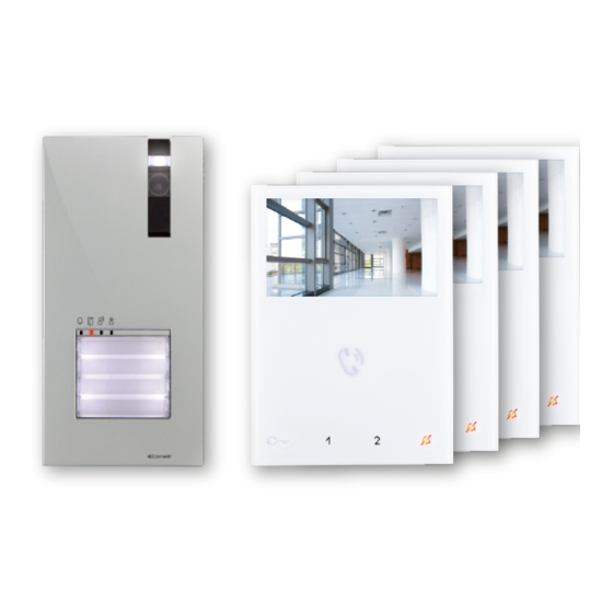
- Page 3 Thank you for purchasing the Hands-Free Kit HFX-7004M! This intercom system uses 2-wire installation and allows you to identify and communicate with callers at the door, from the security and convenience of any room in your home or office. Visitors activate the system by pressing a call pad on the external unit, which sounds a doorbell chime as well as turning on the inside "hands free video monitor".
-
Page 4: Table Of Contents
Contents 4.7 ACTUATOR RELAY MODULE ART. 1256 ..............27 1. Contents of the package ............5 4.7.1 Parts description ..................27 4.7.2 Functions ......................27 2. Parts identification ..............6 4.8 CCTV CAMERA INTERFACE ART. 1409 ..............28 2.1 EX-DSME EXTERNAL UNIT ..................6 4.8.1 Parts description ..................28 2.2 EX-7000H MONITORS ....................7 4.8.2 Operation .....................28 2.2.1 Capacitive-touch keys description ..............8... -
Page 5: Contents Of The Package
×4 ×4 ×16 ×16 dry wall monitor backplate anchors screws 1209/4 - BUS Power supply Technical manual QUICK REFERENCE GUIDE ×1 ×2 Quick reference Guide for Single-User Kit HFX-7004M also available in Passion.Technology. Design. French and Spanish power supply screws... -
Page 6: Parts Identification
2. Parts identification 2.1 EX-DSME EXTERNAL UNIT 3.79 in 1.06 USER 1 USER 2 USER 3 USER 4 1. Die-cast aluminium cover 8. Terminal block M1 2. Camera lighting LED (Can be disabled by setting DIP 7 to ON, see bus line connection page 25 "4.6.2 Function programming"... -
Page 7: Ex-7000H Monitors
2.2 EX-7000H MONITORS 4.52 in 0.83 in 1. Loudspeaker volume control 8. S1 Micro-switches for user code setting f To increase the value, turn clockwise 9. S2 Micro-switches for programming keys and functions DIP 1-2-3-4 for key function programming 2. Brightness control DIP 5-6 access to programming f To increase the value, turn clockwise DIP 7 unused... -
Page 8: Capacitive-Touch Keys Description
2.2.1 Capacitive-touch keys description SPEAKER AND AUDIO ACTIVATION KEY / PAGING CALL KEY / ACTIVATION “HANDS-FREE” MODE Answer call Can be used to activate a conversation with the external unit or to end a conversation. Paging call Internal paging function: can be used to make a paging call to the internal units with the same user code. General paging to another user code: can be used to make a paging call to the internal units with another user code. -
Page 9: 1209/4 Bus Power Supply
2.3 1209/4 BUS POWER SUPPLY 4.17 in 3.52 in Dopo un cortocircuito,per ripristinare l'apparecchio, interrompere l'alimentazione per circa 1 minuto. To reset the operation after a short circuit,cut o mains voltage for about 1 minute. Apres un court circuit, pour remettre en fonction l'appareil, Art.1209/4 interrompre l'alimentation pendant environs une minute. -
Page 10: System Installation
3. System installation 3.1 OPERATING DISTANCES AND SYSTEM LAYOUT A max B max C max Wire Assignment Wire Assignment Wire Type 1,115 feet 557 feet 557 feet CAT5 SINGLE PAIR CABLE 24AWG (340 m) (170 m) (170 m) 1,312 feet 656 feet 656 feet DOUBLE PAIR... -
Page 11: Full System Expansion Diagram
DSME (to be programmed) and the video door expander art. 1405 EX-DSQE EX-DSME 1405 3.1.2 Full system expansion diagram Operating distances EX-7000H EX-7000H EX-7000H EX-7000H 1209/4 EX-DSQE EX-DSQE EX-DSQE expansion external unit expansion external unit expansion external unit 1405 1405 1405 EX-DSME EX-DSME EX-DSME EX-DSME HFX-7004M... -
Page 12: Standard Installation
STANDARD INSTALLATION EX-7000H LEAVE DEFAULT SETTING EX-7000H LEAVE DEFAULT SETTING EX-7000H LEAVE DEFAULT SETTING EX-7000H LEAVE DEFAULT SETTING 34 Vdc 1209/4 LP LP L1 L1 L2 L2 L3 L3 L4 L4 110-240V TO REMOVE 34 Vdc EX-DSME Local lock release button... -
Page 13: Daisy Chain Connection
DAISY CHAIN CONNECTION EX-7000H EX-7000H LEAVE DEFAULT SETTING LEAVE DEFAULT SETTING REMOVE CV5 REMOVE CV5 EX-7000H EX-7000H LEAVE DEFAULT SETTING LEAVE DEFAULT SETTING MAXIMUM 2 MONITORS PER OUTPUT 1209/4 LP LP L1 L1 L2 L2 L3 L3 L4 L4 110-240V REMOVE WHEN LINE IS USED EX-DSME Video Closing Jumper... -
Page 16: Additional Relay Module (Art. 1256) Connection
1200UL 12V~ 120V~ 12/24V 1214/2C AC/DC 1209/4 LP LP L1 L1 L2 L2 L3 L3 L4 L4 110-240V TO REMOVE EX-DSME HFX-7004M Kit Local lock release button For further information see "4.7 Actuator relay module Art. 1256" on page 27... -
Page 17: Assembly Mini Handsfree Art. Ex-7000H Internal Unit
3.2 ASSEMBLY MINI HANDSFREE ART. EX-7000H INTERNAL UNIT optional fixing TO OPEN REMOVING THE TERMINAL INSERTING THE TERMINAL... -
Page 18: Installation Of External Unit Art. Ex-Dsme
3.3 INSTALLATION OF EXTERNAL UNIT ART. EX-DSME CLOCKWISE The camera must not be installed in front of light sources, or in places where the filmed subject is against the light. In dim environments, we recommend additional lighting is provided. 19.68 in CAUTION! 72°... -
Page 19: How To Change The Nameplate/Push Buttons Of The External Unit
Before fixing the screw, make sure that you do not need to program the external unit (See the “4.6 Configuration EX-DSME” on page 25) and make sure that the metal front panel does not rub against other metal parts, with consequent risk of damage to its insulating coating. -
Page 20: Additional Features Programming
4. Additional features programming 4.1 ADDRESSING ART. EX-7000H BY MEANS OF DIP SWITCH f Set the user codes on S1 DIP Switches as indicated in “TAB. A” on page 4.2 CONFIGURATION CAPACITIVE-TOUCH KEYS ART. EX-7000H 4.2.1 Preset functions table S2 DIP-switches DIP 1 DIP 2 DIP 3... -
Page 21: Quick Programming
4.2.2 Quick programming For the quick programming of the following functions: • generic actuator (ACT) • internal intercom calls (INT) • internal paging calls (PAG) • Self ignition main external unit (AI) • Doctor function (D) f Set the S2 DIP-switches combination corresponding to Example Choose S2 DIP-switches combination: the functions that you want to programme for ALL KEYS... -
Page 22: How To Program The Intercom Function
4.2.3.2 HOW TO PROGRAM THE INTERCOM FUNCTION Example: key = general intercom to user code 3 √ Take note of the S1 setting and restore it when programming is complete Enter programming mode f Set S2 DIP switch 5-6 to the combination 01 »... -
Page 23: How To Program The Self Ignition Function
4.2.3.4 HOW TO PROGRAM THE SELF IGNITION FUNCTION Example: √ Take note of the S1 setting and restore it when programming is complete Enter programming mode f Set S2 DIP switch 5-6 to the combination 01 » the Privacy LED flashes 2.1 Choose the function: refer to the “4.2.1 Preset functions table”... -
Page 24: Reset Programming Art. Ex-7000H
4.3 RESET PROGRAMMING ART. EX-7000H Factory settings: • Button functions for the S2 DIP switch 1-2-3-4 combination; DIP OFF • Intercom address absent; • Range function and min./max. addresses absent; • Ringtone reset. Take note of the S2, S1 setting and restore it when programming is complete Carry out steps 1 to 4 DIP ON 5 sec... -
Page 25: Monitor Ringtone Selection Art. Ex-7000H
4.5 MONITOR RINGTONE SELECTION ART. EX-7000H 1. Press and hold for 6 sec. » a confirmation tone will sound » the Privacy LED will flash to indicate “programming” mode. √ The procedure can only take place while the system is in standby; otherwise the Privacy LED will flash 4 times to inform the user that the system is engaged. -
Page 26: Call Address Programming For 2/4 Users
4.6.3 Call address programming for 2/4 users √ Take note of the DIP-switches settings On the S1 DIP-switches, set the code corresponding to the function you want to program. button 1 buttons 1-2 buttons 1-2- Restore enabled with enabled 3-4 enabled default call address with call... -
Page 27: Actuator Relay Module Art. 1256
4.7.1 Parts description 1. JP4 2. JP3 3. JP2 To use the actuator relay module with kit HFX-7004M f Move jumper JP2 to position 2 f Move jumper JP3 to position 2 f Move jumper JP4 to position 2 4. S1 DIP switch for different setting 5. -
Page 28: Cctv Camera Interface Art. 1409
4.8 CCTV CAMERA INTERFACE ART. 1409 Art. 1409 allows to manage analog CCTV camera (up to 3). 1409 4.8.1 Parts description 1. Terminal block M2 for system connection: INA not used GND Common contact V1 S1 Coax input camera 1 V2 S2 Coax input camera 2 V3 S3 Coax input camera 3 2. -
Page 29: Function 2: Actuator With Code Mode
4.8.2.3 FUNCTION 2: ACTUATOR WITH CODE MODE √ NOTE: Before programming the module, see “4.9.2.4 COMPATIBILITY TABLE” By pressing the button programmed as "coded actuator", it is possible to toggle between the different cameras. Microswitch “S1” must be set as shown in following table: CORRESPONDENCE OF 1409 ADDRESS ACTUATOR WITH CODE ON BRACKET DIP 1 DIP 2... -
Page 30: System Function
5. System function f Press the desired key once to activate the function associated with it. Wait for approximately 1 sec. before pressing the same key again. Pressing the same key several times in quick succession will cancel the command. 5.1 PERFORMING CALLS 5.1.1 How to call from the external unit 5.1.2 How to answer a call from an internal unit... -
Page 31: Paging Call
5.2 PAGING CALL 5.2.1 How to initiate a paging call 5.2.2 How to answer a paging call f Press to initiate the all-page chime f Press to answer the paging call » After the chime sounds, a 30 seconds message can be »... -
Page 32: Lock Release Function
5.4 LOCK RELEASE FUNCTION 5.5 ACTIVATION/DEACTIVATION DOCTOR FUNCTION √ During “call in progress” or during Self-ignition. f Press the programmed button for 3 sec to disable/enable the Doctor function. f Press to release the lock. » 3 flashes (every 5 sec.) of the LED indicate that the Doctor »... -
Page 33: Technical Specification
6. Technical specification 6.1 EX-7000H INTERNAL UNITS Display 4.3’’ Color LCD Screen Resolution 480x272pixel Auto Timer (intercom) 300sec Operating Temperature Class B1 normal range indoor 41° F /104° F (5°C / 40°C) Dimensions (with bracket) W×H×D 4.52×6.29×0.83 in (115×160×21.5 mm) Power consumption 10 W MAX 6.2 EX-DSME EXTERNAL UNIT Image Sensor ¼”... -
Page 34: Appendix
7. Appendix 7.1 WARNING WARNING: TO REDUCE THE RISK OF FIRE OR ELECTRIC SHOCK, DO NOT EXPOSE THE MONITOR OR POWER ADAPTER TO WATER OR MOISTURE. CAUTION: DO NOT OPEN. RISK OF ELECTRICAL SHOCK. CAUTION! TO REDUCE RISK OF ELECTRICAL SHOCK, DO NOT REMOVE COVER OR BACK, NO USER SERVICEABLE PARTS INSIDE, REFER SERVICING TO QUALIFIED SERVICE PERSONNEL. -
Page 35: Fcc Class B Notice
• Consult the dealer or an experienced radio or television technician 7.4 GENERAL PRODUCT WARRANTY: For all Comelit Branded Products 2 year manufacturer’s warranty from dealer date of Purchase. Proof of purchase by the dealer in the form of an invoice is necessary for all returns. - Page 37 Merci d'avoir acheté le kit mains libres art. HFX-7004M ! Ce système intercom utilise un installation à 2 câbles et vous permet d'identifier et communiquer avec les personnes qui appellent à la porte. Cela vous assure sécurité et commodité depuis toutes les pièces de votre domicile ou de votre bureau.
- Page 38 Sommaire 4.6.3 Programmation des adresses d’appel pour 2/4 utilisateurs ......60 1. Contenu du colis ................39 4.6.4 Code usager ....................60 4.7 MODULE DU RELAIS DE L'ACTIONNEUR ART. 1256 ..........61 2. Identification des pièces ............40 4.7.1 Description des pièces .................61 2.1 POSTE EXTÉRIEUR EX-DSME ...................40 4.7.2 Fonctions ......................61 2.2 MONITEURES EX-7000H ...................41 4.8 INTERFACE CAMÉRA CCTV ART.
-
Page 39: Contenu Du Colis
EX-7000H - Moniteurs ×16 ×16 ×4 ×4 mur sec boulons moniteur étrier d'ancrage Alimentation électrique BUS - 1209/4 Manuel technique QUICK REFERENCE GUIDE ×1 ×2 alimentation Quick reference Guide for électrique Single-User Kit HFX-7004M also available in Passion.Technology. Design. French and Spanish... -
Page 40: Identification Des Pièces
2. Identification des pièces 2.1 POSTE EXTÉRIEUR EX-DSME 3.79 in 1.06 USER 1 USER 2 USER 3 USER 4 1. Enjoliveur en aluminium moulé sous pression 8. Bornier M1 LL connexion ligne bus 2. LED d'éclairage caméra active sur appel par défaut (Se désactive en réglant le DIP 7 sur ON, page 59 «4.6.2 Fonction RTE entrée ouvre-porte local temporisé... -
Page 41: Moniteures Ex-7000H
2.2 MONITEURES EX-7000H 4.52 in 0.83 in 1. Contrôle du volume du haut-parleur 8. S1 Micro-switches pour le réglage du code d'appel f Tourner dans le sens des aiguilles d’une montre pour 9. S2 Micro-switches pour la programmation des touches et des augmenter la valeur fonctions 2. -
Page 42: Description De La Touche Tactile
2.2.1 Description de la touche tactile TOUCHE D’ACTIVATION PHONIE / D’APPEL DE RADIOMESSAGERIE / D’ACTIVATION DE LA MODALITÉ « MAINS LIBRES » Réponse à un appel Elle peut être utilisée pour activer une conversation entre le poste extérieur ou pour terminer une conversation. Appel de radiomessagerie Elle peut être utilisée pour effectuer un appel de radiomessagerie vers les postes intérieurs avec le même code d’accès. -
Page 43: Alimentation Électrique 1209/4 Bus
2.3 ALIMENTATION ÉLECTRIQUE 1209/4 BUS 4.17 in 3.52 in Dopo un cortocircuito,per ripristinare l'apparecchio, interrompere l'alimentazione per circa 1 minuto. To reset the operation after a short circuit,cut o mains voltage for about 1 minute. Apres un court circuit, pour remettre en fonction l'appareil, Art.1209/4 interrompre l'alimentation pendant environs une minute. -
Page 44: Installation Du Système
3. Installation du système 3.1 DISTANCES OPÉRATOIRES ET DISPOSITION DE LA LIGNE A max B max C max Attribution du câble Attribution du câble Type de câble 1,115 pieds 557 pieds 557 pieds CÂBLE PAIRE CAT5 SIMPLE 24 AWG (340 m) (170 m) (170 m) 1,312 pieds... -
Page 45: Schéma De L'évolution Complète Du Système
EX-DSME et le unité d’extension de la vidéo à la porte art. 1405. EX-DSQE EX-DSME 1405 3.1.2 Schéma de l’évolution complète du système Distances opératoires EX-7000H EX-7000H EX-7000H EX-7000H 1209/4 EX-DSQE EX-DSQE EX-DSQE poste extérieur évolutif poste extérieur évolutif poste extérieur évolutif 1405 1405 1405 EX-DSME EX-DSME EX-DSME EX-DSME HFX-7004M... -
Page 46: Installation Standard
INSTALLATION STANDARD EX-7000H GARDER LE RÉGLAGE PAR DÉFAUT EX-7000H GARDER LE RÉGLAGE PAR DÉFAUT EX-7000H GARDER LE RÉGLAGE PAR DÉFAUT EX-7000H GARDER LE RÉGLAGE PAR DÉFAUT 34 Vdc 1209/4 LP LP L1 L1 L2 L2 L3 L3 L4 L4 110-240V SUPPRIMER 34 Vdc EX-DSME... -
Page 47: Raccordement En Chaîne Bouclée
RACCORDEMENT EN CHAÎNE BOUCLÉE EX-7000H EX-7000H GARDER LE RÉGLAGE GARDER LE RÉGLAGE PAR DÉFAUT PAR DÉFAUT SUPPRIMER SUPPRIMER EX-7000H EX-7000H GARDER LE RÉGLAGE GARDER LE RÉGLAGE PAR DÉFAUT PAR DÉFAUT 2 MONITEURS MAXIMUM PAR SORTIE 1209/4 LP LP L1 L1 L2 L2 L3 L3 L4 L4 110-240V SUPPRIMER LORSQUE LA... -
Page 50: Module De Relais Supplémentaire (Art. 1256)
120V~ 12/24V 1214/2C AC/DC 1209/4 LP LP L1 L1 L2 L2 L3 L3 L4 L4 110-240V SUPPRIMER EX-DSME HFX-7004M Kit Bouton ouvre-porte local. Pour la programmation se reporter à la page 61 "4.7 Module du relais de l'actionneur art. 1256"... -
Page 51: Ensemble Mini Mains Libres Art. Ex-7000H Poste Intérieur
3.2 ENSEMBLE MINI MAINS LIBRES ART. EX-7000H POSTE INTÉRIEUR montage optionnel POUR OUVRIR POUR OUVRIR DÉMONTAGE DU BORNIER MONTAGE DU BORNIER... -
Page 52: Installation Du Poste Extérieur Art. Ex-Dsme
3.3 INSTALLATION DU POSTE EXTÉRIEUR ART. EX-DSME OUVRIR DANS LE SENS DES AIGUILLES D’UNE MONTRE CLOCKWISE La caméra ne doit pas être installée en face de fortes sources de lumière ni dans des lieux où la personne filmée est fortement à contre-jour. Dans des environnements à... -
Page 53: Remplacement De L'étiquette Porte-Noms Ou Les Boutons D'appel Du Poste Extérieur
Avant de fixer la vis, veiller à ce qu’il ne soit pas nécessaire de programmer le poste extérieur (Voir la page 59 “4.6 Configuration de EX-DSME” et à ce que le panneau avant métallique ne frotte pas contre d’autres éléments métalliques, car cela pourrait endommager le revêtement isolant. -
Page 54: Programmation Des Fonctions Supplémentaires
4. Programmation des fonctions supplémentaires 4.1 ADRESSAGE DE L'ART. EX-7000H À L'AIDE DU DIP SWITCH f Régler les codes d'accès sur les DIP switches S1, comme indiqué dans le tableau à la page 60 "TABLEAU A" 4.2 CONFIGURATION DES TOUCHES CAPACITIVES ART. EX-7000H 4.2.1 Fonction de présélection S2 DIP-switches DIP 1... -
Page 55: Programmation Rapide
4.2.2 Programmation rapide Pour la programmation rapide des fonctions suivantes : • actionneur générique (ACT), • appels intercommunicants internes (INT), • appels de radiomessagerie internes (PAG), • poste extérieur principal auto-allumage (AI), • fonction médecin (D) f Régler les combinaison S2 des DIP switches correspondant Exemple aux fonctions que vous souhaitez programmer pour Choisir la combinaison DIP switches S2 :... -
Page 56: Comment Programmer La Fonction Intercommunication
4.2.3.2 COMMENT PROGRAMMER LA FONCTION INTERCOMMUNICATION Exemple : touche = intercommunication générique avec le code d'accès 3 √ Prendre note du réglage S1 et le rétablir au terme de la programmation Entrer le mode de programmation f Régler le DIP switch S2 5-6 sur la combinaison 01 »... -
Page 57: Comment Programmer La Fonction Auto-Allumage
4.2.3.2 COMMENT PROGRAMMER LA FONCTION AUTO-ALLUMAGE Exemple : touche √ Prendre note du réglage S1 et le rétablir au terme de la programmation Entrer le mode de programmation f Régler le DIP switch S2 5-6 sur la combinaison 01 » le LED Privacy clignote 2.1 Choisir la fonction : Consulter le tableau “4.2.1 Fonction de présélection”... -
Page 58: Rétablir La Programmation De L'art. Ex-7000H
4.3 RÉTABLIR LA PROGRAMMATION DE L'ART. EX-7000H Configurations d'usine : • Fonctions des boutons pour la combinaison de DIP switch S2 1-2-3-4 ; DIP OFF • Adresse d'intercommunication absente ; • Plage de fonction et adresses min./max. absentes ; • Remise à zéro de la sonnerie. Prendre note du réglage S2, S1 et le rétablir au terme de la programmation. -
Page 59: Sélection De La Sonnerie Du Moniteur Art. Ex-7000H
4.5 SÉLECTION DE LA SONNERIE DU MONITEUR ART. EX-7000H 1. Appuyer et garder enfoncé pendant 6 sec. » une sonnerie de confirmation retentit » la LED Privacy clignote pour indiquer le mode « programmation » √ La procédure ne peut se dérouler que lorsque le système est en veille ; dans le cas contraire, la LED Privacy clignotera 4 fois afin d'infor- mer l'utilisateur que le système est engagé. -
Page 60: Programmation Des Adresses D'appel Pour 2/4 Utilisateurs
4.6.3 Programmation des adresses d’appel pour 2/4 utilisateurs √ Noter les réglages du DIP-switch Régler DIP-switches correspondant à la fonction à programmer Bouton 1 actif Boutons 1-2 Boutons Rétablissement avec adresse actifs avec 1-2-3-4 actifs réglage d’appel 1 adresses avec adresses d’usine (réglage d’appel 1-2... -
Page 61: Module Du Relais De L'actionneur Art. 1256
2. JP3 3. JP2 Pour utiliser le module du relais de l'actionneur avec le kit HFX-7004M f Placer le cavalier JP2 en position 2 f Placer le cavalier JP3 en position 2 f Placer le cavalier JP4 en position 2 4. -
Page 62: Interface Caméra Cctv Art. 1409
4.8 INTERFACE CAMÉRA CCTV ART. 1409 L'art. 1409 permet de gérer la caméra CCTV analogique (jusqu'à 3). 1409 4.8.1 Description des pièces 1. Bornier M2 pour la connexion du système : INA non utilisé GND Contact commun V1 S1 Entrée coaxiale caméra 1 V2 S2 Entrée coaxiale caméra 2 V3 S3 Entrée coaxiale caméra 3 2. -
Page 63: Fonction 2 : Mode Actionneur Avec Code
4.8.2.3 FONCTION 2 : MODE ACTIONNEUR AVEC CODE √ REMARQUE : avant de programmer le module, consulter le tableau : 63 «4.8.2.4 Tableau de compatibilité» . En appuyant sur le bouton réglé comme « actionneur à code », l'utilisateur peut passer d'une caméra à l'autre. Le microswitch « S1 »... -
Page 64: Fonctions De La Ligne
5. Fonctions de la ligne f Appuyer une fois sur la touche voulue pour activer la fonction qui y est associée. Attendre environ 1 seconde avant d'appuyer à nouveau sur le même bouton. En appuyant plusieurs fois la même touche, la commande sera effacée. -
Page 65: Appel De Radiomessagerie
5.2 APPEL DE RADIOMESSAGERIE 5.2.1 Comment lancer un appel de radiomessagerie 5.2.2 Comment répondre à un appel de radiomessagerie f Appuyer sur pour activer une sonnerie de radiomessagerie f Appuyer sur pour répondre à l'appel de radiomessagerie » Lorsque la sonnerie retentit, un message de 30 secondes »... -
Page 66: Fonction Ouvre-Porte
5.4 FONCTION OUVRE-PORTE 5.5 ACTIVATION / DÉSACTIVATION DU MODE PRIVACY √ Durant un « appel en cours » ou l'auto-allumage. Appuyer sur pour désactiver la sonnerie des appels du poste f Appuyer sur pour ouvrir la porte. extérieur et de la radiomessagerie. »... -
Page 67: Spécifications Techniques
6. Spécifications techniques 6.1 MONITEUR PRINCIPAL EX-7000H Affichage Écran couleur LCD 4,3" Résolution 480x272 pixel Temporisateur automatique (intercom) 300 sec Température de fonctionnement Plage normale classe B1 intérieur de 41°F à 104°F (de 5°C à 40°C) Dimensions (avec support) L × H × P 4,52 × 6,29 × 0,83 po (115 × 160 × 21,5 mm) Consommation 10 W MAX 6.2 POSTE EXTÉRIEUR EX-DSME Capteur d'images ¼”... -
Page 68: Annexe
7. Annexe 7.1 AVERTISSEMENT AVERTISSEMENT : POUR RÉDUIRE LE RISQUE D'INCENDIE OU D'ÉLECTROCUTION, NE PAS EXPOSER LE MONITEUR OU L'ADAPTATEUR À LA PLUIE OU À L'HUMIDITÉ. ATTENTION : NE PAS OUVRIR. RISQUE D'ÉLECTROCUTION. ATTENTION : POUR RÉDUIRE LE RISQUE D'ÉLECTROCUTION, NE RETIRER NI LE COUVERCLE NI LE PANNEAU ARRIÈRE. AUCUNE PIÈCE INTERNE NE PEUT ÊTRE RÉPARÉE PAR L'UTILISATEUR. -
Page 69: Avis Sur Le Fcc Classe B
7.4 GARANTIE GÉNÉRIQUE SUR LE PRODUIT : Tous les produits marqués Comelit (sauf les produits HFX 700, 720 et 900 ) sont couverts par 2 ans de garantie fabricant. Pour tous les retours, un justificatif d'achat de la part du distributeur, sous forme de facture, est nécessaire. - Page 71 Gracias por adquirir el kit manos libres art. HFX-7004M ! Este sistema de intercomunicación utiliza una instalación de 2 cables, y permite identificar y comunicarse con las personas que llaman a la puerta, desde la seguridad y la comodidad de cualquier habitación de su casa u oficina.
- Page 72 Índice 4.7 MÓDULO DE RELÉ DE ACTUADOR ART. 1256 ............95 1. Contenido del paquete ..............73 4.7.1 Descripción de las piezas ................95 4.7.2 Funciones .....................95 2. Identificación de los componentes ..........74 4.8 INTERFAZ DE CÁMARA DE CCTV ART. 1409 ............96 2.1 UNIDAD EXTERNA EX-DSME ..................74 4.8.1 Descripción de las piezas ................96 2.2 MONITOR EX-7000H ....................75 4.8.2 Operación .....................96...
-
Page 73: Contenido Del Paquete
×16 ×16 ×4 ×4 pared seca monitor placa soporte anclajes tornillos 1209/4 - Alimentación del BUS Manual técnico QUICK REFERENCE GUIDE ×1 ×2 Quick reference Guide for Single-User Kit HFX-7004M alimentación tornillos also available in Passion.Technology. Design. French and Spanish... -
Page 74: Identificación De Los Componentes
2. Identificación de los componentes 2.1 UNIDAD EXTERNA EX-DSME 3.79 in 1.06 USER 1 USER 2 USER 3 USER 4 1. Tapa de aluminio fundido 8. Bloque de terminales M1 conexión de la línea de bus 2. LED de iluminación de la cámara (Se puede desactivar entrada del abrepuertas local temporizada configurando el DIP-switch 7 en ON, consulte la página COM entrada común para los contactos RTE y DO... -
Page 75: Monitor Ex-7000H
2.2 MONITOR EX-7000H 4.52 in 0.83 in 1. Control de volumen del altavoz 8. S1 Microinterruptores para definición de códigos de usuario f Para aumentar el volumen, gire en el sentido de las agujas del 9. S2 Microinterruptores para la programación de teclas y reloj. -
Page 76: Descripción De Las Teclas Táctiles Capacitivas
2.2.1 Descripción de las teclas táctiles capacitivas TECLA DE ACTIVACIÓN DE AUDIO / LLAMADA A BUSCAPERSONAS / HABILITAR LA FUNCIÓN “MANOS LIBRES” Llamada de respuesta Puede utilizarse para activar una conversación con la unidad externa o para finalizar una conversación. Llamada a buscapersonas Función de buscapersonas interno: se puede utilizar para realizar una llamada a buscapersonas a las unidades internas con el mismo código de usuario. -
Page 77: Alimentación Del Bus 1209/4
2.3 ALIMENTACIÓN DEL BUS 1209/4 4.17 in 3.52 in Dopo un cortocircuito,per ripristinare l'apparecchio, interrompere l'alimentazione per circa 1 minuto. To reset the operation after a short circuit,cut o mains voltage for about 1 minute. Apres un court circuit, pour remettre en fonction l'appareil, Art.1209/4 interrompre l'alimentation pendant environs une minute. -
Page 78: Instalación Del Sistema
3. Instalación del sistema 3.1 DISTANCIAS DE FUNCIONAMIENTO Y DISEÑO DEL SISTEMA Asignación de Asignación de cables Tipo de cable A máx. B máx. C máx. cables 1.115 pies 557 pies 557 pies CABLE DE PAR CAT5 SIMPLE 24AWG (340 m) (170 m) (170 m) 1.312 pies... -
Page 79: Diagrama De Ampliación De Sistema Máxima
EX-DSME 1405 3.1.3 Diagrama de ampliación de sistema máxima Distancias de funcionamiento EX-7000H EX-7000H EX-7000H EX-7000H 1209/4 EX-DSQE EX-DSQE EX-DSQE unidad externa de ampliación unidad externa de ampliación unidad externa de ampliación 1405 1405 1405 EX-DSME EX-DSME EX-DSME EX-DSME HFX-7004M... -
Page 80: Instalación Estándar
INSTALACIÓN ESTÁNDAR EX-7000H DEJE LA CONFIGURACIÓN PREDETERMINADA EX-7000H DEJE LA CONFIGURACIÓN PREDETERMINADA EX-7000H DEJE LA CONFIGURACIÓN PREDETERMINADA EX-7000H DEJE LA CONFIGURACIÓN PREDETERMINADA 34 Vdc 1209/4 LP LP L1 L1 L2 L2 L3 L3 L4 L4 110-240V RETÍRELOS 34 Vdc EX-DSME Botón de abrepuertas local... -
Page 81: Conexión En Cadena
CONEXIÓN EN CADENA EX-7000H EX-7000H DEJE LA CONFIGURACIÓN DEJE LA CONFIGURACIÓN PREDETERMINADA PREDETERMINADA RETIRE CV5 RETIRE CV5 EX-7000H EX-7000H DEJE LA CONFIGURACIÓN DEJE LA CONFIGURACIÓN PREDETERMINADA PREDETERMINADA MÁXIMO 2 MONITORES POR SALIDA 1209/4 LP LP L1 L1 L2 L2 L3 L3 L4 L4 110-240V RETÍRELOS CUANDO SE UTILICE LA LÍNEA EX-DSME... -
Page 84: Conexión Del Módulo De Relé Adicional (Art. 1256)
12V~ 120V~ 12/24V 1214/2C AC/DC 1209/4 LP LP L1 L1 L2 L2 L3 L3 L4 L4 110-240V RETÍRELOS EX-DSME HFX-7004M Kit Botón de abrepuertas local. Para la programación, consulte la página 95 "4.7 Módulo de relé de actuador Art. 1256"... -
Page 85: Montaje De La Unidad Interna Mini Handsfree Art. Ex-7000H
3.2 MONTAJE DE LA UNIDAD INTERNA MINI HANDSFREE ART. EX-7000H fijación opcional PARA ABRIR EXTRACCIÓN DEL TERMINAL INSERCIÓN DEL TERMINAL... -
Page 86: Instalación De La Unidad Externa Art. Ex-Dsme
3.3 INSTALACIÓN DE LA UNIDAD EXTERNA ART. EX-DSME ABRIR GIRE EN EL SENTIDO DE LAS AGUJAS DEL RELOJ CLOCKWISE No instale la cámara delante de fuentes de luz ni en lugares donde la persona captada quede a contraluz. En entornos oscuros, recomendamos que se proporcione iluminación adicional. -
Page 87: Cómo Cambiar El Tarjetero O Los Botones De Llamada De La Unidad Externa
Antes de fijar el tornillo, asegúrese de que no es necesario programar la unidad externa y compruebe también que el panel frontal de metal no roza con otras piezas de metal, con el consiguiente riesgo de que se produzcan daños en su revestimiento aislante. Para garantizar que el producto siga siendo estanco, asegúrese de realizar correctamente el procedimiento de fijación CORRECTLY! FIJAR... -
Page 88: Programación De Características Adicionales
4. Programación de características adicionales 4.1 ASIGNACIÓN DE DIRECCIÓN ART. EX-7000H MEDIANTE INTERRUPTOR DIP f Defina los códigos de usuario en los interruptores S1 DIP como se indica en “Tabla A - Código de Usuario”. 4.2 CONFIGURACIÓN DE LAS TECLAS TÁCTILES CAPACITIVAS ART. EX-7000H 4.2.1 Función de predefinición S2 DIP-switches DIP 1... -
Page 89: Programación Rápida
4.2.2 Programación rápida Para la programación rápida de las siguientes funciones: • Actuador genérico (ACT) • Llamadas intercomunicantes internas (INT) • Llamadas a buscapersonas internas (PAG) • Unidad externa principal de autoencendido (AI) • Función Doctor (D) f Establezca la combinación de interruptores DIP S2 Ejemplo correspondiente a las funciones que desee programar para Elija la combinación de interruptores DIP S2:... -
Page 90: Cómo Programar La Función Intercom
4.2.3.2 CÓMO PROGRAMAR LA FUNCIÓN INTERCOM Ejemplo: Tecla = intercomunicación general con el código de usuario 3 √ Tome nota del ajuste S1 y restáurelo cuando la programación se complete Entre en el modo de programación f Ajuste el interruptor DIP S2 5-6 en la combinación 01 »... -
Page 91: Cómo Programar La Función De Autoencendido
4.2.3.4 CÓMO PROGRAMAR LA FUNCIÓN DE AUTOENCENDIDO Ejemplo: Tecla √ Tome nota del ajuste S1 y restáurelo cuando la programación se complete Entre en el modo de programación f Ajuste el interruptor DIP S2 5-6 en la combinación 01 » El LED de privacidad parpadea 2.1 Elija la función: consulte la tabla “4.2.1 Función de predefinición”... -
Page 92: Restablecimiento De La Programación Art. Ex-7000H
4.3 RESTABLECIMIENTO DE LA PROGRAMACIÓN ART. EX-7000H Configuraciones de fábrica: • Funciones de botones para la combinación de los interruptores DIP S2 1-2-3-4 DIP OFF • Ausencia de dirección de intercomunicación • Ausencia de función de rango y direcciones mín./máx •... -
Page 93: Selección Del Tono De Llamada Del Monitor De Art. Ex-7000H
4.5 SELECCIÓN DEL TONO DE LLAMADA DEL MONITOR DE ART. EX-7000H 1. Pulse y mantenga pulsado durante 6 segundos. » Se oirá un tono de confirmación. » El LED de privacidad parpadeará para indicar el modo de “programación”. √ El procedimiento solo puede realizarse mientras el sistema está en espera; de lo contrario, el LED de privacidad parpadeará 4 veces para informar al usuario de que el sistema está... -
Page 94: Programación De Las Direcciones De Llamada Para 2/4 Usuarios
4.6.3 programación de las direcciones de llamada para 2/4 usuarios √ Anotar la configuración del DIP-switch. Configurar el código correspondiente a la función que se desea programar mediante los DIP-switches S1. Pulsadores Restab- Pulsador 1 Pulsadores 1-2-3-4 lecimiento activado con 1-2 activados activados con predefinido... -
Page 95: Módulo De Relé De Actuador Art. 1256
1. JP4 2. JP3 3. JP2 Para usar el módulo de relé de actuador con el kit HFX-7004M f Desplace el puente JP2 a la posición 2 f Desplace el puente JP3 a la posición 2 f Desplace el puente JP4 a la posición 2 4. -
Page 96: Interfaz De Cámara De Cctv Art. 1409
4.8 INTERFAZ DE CÁMARA DE CCTV ART. 1409 El Art. 1409 permite gestionar cámaras de CCTV analógicas (hasta 3). 1409 4.8.1 Descripción de las piezas 1. Bloque de terminales M2 para conexión de sistema: INA no se utiliza GND Contacto común V1 S1 Entrada coaxial de cámara 1 V2 S2 Entrada coaxial de cámara 2 V3 S3 Entrada coaxial de cámara 3... -
Page 97: Función 2: Modalidad Actuador Con Código
4.8.2.3 FUNCIÓN 2: MODALIDAD ACTUADOR CON CÓDIGO √ NOTA: Antes de programar el módulo, consulte “4.8.2.4 TABLA DE COMPATIBILIDAD” Al pulsar el botón programado como "actuador con código", es posible cambiar entre las distintas cámaras El microinterruptor “S1” debe ajustarse como se muestra en la siguiente tabla: Correspondencia de la dirección 1409 del actuador con código en el soporte DIP 1 DIP 2... -
Page 98: Función Del Sistema
5. Función del sistema f Pulse la tecla deseada una vez para activar la función asociada a ella. Espere aproximadamente 1 segundo antes de volver a pulsar la misma tecla. El comando se cancelará si la misma tecla se pulsa varias veces en sucesión rápida. 5.1 REALIZACIÓN DE LLAMADAS 5.1.1 Cómo llamar desde la unidad externa 5.1.2 Cómo responder a una llamada de una unidad interna... -
Page 99: Llamada A Buscapersonas
5.2 LLAMADA A BUSCAPERSONAS 5.2.1 Cómo iniciar una llamada a buscapersonas 5.2.2 Cómo responder a una llamada a buscapersonas f Pulse para iniciar el timbre de buscapersonas. f Pulse para responder a la llamada a buscapersonas. » Tras sonar el timbre, se puede enviar un mensaje de 30 »... -
Page 100: Función De Abrepuertas
5.4 FUNCIÓN DE ABREPUERTAS √ Durante una “llamada en curso” o durante el autoencendido. f Pulse para liberar el cierre. » El LED se iluminará en la unidad externa. 5.5 ACTIVACIÓN / DESACTIVACIÓN DEL MODO DE PRIVACIDAD Pulse a fin de desactivar/activar el tono de llamada para llamadas de la unidad externa y llamadas a buscapersonas. »... -
Page 101: Especificaciones Técnicas
6. Especificaciones técnicas 6.1 MONITOR PRINCIPAL EX-7000H Visualización Pantalla LCD de 4,3’’ en color Resolución 480x272 píxeles Temporizador automático 300 seg. (intercomunicación) Temperatura de funcionamiento Margen normal en interiores, Clase B1, 41 °F /104 °F (5 °C / 40 °C) Dimensiones (con soporte) An×Al×Pr 4,52×6,29×0,83 pulg. -
Page 102: Apéndice
7. Apéndice 7.1 ADVERTENCIA ADVERTENCIA: PARA REDUCIR EL RIESGO DE INCENDIOS O DESCARGAS ELÉCTRICAS, NO EXPONGA EL MONITOR NI EL ADAPTADOR DE ALIMENTACIÓN AL AGUA NI A LA HUMEDAD. ATENCIÓN: NO LO ABRA. RIESGO DE DESCARGAS ELÉCTRICAS. ATENCIÓN PARA REDUCIR EL RIESGO DE DESCARGAS ELÉCTRICAS, NO QUITE LA CUBIERTA NI LA PARTE TRASERA. EN EL INTERIOR NO HAY PIEZAS QUE EL USUARIO PUEDA REPARAR. -
Page 103: Aviso De Fcc Clase B
7.4 GARANTÍA GENERAL DEL PRODUCTO: Para todos los productos de la marca Comelit (excluidos los productos HFX 700, 720 y 900): garantía de 2 años del fabricante a partir de la fecha de compra del distribuidor. Para todas las devoluciones se necesita una prueba de compra por parte del distribuidor en forma de factura. - Page 104 w w w . c o m e l i t g r o u p . c o m Via Don Arrigoni, 5 - 24020 Rovetta (BG) - Italy...