Advertisement
Available languages
Available languages
Advertisement
Chapters

Related Manuals for Dynacord CMS3


Summary of Contents for Dynacord CMS3
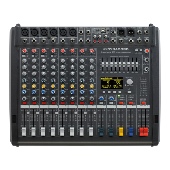
- Page 1 CMS 600-3 COMPACT MIXING SYSTEM Owner‘s Manual | Bedienungsanleitung...
-
Page 3: Table Of Contents
CONTENTS INHALT ....... . 5 ........39 NTRODUCTION INFÜHRUNG Scope of Delivery, Unpacking and Inspection . - Page 4 IMPORTANT SAFETY INSTRUCTIONS The lightning flash with arrowhead symbol, within an equilateral triangle is intended to alert the user to the presence of uninsulated „dangerous voltage“ within the product’s enclosure that may be of sufficent magnitude to constitute a risk of electric shock to per- sons.
-
Page 5: Introduction
Because of its comprehensive set of integrated features – like equalizer and effects units – the Compact Mixing System DYNACORD CMS 600-3 is a professional mixer of- Do not cover the ventilation louvers in the bottom plate fering an optimized all-in-one solution for basically any of the appliance. -
Page 6: Controls, Indicators And Connections
2 Controls, Indicators and Connections 2.1 Input Mono HINT: When connecting signal sources, please make sure to set the corresponding channel faders or at least the master faders to their minimum positions or engage the STANDBY switch. This will save you, your audience, and the equipment from extensive wear from unpleasant pops. - Page 7 HINT: Please, do not connect E-guitars or E-basses with passive, high impedance outputs directly to a LINE input. The LINE inputs of the CMS – like the Line level inputs of mixers from other manufacturers – are designed for the connection of the relatively low source impedance of electronic instruments. The reproduction of the instrument’s original sound characteristics will be unsatisfactory.
- Page 8 sound. You should use the natural reproduction as an orientation mark and rely on your musically trained ear. The moderate use of the MID control is the best remedy to avoid acoustical feedback. Es- pecially in this frequency range you should try to avoid excessive enhancement. Lowering the level more or less in this band will provide you with high amplification rates without feedback.
- Page 9 11 - PFL Engaging the PFL button routes the audio signal to the headphones bus, so that it is present at the phones output con- nector. The meter instrument in the master section is simultaneously switched, so that the left LED-chain indicates the level of the actually chosen channel (in dBu), which allows optimally matching the level of the signal source.
-
Page 10: Input Stereo
2.2 Input Stereo Since most features – AUX/MON controls and channel faders – of the STEREO INPUTS are virtually identical to the ones of the MONO INPUTS we will not discuss their functioning in detail again. Thus, in the following we only point out the differences and like to ask you to refer to the analogous para- graphs within this owner’s manual describing the mono inputs. - Page 11 achieved at the 0 dB mark. The control offers level reduction of -10 dB and an amplification of +20 dB. This range allows the connection of most professional, semi professional, and hi-fi sound sources. For further details on how to set the TRIM LINE CD control, please refer to the description of the GAIN control in monaural channels.
-
Page 12: Aux To Fx 2
2.3 FX 1/2 The CMS offers two independently controllable, identically configured 24-bit stereo effect units – FX 1 and FX 2. Each unit provides 100 program presets, which are selected by the use of the UP/DOWN buttons. Parameters of presets can be edited and stored as User Preset (101 - 120), see page 22 for details. - Page 13 25 - FX 1/2 FOOTSW. Phone jack for the connection of an optionally available DYNACORD FS 11 (DC-FS11) footswitch to switch the effect mode of the internal FX units on or off. To accomplish this function, the FX 1 and FX 2 ON switches have to be engaged.
-
Page 15: Aux
2.4 AUX Generally, the AUX channel is used for the connection of an additional, external FX unit. Depending on the setting of the AUX 1/2 POST button, it is also possible to configure the bus for monitoring purposes. Additionally the AUX channel is available at the DIGITAL AUDIO INTERFACE (channel USB 3). - Page 17 38 - MASTER LED-DISPLAY The CMS offers two 10-segment LED-chains for optical monitoring the output levels of the L/R master signals. The indi- cation range of the LED-meter is 40 dB, indicating the levels that are present at the master outputs in dBu. The meter’s 0 dB mark is referenced to a 0 dBu output signal at the mixer output.
-
Page 19: Display With Function Keys
47 - PHONES This control sets the volume of the headphones connected. CAUTION: Make sure to set the control to its minimum position before connecting headphones. Permanent hear- ing loss may occur if headphones are used at high volume. 48 - REC SEND L/R These RCA-type connectors carry the pre fader master L/R signal. -
Page 20: Rear Panel
Menu mode Press the MENU/ENTER rotary encoder in effect mode to enter the menu mode. In menu mode the display indicates the function being executed for each function key. 53 - MENU/ENTER Use the MENU/ENTER rotary encoder in menu mode for menu navigation. In effect mode the MENU/ENTER rotary en- coder has no function. -
Page 21: Display & Functions
3 Display & functions The CMS includes a premium OLED display. Compared to general LC displays the OLED display is brighter, has a greater contrast ratio and a wider viewing angle. 3.1 Effect mode The start screen appears after switching the CMS on. Af- Number Description ter a few seconds the default effect for FX 1 &... -
Page 22: Main Menu
ENU STRUCTURE Illustration 3-5: Menu structure of CMS PLAY 11-12 MIDI PEAK AUX BRIGHT HALL MONO DELAY Main Menu Large Hall 3 230 ms 40% Edit FX 1 Device Setup FX Control Setup Footswitch Ctrl. Edit FX 2 Display Brightness TAP Button Ctrl. -
Page 23: Aux Mode
This dialog is used to change the user preset‘s descrip- all AUX controls to their center position, the master mix tion. Turn the MENU/ENTER rotary encoder to the left or is also present on the monitor bus, giving you the oppor- right to edit the highlighted character. -
Page 24: Footswitch Ctrl
Table 3-13: FX Control Setup parameter ENTER rotary encoder to apply the selected brightness. Pressing the BACK function key returns to the menu. Parameter Description Pressing the ESC function key returns to effect mode. Footswitch Ctrl. Select FX 1, FX 2 or FX 1+2 to control one or both effect units using a footswitch. -
Page 25: Effects
ed, pressing the MENU/ENTER rotary encoder resets the Table 3-15: Factory settings CMS to its factory settings. If NO has been selected, all Parameter Value parameters stay unchanged and the display returns to the menu. Pressing the BACK function key returns to the AUX Routing menu. -
Page 26: Digital Audio Interface
For using your CMS in the Cubase software execute follo- wing steps: Start the Cubase LE software. Select Devices > Configure Devices. The Configure Devices dialog appears. Select VST-Audiosystem in the left section of the dialog. Select the ASIO driver„ASIO for DYNACORD USB-... -
Page 27: Status Display
Synthesizer (illustration shows CMS 1000-3) Mac. In the system settings of your PC/Mac, select the CMS (DYNACORD USB-AUDIO) as the playback device. Audio signals are output from the PC/Mac through input channels USB 1-2 of the CMS. You can use the fader to control the volume, like it is explained in detail in the In- put Stereo section on page 10. -
Page 28: Example Of Usage (Recording)
4.6 Example of usage (Recording) keyboard to the MIDI IN jack and select the MIDI INTER- FACE as input for the tone generator in the software application. The computer-generated sounds are trans- In the following application, your PC/Mac is used for mitted over one of the two USB stereo channel strips recording while the CMS functions as premium A/D con- back to the CMS. -
Page 29: Setting Up A Standard Pa
5 Setting up a standard PA 5.1 Cabling The mains supply cord comes with the CMS. The quality is always the better solution. Today’s modern audio of all other cables lies in your responsibility. Carefully equipment – like amplifiers, equalizers, FX units, mixing chosen high quality cables are the best precaution to pre- consoles, and even some keyboards –... -
Page 30: Soundcheck
between the two speaker “clusters” – the more Connect all microphones preferably to the monau- compact the sound. ral inputs of the CMS and keyboards and other com- parable sound sources to the rest of the available Try to avoid the positioning of the main loudspeak- inputs. - Page 31 ONITOR Set the MON fader located in the master section to the -5 dB mark. Set the MON controls of all input channels accord- ing to your personal taste. Use the FX 1/2 to MON control to add the effect mix to the monitor mix, without influencing the master mix.
-
Page 32: Setup Examples
6 Setup examples 6.1 CMS with D-Lite activeone Illustration 6-1: CMS with D-Lite activeone (2 x D 8A, 1 x PowerSub 212) as main PA, 1 x D 8A used as monitor... -
Page 33: Cms With D-Lite Activetwo
6.2 CMS with D-Lite activetwo Illustration 6-2: CMS with D-Lite activetwo (2 x D 8A + 2 x PowerSub 112) as main PA, 1 x D 8A used as monitor... -
Page 34: Cms With D-Lite Activefour
6.3 CMS with D-Lite activefour Illustration 6-3: CMS with D-Lite activefour (2 x D 11A + 2 x PowerSub 212) as main PA, 1 x D 11A used as monitor... -
Page 35: Cms With Xa-2 System
6.4 CMS with Xa-2 system Illustration 6-4: CMS with Xa-2 system (2 x FX 12, 4 x FX20, 2 x Xa 4000) as main PA, 1 x D 8A used as monitor Xa 4000 Xa 4000... -
Page 36: Cms With Corus-Evolution System
6.5 CMS with CORUS-Evolution system Illustration 6-5: CMS with CORUS-Evolution system (2 x C 25.2, 2 x Sub 2.18, 2 x LX 3000, 1 x DSP 260) as main PA, 1 x D 11A used as monitor LX 3000 LX 3000 DSP 260... - Page 38 WICHTIGE SICHERHEITSHINWEISE Das Blitzsymbol innerhalb eines gleichseitigen Dreiecks soll den Anwender auf nicht isolierte Lei- tungen und Kontakte im Geräteinneren hinweisen, an denen hohe Spannungen anliegen, die im Fall einer Berührung zu lebensgefährlichen Strom- schlägen führen können. Das Ausrufezeichen innerhalb eines gleichseitigen Dreiecks soll den Anwender auf wichtige Bedie- nungs- sowie Servicehinweise in der zum Gerät gehörenden Literatur aufmerksam machen.
-
Page 39: Einführung
Das Compact Mixing System CMS 600-3 ist ein profes- sionelles Mischpult das aufgrund der vielen integrierten Features, wie Equalizer und Effektgeräte, eine optimierte Hinweise zur Garantie finden Sie auf www.dynacord.com Komplettlösung für unterschiedlichste Einsatzgebiete darstellt. Das CMS-Pult kann äußerst zeitsparend und einfach aufgebaut werden, da komplizierte Rack-Konfigu- ration und störanfällige Verkabelung mehrerer Ein-... -
Page 40: Bedienelemente Und Anschlüsse
2 Bedienelemente und Anschlüsse 2.1 Input Mono HINWEIS: Achten Sie bitte darauf, dass vor dem Anschluss von Signalquellen die jeweiligen Kanalregler, mindestens jedoch die beiden Masterregler, geschlossen sind, oder der STANDBY-Schalter gedrückt ist. Sie ersparen sich selbst, Ihrem Publikum und Ihrem Equipment unnötige Beanspruchungen durch Knackgeräusche. - Page 41 HINWEIS: Betreiben Sie bitte keine E-Gitarre bzw. E-Bass mit passiver Elektronik und hochohmigem Ausgang direkt an einem Mischpult LINE-Eingang. Diese Eingänge sind typischerweise, auch bei allen andern Herstellern, für relativ niedrige Quellimpedanzen ausgelegt, wie sie elektronische Geräte aufweisen. Das Klangergebnis wird unbefriedigend sein und der Klangcharakteristik der Instrumente nicht gerecht werden.
- Page 42 5 - K (HI-, MID-, LO-R LANGREGELUNG EGLER Die Klangregelung erlaubt eine sehr umfangreiche und effektive Beeinflussung des Eingangssignals innerhalb unterschiedlicher Frequenzbereiche. Eine Drehung der Klangregler nach rechts bewirkt eine Anhebung/Verstärkung des entsprechenden Frequenzbereichs. Eine Drehung nach links bewirkt eine Absenkung/Abschwächung des entsprechenden Frequenzbereichs.
- Page 43 9 - PAN-R EGLER Dieser Regler bestimmt die räumliche Position des Eingangssignals im Stereobild. In Mittelstellung wird das Signal zu gleichen Teilen auf die beiden Summen L und R aufgeteilt. Die PAN-Regler-Stufe ist so ausgelegt, dass egal wo Sie den PAN-Regler hindrehen, die Gesamtlautstärke im Stereo-Klangbild erhalten bleibt.
-
Page 44: Input Stereo
2.2 Input Stereo Viele Funktionsgruppen wie AUX-Regler, MON-Regler und Fader sind im Stereo-Eingang identisch zum Mono-Eingang aufgebaut und wurden dort bereits ausführlich erklärt. Wir wollen hier nur die wesent- lichen Unterschiede herausarbeiten. Ansonsten dürfen wir Sie auf den jeweiligen Abschnitt im Kapitel Input Mono verweisen. - Page 45 15 - TRIM LINE CD-R EGLER Mit diesem Regler wird das Signal an den Klinken-Eingängen bzw. Cinch-Eingängen im Stereokanal an den internen Ar- beitspegel des Mischpultes angepasst. Der Regelbereich liegt bei 30 dB. Die Unity-Gain-Position, also 0 dB Durchgangs- verstärkung, ist hier bei der Markierung 0 dB. Sie können mit diesem Regler das Signal um bis zu 10 dB abschwächen bzw.
- Page 46 2.3 FX 1/2 Das CMS ist mit zwei unabhängig regelbaren 24bit-Stereo-Effektteilen FX 1 und FX 2 ausgestattet. Die beiden Effektteile sind völlig identisch aufgebaut. Es stehen je Effektsektion 100 Presets zur Auswahl, die über das Display selektiert werden. Darüber hinaus besteht die Möglichkeit ausgehend von den Preset-Programmen einzelne Parameter der Effekte zu verändern und in 20 User-Presets (Programm- nummer 101-120) abzuspeichern.
- Page 47 Die Klinkenbuchse FX 1/2 FOOTSW. dient zum Anschluss eines Fußschalters FS 11 (DC-FS11) aus dem Zubehörpro- gramm von DYNACORD. Die eingebauten Effektteile können damit ein- und ausgeschaltet werden. Zur Fernsteuerung mittels Fußschalter müssen die Effektgeräte über die FX 1 ON- bzw. FX 2 ON-Schalter aktiviert sein.
-
Page 49: Aux
2.4 AUX Der Kanalzug AUX kann beliebig zum Monitoring oder als FX Send (bei Wahl von AUX POST) betrieben werden. Zusätz- lich ist AUX auf dem Aufnahmekanal 3 des DIGITAL AUDIO INTERFACE verfügbar. 30 - AUX SEND-B UCHSE Hier schließen Sie entweder ein Effektgerät oder im Monitorbetrieb eine Monitorendstufe bzw. einen Aktivmonitor an. Der Pegel an dieser Buchse kann in einem weitem Bereich bis maximal +20 dBu über den AUX-Fader geregelt werden. - Page 51 38 - MASTER-A USSTEUERUNGSANZEIGE Die Aussteuerungsanzeige des CMS besteht aus zwei LED-Ketten für den rechten bzw. linken Kanal mit je 10 LEDs pro Kette. Der Anzeigebereich liegt bei 40 dB und stellt den Pegel in dBu an den Master-Ausgängen dar. D.h. zeigt die An- zeige 0 dB an, so stehen am Mischpultausgang aktuell 0 dBu.
- Page 53 46 - PHONES-B UCHSE Diese Stereo-Klinkenbuchse (6,3 mm) ist für Kopfhörer von 32 bis 600 Ohm geeignet. Hier kann das PFL-Signal abgehört werden, wenn eine PFL-Taste gedrückt ist. Ist keine PFL-Taste gedrückt, führt der PHONES-Ausgang das MASTER A L/ R-Signal. Da der Ausgang kurzschlussfest ist, können Sie auch Kopfhörer oder InEar-Monitorsysteme mit einer Impedanz unter 32 Ohm anschließen.
-
Page 54: Display Mit Funktions-Tasten
2.7 DISPLAY mit Funktions-Tasten 52 - D ISPLAY MIT UNKTIONSTASTEN Zum Schutz vor Verkratzen ist das Displayglas bei Auslieferung mit einer Folie abgedeckt. Ziehen Sie diese bitte ab. Effekt-Betriebsart Das Display zeigt in der Effekt-Betriebsart die aktuell eingestellte Programmnummer des jeweiligen Effektteils an. Mit den vier Tasten unter dem Display werden die Effektprogramme angewählt. - Page 55 56 - N (POWER) ETZSCHALTER Netzschalter zum Ein- und Ausschalten des Gerätes. Das Gerät ist betriebsbereit, wenn das Display aufleuchtet. Achten Sie bitte darauf, dass beim Anschalten des Gerätes die beiden MASTER-Fader geschlossen sind, oder der STANDBY- Schalter gedrückt ist. Sie ersparen sich selbst, Ihrem Publikum und Ihrem Equipment unnötige Beanspruchungen durch ungewollte Signalverstärkung oder sogar Rückkopplungen.
-
Page 56: Display & Funktionen
3 Display & Funktionen Das CMS ist mit einem hochwertigen OLED-Display ausgestattet. Im Vergleich zu üblichen LC-Displays sind OLED-Dis- plays wesentlich heller, kontrastreicher und sind unabhängig vom Blickwinkel optimal abzulesen. 3.1 Effekt-Betriebsart Nach dem Einschalten des CMS wird der Startbildschirm Nummer Beschreibung angezeigt. -
Page 57: Fx2 Start Preset
ENÜ Abbildung 3-5: Menüstruktur des CMS PLAY 11-12 MIDI PEAK AUX BRIGHT HALL MONO DELAY Main Menu Large Hall 3 230 ms 40% Edit FX 1 Device Setup FX Control Setup Footswitch Ctrl. Edit FX 2 Display Brightness TAP Button Ctrl. AUX Mode Screensaver FX1 Start Preset... - Page 58 Im Set FX Name Dialog kann die Bezeichung des User Abbildung 3-10: POST-Modus im AUX Mode Dialog Presets eingegeben werden. Drehen Sie den MENU/EN- AUX Mode TER-Drehencoder nach links oder rechts, um das mit dem Cursor markierte Zeichen zu ändern. Drücken des MENU/ ENTER-Drehencoders übernimmt das gewählte Zeichen und bewegt den Cursor um eine Stelle nach rechts.
- Page 59 Im FX Control Setup Dialog kann durch Drehen des um die Helligkeit zu verringern. Drehen Sie den MENU/ MENU/ENTER-Drehencoders ein Eintrag in der linken ENTER-Drehencoder nach rechts, um die Helligkeit zu er- Spalte markiert und durch Drücken des MENU/ENTER- höhen. Drücken des MENU/ENTER-Drehencoder über- Drehencoders der entsprechende Wert in der rechten nimmt die gewählte Helligkeit.
-
Page 60: Effekte
Play 11-12 at STDBY bei Wahl von NO wird der Rücksetzvorgang abgebrochen. Drücken der BACK-Funktionstaste führt in den Device Um im STANDBY-Betrieb des CMS über den Eingang 11- Setup Dialog zurück. Drücken der ESC-Funktionstaste 12 (bzw. CD 3-4) Hintergrundmusik einspielen zu können, führt in die Effekt-Betriebsart zurück. -
Page 61: Digital Audio Interface
Wählen Sie im Abschnitt Geräte den Eintrag VST- NSTALLATION Audiosystem. Wählen Sie als ASIO-Treiber den Eintrag „ASIO for Legen Sie die mitgelieferte DVD ein. DYNACORD USB-AUDIO“ und schließen Sie den Öffnen Sie das für Ihr Betriebssystem passende Dialog durch Klick auf OK. Unterverzeichnis im Verzeichnis /Cubase_LE. HINWEIS:... -
Page 62: Funktionsanzeige Im Display
4.4 PC-MIDI-Interface Das CMS stellt Ihnen ein vollwertiges PC-MIDI-Interface geeignete Auswahl der MIDI-Kanäle vermeiden, beachten zur Verfügung. Der im PC/Mac als DYNACORD USB-MIDI Sie hierzu Abschnitt “FX Control Setup” auf Seite 58 und bezeichnete Port kann überall ausgewählt werden, wo die Dokumentation der von Ihnen verwendeten Software. -
Page 63: Anwendungsbeispiele (Wiedergabe)
Sollen MIDI-Daten mit der Medienwiedergabe von Windows an externen Geräten wiedergegeben wer- den, müssen Sie in der Windows-Systemsteuerung den Dialog "Sounds und Audiogeräte" öffnen und das Standardgerät der MIDI-Musikwiedergabe auf DYNACORD USB-MIDI umstellen. 4.5 Anwendungsbeispiele (Wiedergabe) Bei Verwendung des DIGITAL AUDIO INTERFACE als... -
Page 64: Midi-Klangerzeuger Und Multieffektgerät
E-Gitarre) nur gering oder gar nicht auf die Beschallungs- HINWEIS: Beachten Sie, dass bei der Aufnahme die anlage gegeben werden. Umgekehrt klingen Aufnahmen, Signale der Raummikrofone nicht in die die nur über ein Raummikrofon gemacht wurden, sehr Beschallungsmischung mit eingehen dür- indirekt und lassen gerade beim Gesang Klarheit und Ver- fen, damit es nicht zu Rückkopplungen ständlichkeit vermissen. -
Page 65: Aufbau Einer Standard-Pa
5 Aufbau einer Standard-PA 5.1 Verkabelung Das Netzkabel haben Sie mit dem CMS erhalten. Für alle meisten Audiogeräte wie Endstufen, Equalizer, Effekt- anderen Kabel sind Sie selbst verantwortlich und je sorg- geräte, Mischpulte und auch einige Keyboards verfügen fältiger Sie bei der Auswahl der Kabel vorgehen, um so über symmetrisch aufgebaute Eingänge bzw. -
Page 66: Soundcheck
schrauben oder, wenn dies nicht ausreichend ist Geräte wie in den Aufbaubeispielen gezeigt. bzw. keine Bassboxen benötigt werden, Hoch- Beachten Sie dabei immer die Bedienungsanlei- ständer. tungen aller verwendeten Geräte. Achten Sie darauf, dass Sie dabei links und rechts nicht vertauschen. Stellen Sie die linke und rechte PA-Boxen-Kombina- tion nur so weit auseinander wie nötig. - Page 67 Kanälen nur bei sehr hohen Dynamikspitzen auf- leuchtet. Bei häufigem Aufleuchten drehen Sie die FX-Regler in allen beteiligten Eingangskanälen in etwa gleichem Maß zurück. ONITORMIX Ziehen Sie den MON-Fader im Masterbereich auf die -5 dB Positon. Passen Sie den Monitormix über die MON-Regler in den belegten Eingangskanälen so an, dass die Abmi- schung der Klangquellen Ihrer Vorstellung ent- spricht.
-
Page 68: Aufbaubeispiele
6 Aufbaubeispiele 6.1 CMS mit D-Lite activeone Abbildung 6-1: CMS mit D-Lite activeone (2 x D 8A, 1 x PowerSub 212) als Haupt-PA, zusätzlich 1 x D 8A für den Monitorweg... -
Page 69: Cms Mit D-Lite Activetwo
6.2 CMS mit D-Lite activetwo Abbildung 6-2: CMS mit D-Lite activetwo (2 x D 8A + 2 x PowerSub 112) als Haupt-PA, zusätzlich 1 x D 8A für den Monitorweg... -
Page 70: Cms Mit D-Lite Activefour
6.3 CMS mit D-Lite activefour Abbildung 6-3: CMS mit D-Lite activefour (2 x D 11A + 2 x PowerSub 212) als Haupt-PA, zusätzlich 1 x D 11A für den Monitorweg... -
Page 71: Cms Mit Xa-2 System
6.4 CMS mit Xa-2 System Abbildung 6-4: CMS mit Xa-2 System (2 x FX 12, 4 x FX20, 2 x Xa 4000) als Haupt-PA, zusätzlich 1 x D 8A für den Monitorweg Xa 4000 Xa 4000... -
Page 72: Cms Mit Corus-Evolution System
6.5 CMS mit CORUS-Evolution System Abbildung 6-5: CMS mit CORUS-Evolution System (2 x C 25.2, 2 x Sub 2.18, 2 x LX 3000, 1 x DSP 260) als Haupt-PA, zusätzlich 1 x D 11A für den Monitorweg LX 3000 LX 3000 DSP 260... -
Page 73: Specifications
7 Specifications Property CMS 600-3 Order No. F01U213891 DC-CMS600-3-UNIV Channels 4 +2 + 2 MIC/Line-Mono MIC/Line-Mono / USB-Stereo (Super Channel) Line L-R / CD-IN-Stereo Auxiliarys (AUX, MON) Pre/Post switchable, Pre MIC GAIN (LINE -20 dB) +10 to +60 dB TRIM LINE/CD (Stereo) -10 to +20 dB THD, at 1 kHz, MBW = 80 kHz MIC input to Master A L/R outputs, +16 dBu, typical... - Page 74 Property CMS 600-3 AD/DA Conversion 24-bit Sampling Rate 44.1 / 48 / 88.2 / 96 kHz PC Interface USB2.0, Female Type B MIDI Interface 5-pin DIN connector, In / Out Protection Mixer Outputs (Relay controlled) AUX, MON, MASTER A L/R Switching Mode Power Supply (µC controlled) Mains Over/Undervoltage Phantom Power, switchable...
-
Page 75: Dimensions
7.1 Dimensions... -
Page 76: Block Diagram
7.2 Block Diagram... - Page 77 Trademarks. • Microsoft, Windows, Windows XP, Windows Vista and Windows 7 are either registered trademarks or trademarks of Microsoft Corporation in the United States and/or other countries • Apple, Macintosh, Mac OS and Mac OS X are trademarks of Apple Inc., registered in the United States and other countries •...
- Page 78 Notes...
- Page 80 DYNACORD 12000 Portland Avenue South, Burnsville, MN 55337, USA Europe, Africa, and Middle East only. For customer orders, contact Customer Service at: Phone: +1 952/844-4051, Fax: +1 952/884-0043 +49 9421-706 0 Fax: +49 9421-706 265 Asia & Pacific only. For customer orders, contact Customer Service at: www.dynacord.com...