Table of Contents
Advertisement
www.nordictrack.com
Model No. 29835.1
Serial No.
USER'S MANUAL
Write the serial number in the space
above for reference.
Serial Number Decal
(under frame)
ACTIVATE YOUR
WARRANTY
To register your product and
activate your warranty today,
contact Customer Service.
CUSTOMER SERVICE
Call toll-free 1-888-936-4266
Mon.–Fri. 7:30 a.m.–4:30 p.m. ET
(excluding holidays)
or email us at
customerservice@iconcanada.ca
Please do not contact the store.
CAUTION
Read all precautions and instruc-
tions in this manual before using
this equipment. Keep this manual
for future reference.
Advertisement
Table of Contents

Related Manuals for NordicTrack 29835.1


Summary of Contents for NordicTrack 29835.1
- Page 1 Model No. 29835.1 Serial No. USER’S MANUAL Write the serial number in the space above for reference. Serial Number Decal (under frame) ACTIVATE YOUR WARRANTY To register your product and activate your warranty today, contact Customer Service. CUSTOMER SERVICE Call toll-free 1-888-936-4266 Mon.–Fri.
-
Page 2: Table Of Contents
TABLE OF CONTENTS WARNING DECAL PLACEMENT ............. . .2 IMPORTANT PRECAUTIONS . -
Page 3: Important Precautions
IMPORTANT PRECAUTIONS WARNING: To reduce the risk of serious injury, read all important precautions and instructions in this manual and all warnings on your elliptical before using your elliptical. ICON assumes no responsibility for personal injury or property damage sustained by or through the use of this product. - Page 5 Your new tness equipment represents a signi cant investment in your health. Protect your investment now from unexpected mechanical or electrical failures for up to ve years. PLAN FEATURES • Protection for one to ve years • Easy enrollment • Over 100 authorized repair centers •...
-
Page 6: Before You Begin
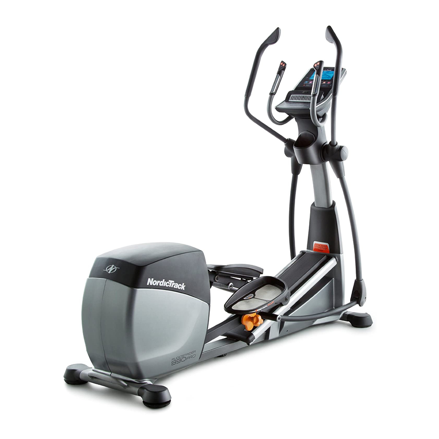
BEFORE YOU BEGIN Thank you for selecting the revolutionary reading this manual, please see the front cover of this NORDICTRACK AUDIOSTRIDER 990 PRO elliptical. manual. To help us assist you, note the product model ® The AUDIOSTRIDER 990 PRO elliptical provides an number and serial number before contacting us. -
Page 7: Part Identification Chart
PART IDENTIFICATION CHART Use the drawings below to identify the small parts needed for assembly. The number in parentheses below each drawing is the key number of the part, from the PART LIST near the end of this manual. The number following the key number is the quantity needed for assembly. -
Page 8: Assembly
ASSEMBLY • Assembly requires two persons. • In addition to the included tool(s), assembly requires the following tools: • Place all parts in a cleared area and remove the one Phillips screwdriver packing materials. Do not dispose of the packing materials until you finish all assembly steps. - Page 9 3. Identify the two Rear Stabilizer Tubes (2). While a second person lifts the rear of the Frame (1), insert some packaging materials (not shown) under the Frame. Have the second person hold the Frame to prevent it from tipping. Attach a Rear Stabilizer Tube (2) to the Frame (1) with three M10 x 20mm Screws (91) and three M10 Split Washers (105).
- Page 10 5. Tip: Avoid pinching the wires. Slide the Upright (4) onto the Frame (1). Attach the Upright (4) with eight M10 x 20mm Screws (91) and eight M10 Split Washers (105). Avoid pinching Do not tighten the Screws yet. the wires Slide the Upright Cover (81) downward.
- Page 11 7. Using a plastic bag to keep your fingers clean, apply some of the included grease to the Long Axle (35) and to two 16mm Wave Washers (54) (only one is shown). Insert the Long Axle (35) through the Upright (4) and center it.
- Page 12 9. Identify the Right Pedal (49) and orient it as shown. While a second person lifts the Right Pedal Plate (14), attach the Right Pedal (49) to the Right Pedal Plate with five M6 x 16mm Screws (103) and five M6 Washers (90). Tip: It may be help- ful to lift the right Pedal Arm (44).
- Page 13 11. Apply grease to a Short Axle (149) and to two M8 x 22mm Washers (97). Next, tighten an M8 x 16mm Screw (82) and an M8 x 22mm Washer (97) a few turns into the Short Axle (149). While a second person holds the front end of the Right Link Arm (59) inside the bracket on the Right Upper Body Leg (60), insert the Short Axle (149) through both parts.
- Page 14 13. Orient the Rear Console Cover (80) as shown. Attach the Rear Console Cover (80) to the Upright (4) with four M4 x 16mm Screws (101). 14. While a second person holds the Console (7) near the Upright (4), connect the wires on the Console to the Upper Wire (152) and to the Avoid pinching Right and Left Sensor Wires (108, 110).
- Page 15 15. Attach the Front Console Cover (79) around the Upright (4) by pressing the tabs on the Front Console Cover into the Rear Console Cover (80). 16. See step 6. Tighten the six M8 x 43mm Bolts (96). See step 5. Tighten the eight M10 x 20mm Screws (91).
-
Page 16: The Chest Heart Rate Monitor
THE CHEST HEART RATE MONITOR HOW TO PUT ON THE HEART RATE MONITOR • Do not expose the heart rate monitor to direct sun- light for extended periods of time; do not expose it to The heart rate temperatures above 122° F (50° C) or below 14° F monitor consists of (-10°... -
Page 17: How To Use The Elliptical
HOW TO USE THE ELLIPTICAL HOW TO PLUG IN THE POWER CORD HOW TO MOVE THE ELLIPTICAL This product must be grounded. If it should malfunc- Due to the size and weight of the elliptical, moving tion or break down, grounding provides a path of least it requires two persons. - Page 18 HOW TO ADJUST THE POSITIONS OF THE PEDALS HOW TO EXERCISE ON THE ELLIPTICAL Each pedal can To mount the elliptical, hold the upper body arms or the be adjusted to handlebars and step onto the pedal that is in the lowest several positions.
-
Page 19: Console Diagram/Features Of The Console
CONSOLE DIAGRAM FEATURES OF THE CONSOLE The advanced console offers an array of features designed to make your workouts more effective and enjoyable. When you use the manual mode of the console, you can change the resistance of the pedals and the incline of the ramp with the touch of a button. - Page 20 HOW TO TURN ON THE POWER HOW TO USE THE MANUAL MODE IMPORTANT: If the elliptical has been exposed to 1. Begin pedaling or press any button on the cold temperatures, allow it to warm to room tem- console to turn on the console. perature before turning on the power.
- Page 21 4. Follow your progress with the display. Stride—This display mode will show the total num- ber of strides you have pedaled. The display can show the following workout information: Time—When the manual mode is selected, this display mode will show the elapsed time. When a workout is selected, this display mode will show the time remaining in the workout.
- Page 22 When a wireless iFit When your pulse is detected, a heart symbol will module is connected, flash in the display each time your heart beats, one the wireless symbol at or two dashes will appear, and then your heart rate the top of the display will be shown.
- Page 23 HOW TO USE A PRESET WORKOUT resistance level, ramp incline level, and/or target rpm is programmed for the next segment, the resis- 1. Begin pedaling or press any button on the tance level, ramp incline level, and/or target rpm console to turn on the console. will appear in the display for a few seconds to alert you.
- Page 24 HOW TO USE AN IFIT WORKOUT 5. Select an iFit workout. You must have an iFit module to use an iFit workout. To select an iFit workout, press one of the iFit but- tons. Note: Before some workouts will download, To purchase an iFit module at any time, go to you must go to www.iFit.com and add them to your www.iFit.com or call the telephone number on the...
-
Page 25: To Use The Sound System
7. Follow your progress with the display. HOW TO CHANGE CONSOLE SETTINGS See step 4 on page 21. The console features a user mode that allows you to view usage information, select a unit of measurement, The My Trail tab will show a map of the trail you are and adjust the contrast level of the display. - Page 26 6. Select an audio setting for the voice of the Then, press the Enter button. After a few seconds, personal trainer if desired. the status of the iFit module will appear in the dis- play. To exit this display, press and hold down the Press the decrease button to view the audio setting Display button for a few seconds.
-
Page 27: Maintenance And Troubleshooting
MAINTENANCE AND TROUBLESHOOTING Inspect and tighten all parts of the elliptical regularly. HOW TO ADJUST THE REED SWITCH Replace any worn parts immediately. If the console does not display correct feedback, the To clean the elliptical, use a damp cloth and a small reed switch should be adjusted. - Page 28 Locate the Reed Switch (38). Loosen, but do not remove, the two M4 x 12.7mm Flange Screws (161). Next, rotate the Large Pulley (19) until a Magnet (43) is aligned with the Reed Switch (38). Slide the Reed Switch slightly toward or away from the Magnet. Then, retighten the M4 x 12.7mm Flange Screws (161).
-
Page 29: Exercise Guidelines
EXERCISE GUIDELINES Burning Fat—To burn fat effectively, you must exer- WARNING: cise at a low intensity level for a sustained period of Before beginning this time. During the first few minutes of exercise, your or any exercise program, consult your physi- body uses carbohydrate calories for energy. - Page 30 SUGGESTED STRETCHES The correct form for several basic stretches is shown at the right. Move slowly as you stretch; never bounce. 1. Toe Touch Stretch Stand with your knees bent slightly and slowly bend forward from your hips. Allow your back and shoulders to relax as you reach down toward your toes as far as possible.
-
Page 31: Part List
PART LIST Model No. 29835.1 R1212A Key No. Qty. Description Key No. Qty. Description Frame Pedal Arm Roller Rear Stabilizer Tube Ramp Arm Roller Ramp Ramp Arm Upright 16mm Wave Washer M4 x 19mm Screw Axle Cover Front Left Stabilizer Tube... - Page 32 Key No. Qty. Description Key No. Qty. Description M4 x 16mm Screw M10 x 45mm Bolt M8 Jam Nut M10 x 35mm Bolt M6 x 16mm Screw M10 Square Nut Power Switch Front Right Stabilizer Tube M10 Split Washer Right Track Shield Mount Right Ramp Cap M4 x 12mm TZP Screw...
-
Page 33: Exploded Drawing
EXPLODED DRAWING A Model No. 29835.1 R1212A... - Page 34 EXPLODED DRAWING B Model No. 29835.1 R1212A...
- Page 35 EXPLODED DRAWING C Model No. 29835.1 R1212A...
-
Page 36: Ordering Replacement Parts
ORDERING REPLACEMENT PARTS To order replacement parts, please see the front cover of this manual. To help us assist you, be prepared to provide the following information when contacting us: • the model number and serial number of the product (see the front cover of this manual) • the name of the product (see the front cover of this manual) • t he key number and description of the replacement part(s) (see the PART LIST and the EXPLODED DRAWING near the end of this manual) LIMITED WARRANTY IMPORTANT: To protect your fitness equipment with an extended service plan, see page 5.