Table of Contents
Advertisement
www.nordictrack.com
Model No. 23897.0
Serial No.
Write the serial number in the space
above for reference.
QUESTIONS?
If you have questions, or if parts
are damaged or missing, DO NOT
CONTACT THE STORE; please
contact Customer Care.
IMPORTANT: Please register this
product (see the limited warranty
on the back cover of this manual)
before contacting Customer Care.
CALL TOLL-FREE:
1-800-TO-BE-FIT
(1-800-862-3348)
Mon.-Fri. 6 a.m.-6 p.m. MT
Sat. 8 a.m.-4 p.m. MT
ON THE WEB:
www.nordictrackservice.com
USER'S MANUAL
__wlw_F
R E E
"_
/f_
HOW-TO
/
_rl
I_ k_)V,DEOS
/
.iFit.com
_'
Advertisement
Table of Contents

Related Manuals for NordicTrack E7.5 23897.0


Summary of Contents for NordicTrack E7.5 23897.0
- Page 1 Model No. 23897.0 USER'S MANUAL Serial No. Write the serial number in the space above for reference. QUESTIONS? If you have questions, or if parts are damaged or missing, DO NOT CONTACT THE STORE; please contact Customer Care. IMPORTANT: Please register this...
-
Page 2: Warning Decal Placement
325 Ibs / kgs. • This product should always be used on a level surface. • This product is not intended therapeutic use. • Replace label if damaged, illegible, NORDICTRACK is a registered trademark of ICON IP, Inc. -
Page 3: Important Precautions
IMPORTANT PRECAUTIONS WARNING: To reduce the risk of serious injury, read all important precautions and instructions in this manual and all warnings on your elliptical before using your elliptical. ICON assumes no responsibility for personal injury or property damage sustained by or through the use of this product. -
Page 4: Before You Begin
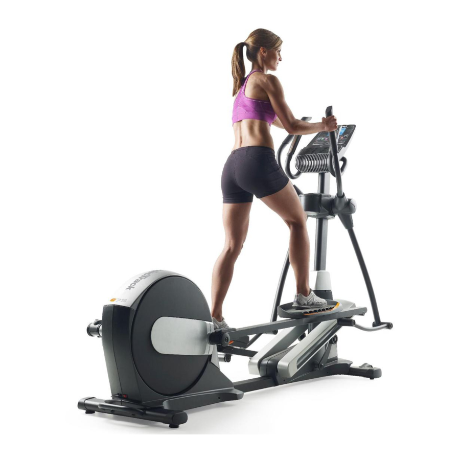
Thank you for selecting the revolutionary reading this manual, please see the front cover of this NORDICTRACK ®E 7.5 elliptical. The E 7.5 elliptical manual. To help us assist you, note the product model provides an impressive selection of features designed number and serial number before contacting us. -
Page 5: Part Identification
PART IDENTIFICATION CHART Use the drawings below to identify the small parts needed for assembly. The number in parentheses below each drawing is the key number of the part, from the PART LIST near the end of this manual. The number following the key number is the quantity needed for assembly. - Page 6 ASSEMBLY To watch an assembly • Left parts are marked "L" or "Left" and right parts video, go to are marked "R" or "Right." http://productvideo.co/ assembly/sears/nordic- • To identify small parts, see page 5. track or use your mobile phone or smartphone to •...
- Page 7 Orient the Front Stabilizer (3) as shown. While a second person lifts the front of the Frame (1), attach the Front Stabilizer (3) with two M10 x 120mm Screws (100). Identify and orient the Upright (5) and the Top Cover (23) as shown. Slide the Top Cover (23) upward onto the W ire Upright (5).
- Page 8 Identify the Right Upper Body Arm (8) and the Right Upper Body Leg (6) and orient them as shown. Insert the Right Upper Body Arm (8) into the Right Upper Body Leg (6). Attach the Right Upper Body Arm (8) with three M8 x 45mm Bolts (104) and three M8 Locknuts (105).
- Page 9 Note: The Leveling Foot (41) may be preattached. With the help of a second person, place some of the packaging materials (not shown) under the Frame (1). Have the second person hold the Frame to prevent it from tipping while you complete this step.
- Page 10 See the upper drawing. Locate the Ramp Roller (92) on the Right Pedal Arm (12). Set the Ramp Roller (92) on the right side of the Ramp (43). See the lower drawing. Pull upward on the Latch (117) on the Right Pedal Arm (12). Press the Right Pedal Arm (12) onto the right Sleeve (136).
- Page 11 10. Apply grease to a Link Arm Axle (94). Insert the Link Arm Axle (94) into the Right Upper Body Leg (6) and the Right Link Arm (90) from the side shown. Insert a hex key into the M8 x 25mm Screw (128) in the Link Arm Axle (94).
- Page 12 12. Orient the Rear Upright Cover (24) as shown. While a second person holds the Rear Upright Avoid pinching Cover (24) near the Upright (5), connect the the wires receiver wire (A) to the Receiver Extension Wire (143). Tip: Avoid pinching the wires.
- Page 13 15. Identify the Right Rear Leg Cover (29). Attach the Right Rear Leg Cover (29) around the Right Upper Body Arm (8) by pressing it into the Right Front Leg Cover (30). Repeat this step on the other side of the elliptical.
- Page 14 17. Have a second person hold the Handlebar (10) near the Upright (5). See the inset drawing. Locate the Pulse Wire (135) in the Handlebar (10). Insert the Pulse Wire into the front of the Upright (5) and pull it out of the hole in the Upright as shown.
- Page 15 19. While a second person holds the Console (33) near the Handlebar (10), connect the wires on the Console to the Upright Wire (60), to the Receiver Extension Wire (143), and to the Pulse Avoid pinching Wire (135). the wires Insert the excess wire into the Handlebar (10) or into the Console (33).
-
Page 16: How To Use The Elliptical
HOW TO USE THE ELLIPTICAL HOW TO PLUG IN THE POWER CORD A temporary adapter may Receptacle be used to This product must be grounded. If it should malfunc- connect the tion or break down, grounding provides a path of least Adapter resistance for electric current to reduce the risk of power cord... - Page 17 HOW TO FOLD AND UNFOLD THE ELLIPTICAL HOW TO MOVE THE ELLIPTICAL When the ellipti- To move the elliptical, first fold it as described at cal is not in use, the left. Next, stand in front of the elliptical, hold the the frame can upright, and place one foot against one of the wheels.
- Page 18 HOW TO EXERCISE ON THE ELLIPTICAL To dismount the elliptical, wait until the pedals come to a complete stop. Note: The elliptical does not have To mount the elliptical, hold the upper body arms and a free wheel; the pedals will continue to move until step onto the pedal that is in the lowest position.
-
Page 19: Console Diagram
CONSOLE DIAGRAM 17 -'!-.i7iJ I.L7iI /'.,J /f..J/ TIME DIST. INCLINE DISPLRM HOME ENTER iFIT COMPATIBLE TRAIN COMPETE TRACK A GOAL LOSE " ]I " ][ v^ CALORIe PERFORMANCE MRNURL CONTROL FEATURES OF THE CONSOLE through an optional iFit module. With the iFit mode, you can download personalized workouts, create your The advanced console offers an array of features own workouts, track your workout results, race against... -
Page 20: How To Turn On The Power
HOW TO TURN ON THE POWER Change the resistance of the pedals and the incline of the ramp as desired. IMPORTANT: If the elliptical has been exposed to cold temperatures, allow it to warm to room tem- As you pedal, change the resistance of the pedals perature before turning on the power. - Page 21 Incline--This display mode will show the incline As you exercise, the workout intensity level bar level of the ramp for a few seconds each time the will indicate the approximate intensity level of your exercise. incline level changes. Pulse--This display mode will show your heart rate when you use the handgrip heart rate monitor or an optional chest heart rate monitor (see step 5).
- Page 22 If there are Turn on the fan if desired. sheets of plastic Contacts on the metal The fan has low and contacts on the high speed settings. Press the fan increase handgrip heart and decrease buttons rate monitor, remove the repeatedly to select a fan speed or to turn off the fan.
- Page 23 HOW TO USE AN ONBOARD WORKOUT resistance level, ramp incline level, and/or target rpm is programmed for the next segment, the resis- Begin pedaling or press any button on the tance level, ramp incline level, and/or target rpm console to turn on the console. will appear in the display for a few seconds to alert you.
- Page 24 HOW TO USE A SET-A-GOAL WORKOUT Note: The calorie goal is an estimate of the number of calories that you will burn during the workout. The actual number of calories that Begin pedaling or press any button on the console to turn on the console. you burn will depend on various factors such as your weight.
- Page 25 HOW TO USE AN IFIT WORKOUT To compete in a race that you have previously scheduled, press the Compete button. You must have an iFit module to use an iFit workout. To re-run a recent iFit workout from your sched- To purchase an iFit module at any time, go to ule, first press the Track button.
- Page 26 Follow your progress with the display. HOW TO USE THE SOUND SYSTEM See step 4 on page 20. To play music or audio books through the console sound system while you exercise, plug your audio The My Trail tab will show a map of the trail you are cable into the jack on the console and into a jack on walking or running or it will show a track and the your MP3 player or CD player;...
- Page 27 HOW TO CHANGE CONSOLE SETTINGS If no module is connected, the display will show the words NO IFIT MODULE. If no module is con- The console features a user mode that allows you to nected, go to step 10. view usage information, select a unit of measurement, and adjust the contrast level of the display.
-
Page 28: Fcc Information
FCC INFORMATION This equipment has been tested and found to comply with the limits for a Class B digital device, pursuant to part 15 of the FCC Rules. These limits are designed to provide reasonable protection against harmful interference in a residential installation. This equipment generates, uses, and can radiate radio frequency energy and, if not installed and used in accordance with the instructions, may cause harmful interference to radio communications. -
Page 29: Maintenance
MAINTENANCE AND TROUBLESHOOTING HOW TO ADJUST THE REED SWITCH Inspect and tighten all parts of the elliptical regularly. Replace any worn parts immediately. If the console does not display correct feedback, the To clean the elliptical, use a damp cloth and a small reed switch should be adjusted. -
Page 30: How To Adjust The Drive Belt
HOW TO ADJUST THE DRIVE BELT See EXPLODED DRAWING B on page 37. Remove the M4 x 16mm Screws (93) and the M4 x 42mm If you can feel the pedals slip while you are pedaling, Screws (124) from the Right and Left Shields (18, 19). Make sure to note which size Screws come from even when the resistance is adjusted to the highest level, the drive belt may need to be adjusted. -
Page 31: Exercise Guidelines
EXERCISE GUIDELINES Burning Fat--To burn fat effectively, you must exer- cise at a low intensity level for a sustained period of time. During the first few minutes of exercise, your body uses carbohydrate calories for energy. Only after the first few minutes of exercise does your body begin to use stored fat calories for energy. -
Page 32: Suggested Stretches
SUGGESTED STRETCHES The correct form for several basic stretches is shown at the right. Move slowly as you stretch; never bounce. 1. Toe Touch Stretch Stand with your knees bent slightly and slowly bend forward from your hips. Allow your back and shoulders to relax as you reach down toward your toes as far as possible. - Page 33 NOTES...
-
Page 34: Part List
PART LIST Model No. 23897.0 R0812A Key No. Qty. Description Key No. Qty. Description Frame Left Lift Arm Folding Frame Lift Axle Bushing Front Stabilizer Long Motor Axle Rear Stabilizer Short Motor Axle Upright Bumper Right Upper Body Leg #8 x 25mm Self-tapping Screw Left Upper Body Leg Upright Bushing M10 x 60mm Bolt... - Page 35 Key No. Qty. Description Key No. Qty. Description Anchored Zip Tie M8 x 30mm Screw M8 x 16mm Screw M8 x 25mm Screw M10 Locknut Outer Sleeve Bushing M8 x 45mm Bolt Small Snap Ring M8 Locknut M8 Split Washer Link Arm Bushing Short Spring Pin M10 x 25mm Screw...
- Page 36 I"11 "IB I"11 6") 1",3 "4 1",3...
- Page 37 I"11 I"11 93 77 '"4 t..O "4 3>...
- Page 38 58 ._(_ 110 102...
- Page 39 "i €0 1",5 "4 1",5...
-
Page 40: Ordering Replacement
ORDERING REPLACEMENT PARTS To order replacement parts, please see the front cover of this manual. To help us assist you, be prepared to provide the following information when contacting us: • the model number and serial number of the product (see the front cover of this manual) •...