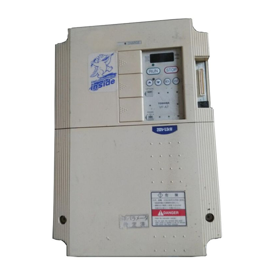
Toshiba TOSVERT VF-A7 Instruction Manual
The new generation high-performance inverter 200v class 0.4- 90kw 400v class 0.75-280kw
Hide thumbs
Also See for TOSVERT VF-A7:
- Instruction manual (50 pages) ,
- Manual (14 pages) ,
- Function manual (5 pages)
Table of Contents
Advertisement
Quick Links
Instruction Manual
The new generation
high-performance inverter
TOSVERT
200V class 0.4
400V class 0.75 280kW
1. Make sure that this instruction manual is delivered to the end user of
the inverter unit.
2. Read this manual before installing or operating the inverter unit, and
store it in a safe place for reference.
© TOSHIBA Schneider Inverter Corporation 2001
All Rights Reserved.
A7
TM
VF-
90kW
NOTICE
Safety
I
precautions
II
Preface
Contents
1
2
3
4
5
6
Operation
7
with external
signal
Monitoring
8
operation
status
Peripheral
9
units
Table of
10
11
Specification
Prior to
12
service call
Regular
13
inspection and
maintenance
14
Warranty
Precautions
15
of disposal
Advertisement
Chapters
Table of Contents

Related Manuals for Toshiba TOSVERT VF-A7


Summary of Contents for Toshiba TOSVERT VF-A7
-
Page 1: Table Of Contents
Regular the inverter unit. inspection and 2. Read this manual before installing or operating the inverter unit, and maintenance store it in a safe place for reference. Warranty © TOSHIBA Schneider Inverter Corporation 2001 All Rights Reserved. Precautions of disposal... -
Page 2: Safety Precautions
Safety precautions The labels on the inverter and this instruction manual contain important instructions for the prevention of possible injury to the user and other persons and damage to property, as well as for the safe use of the inverter. Please gain a good understanding of the following pictorial symbols before reading this manual and strictly observe the instructions that follow each symbols. - Page 3 Handling in general Danger Reference Never disassemble, modify or repair the inverter. Its disassembly could cause an electric shock, afire or an injury. Request your TOSHIBA dealer for repair. Never Disassemble -Never open the front cover of the inverter(or the door of the cabinet in which the inverter is installed) when the inverter is energized, or you could get a shock since a high voltage is applied to certain portions of it.
- Page 4 -Do not install or operate the inverter if it is damaged or any part is missing from it. Operating the inverter in a defective condition could lead to a shock or a fire. Request your Toshiba dealer for repair. -Do not put any inflammable material near the inverter, or it could catch a 1.4.4...
- Page 5 Wiring Danger Reference -Do not connect the power cable to any output terminal (U/T1, V/T2 or W/T3 on the motor side), or the inverter could break down and cause a fire. -Do not connect a resistor to any D.C. terminal (between PA and PC or PO and PC), or the inverter could cause a fire.
- Page 6 About operation Danger Reference -Do not touch any inverter's terminal when it is energized even if the motor is standstill, or you could get a shock. -Do not operate switches with a wet hand or not put a wet cloth on the inverter, or you could get a shock.
- Page 7 -Do not replace any part yourself, or you could get a shock or an injury, or 13.2 cause a fire. Request your Toshiba dealer for replacement of parts. Prohibited -Carry out inspection and maintenance on a daily basis. Failure to do so to find defects in the inverter could lead to accidents.
-
Page 8: Preface
Preface Thank you for purchasing the industrial inverter "TOSVERT VF-A7". This inverter has a "Ver. 312"CPU or later. Please refer to "10. Table of parameters" for the functions available for the inverter with a CPU in this version. The CPU version will be frequently upgraded. - Page 9 Contents sheet Safety precautions Preface Contents sheet Read this section first Checking the purchase Contents of the product code Names and functions Panel description Main circuit, control power supply and control circuit terminal boards Detaching the terminal board front cover Notes on the application of inverters Notes on motors combined with inverters A-11...
- Page 10 Explanation of the basic parameters Setting the acceleration and deceleration times Automatic acceleration/deceleration Manually setting the acceleration and deceleration times Increasing starting torque/ energy-saving operation mode Selecting an operation mode E-10 Setting and calibrating meters E-13 Factory default setting E-15 Forward/reverse run selection (for the panel control only) E-15 Maximum frequency...
- Page 11 F-18 Jog run F-19 Jump frequency - Jumping resonant frequencies F-19 Preset-speed #8 15 F-20 PWM carrier frequency F-20 Trip-less enhancement F-20 Auto-restart (restart during free-run (coast)) F-23 Regenerative power ride-through control / Deceleration stop F-24 Retry function F-25 Dynamic (regenerative) braking - To urgently stop the motor F-29 Avoiding over-voltage trip F-29...
- Page 12 F-65 Meter output F-65 Setting of meter outputs F-65 Setting of optional meter outputs F-65 Pulse output to meters F-66 Control panel parameters F-66 Prohibiting the change of parameter settings F-66 Changing the units of display F-67 Display the motor speed and the load speed F-67 Column number below decimal point of Frequency, Acc/dec time F-68...
- Page 13 Table of parameters Specifications by types Standard specifications by types External dimensions and mass Prior to service call Trip information and counter measures Cause of trip, warning indication (in detail and countermeasures) Method of resetting causes of trip In the case motor does not run in spite of no trip message appearing ... How to check other troubles Regular inspection and maintenance Regular inspection...
-
Page 14: Read This Section First
Read this section first 1.1 Checking the purchase Make sure that the inverter delivered is exactly what you ordered. Warning Use an inverter which matches the input power rating of your three-phase induction motor. The use of an inverter unsuitable for your motor can cause it to rotate in a wrong direction, and thus lead to grave accidents, including its burning due to overheating. -
Page 15: Names And Functions
1.3 Names and functions 1.3.1 Panel description VEC lamp RUN lamp MON lamp PRG lamp Lit when the inverter is in Lit when the inverter Lit when the Inverter Lit when the operation or blinks when It is in parameter is in vector control inverter is in is in auto acceleration/... - Page 16 Warning label on the top (*1) Cooling fin Connectors for optional add-on module/board Wiring hole (*2) Ventilation slits Rating label [Bottom view] [Side view] (*1) Peel off this label when the inverter is installed in a rather hot place. (Models for 15kW motor or smaller) (*2) Using scissors or a cutter, cut the rubber bush in the wiring hole as shown below.(Models for 22kW motor or smaller) Rubber bush...
-
Page 17: Main Circuit, Control Power Supply And Control Circuit Terminal Boards
1.3.2 Main circuit, control power supply and control circuit terminal boards Main circuit terminal board VFA7-2004PL 2037PL VFA7-4007PL 4037PL VFA7-2055PL, 2075PL VFA7-4055PL, 4075PL VFA7-2110P 2150P VFA7-4110PL 4150PL... - Page 18 VFA7-2185P, 2220P VFA7-4185P, 4220P Grounding terminal VFA7-2300P, 4300P VFA7-4370P1 4550P1...
- Page 19 VFA7-2370P1 2550P1 VFA7-4750P1 VFA7-2750P1 VFA7-4110KP1, 4132KP1 VFA7-2900P1 VFA7-4160KP1 4280KP1...
- Page 20 Control power supply terminal board Note)To use R0,S0 terminal on 22kW model or smaller, you need a Control power supply unit option.(Refer to 9.4) VFA7-2055PL 2220P VFA7-2300P VFA7-4055PL 4220P VFA7-4300P VFA7-2370P1 2900P1 VFA7-4370P1 4280KP1 Control power supply inputs Control power Power supply supply inputs(*1) for control circuit (*1)Refer to 2.2 for the connection of control power...
-
Page 21: Detaching The Terminal Board
Control circuit terminal The control circuit terminal board is common to all models. Screw size M3 ST-CC shorting bar Refer to section 2.3.2 for the functions of terminals. 1.3.3 Detaching the terminal board front cover Detach the front lower cover for wiring, following the steps below. Less than 22kW Hooked Remove the two screws... -
Page 22: Notes On The Application Of Inverters
So, reduce the motor's output below the rated load when operating it in a low speed range. If you wish to operate a motor continuously at the rated torque, then use a Toshiba VF motor designed specially for use in conjunction with an inverter. When the inverter is combined with a VF motor, its overload protection level needs to be changed to "VF motor"... - Page 23 In circuit configuration 2, the brake is turned on and off by means of a low-speed signal OUT1. However, for certain applications, e.g., elevator applications, it is recommended to use a low-speed detection signal (function of terminal OUT1) to turn on and off the motor. Contact your Toshiba dealer before designing a system. A-10...
-
Page 24: Notes On Inverters
1.4.2 Notes on inverters Over-current protective function The inverter has an over-current protective function. The current for this protection is adjusted to the maximum current rating of the applicable motors by default. Therefore, when the inverter is used to control a motor with a relatively small capacity, it is necessary to readjust the over-current protection level and the electronic thermal protective function. -
Page 25: Influences Of Leakage Currents And Measures Against It
Use parameter to lower the PWM carrier frequency. 2. Use high frequency-ready ground leakage breakers (e.g., Esper Mighty series(manufactured by Toshiba Schneider Electric Ltd.)). When these ground leakage breakers are installed, there is no need to lower the PWM carrier frequency. - Page 26 Power Inverter supply Measures to be taken: 1. Use the electronic thermal function provided for the inverter. Use parameter , to set the electronic thermal function. 2. Lower the PWM carrier frequency, though this results in an increase in motor magnetic noise. Use parameter ...
-
Page 27: Installation Environment
Prohibited If you intend to install the inverter where a chemical or solvent other than those listed below is used, consult your Toshiba dealer in advance. (Table1) (Table 2) - Page 28 In such a case, contact your Toshiba dealer in advance. If installing the inverter close to any of the following appliances or devices, take necessary measures to prevent them from malfunctioning.
-
Page 29: Installation Place
Failure to do so could lead to injury to persons since it has no emergency stop function. - Do not use any optional devices other than those designated by Toshiba. The use of improper devices could lead to accidents. - Page 30 Calorific values of inverters and amount of air to be ventilated The VF-A7 series of inverter loses about 5% of energy when switching electric currents from AC, DC, then to AC. To limit a temperature rise due to this energy loss, it is necessary to forcefully ventilate and cool down the cabinet in which the inverter is installed.
- Page 31 Control panel designed in consideration of possible influences of noise Inverters produce high-frequency noise. To avoid influences of noise, measures must be taken in designing a control panel. Here are some examples of measures against noise. Separately install the wires of the main circuit and those of the control circuit. Do not install their wires in the same duct or in parallel with each other, and do not bind them together.
- Page 32 Heat-sink going out attachment(simple type) To install a standard VF-A7 designed for 37kW motor or larger, you can choose a one from next two forms. (1) Normal attachment (Whole the inverter is in the cabinet) (2) Heat-sink going out (the cabinet) attachment(simple type) Heat-sink going out attachment reduces the generation of heat inside the cabinet.
-
Page 33: Connection
Danger Never disassemble, modify or repair the inverter. Its disassembly could cause an electric shock, a fire or an injury. Request your Toshiba dealer for repair. Disassemble Do not put or insert anything (e.g., an electric cable, a bar or a steel wire) into the inverter, or the inverter could cause a shock or a fire. - Page 34 Warning Do not connect any device or unit with a built-in capacitor (noise filter, surge suppressor, etc.) to output terminals (on the motor side), or it could cause the risk of a fire. Prohibited Prevention of radio noise Prevent interference, such as radio noise, separately install and bind cables connected to the power supply-side terminals (R/L1, S/L2 and T/L3) of the main circuit and those connected to the motor-side terminals (U/T1, V/T2 and W/T3).
-
Page 35: Standard Connection
2.2 Standard connection Danger -Do not connect the power cables to any output terminal (U/T1, V/T2 or W/T3 on the motor side), or the inverter could break down and cause a fire. -Do not connect a resistor to any D.C. terminal (between PA and PC or PO and PC), or Prohibited the inverter could cause a fire. - Page 36 [Standard connection diagram for sink logic(minus common)] 200V class: 30 55kW 400V class: 30 75kW When the built-in dynamic braking circuit DC reactor (DCL) Braking unit (GTR7) is modified to *2 (Optional) connect an external (Optional) Main circuit power supply dynamic braking resistor 200V class 30 55kW 3-phase 200 220V-50Hz...
- Page 37 [Standard connection diagram for sink logic(minus common)] 200V class: 75 90kW 400V class: 110 280kW Be sure to attach DC reactor. Dynamic braking resistor DC reactor (DCL) (Optional) *2 (Optional) Main circuit power supply 200V class 75,90kW 3-phase 200 230V-50Hz/60Hz 400V class 110 280kW 3-phese 380 460V-50Hz/60Hz Motor...
-
Page 38: Explanation Of Terminals
2.3 Explanation of terminals 2.3.1 Main circuit terminals Figure below shows an example of the wiring of the main circuit. Use optional devices, as required. Connecting a power source and a motor VF-A7 Connect the power Connect the motor Power source source to the terminals cables to the terminals R, S and T. - Page 39 Terminal symbol Function A negative potential terminal of the internal dc main circuit. This terminal can be used to connect a dc common power source in conjunction with the terminal PA (positive potential). Used to connect a DC reactor (DCL: external option). The inverter is shipped with these PO, PA terminals shorted.
-
Page 40: Control Circuit Terminals (Sink Logic(Minus Common
2.3.2 Control circuit terminals (sink logic(minus common)) ST-CC shorting bar Electrical Inverter internal Terminal Input / Function specification circuit symbol output The motor rotates in forward direction if F and CC are connected, while it slows down to a stop No-voltage Input if this Connection is broken. - Page 41 Input / Electrical Inverter internal Terminal Function output specification circuit symbol Multifunction programmable analog output. Factory 1mA full-scale dc default setting: Operation frequency command. ammeter Output Connect 1mAdc full-scale ammeter 7.5Vdc-1mA full- 7.5Vdc(10Vdc)-1mA full-scale voltmeter. scale dc voltmeter Multifunction programmable analog output. Factory 1mA full-scale dc default setting: Output current.
- Page 42 Sink logic (minus common)/source logic (plus common) ... Switching I/O terminal The input terminals of most control circuits are designed so that they turn on when a current flows out. This type of logic is referred to as the "sink logic" (default setting). In Europe, however, the "source logic"...
-
Page 43: Serial Rs485 Communication Connector
2.3.3 Serial RS485 communication connector Figure of serial RS485 communication connector To use the serial RS485 connector, detach the cover for serial RS485 connector. Pin-8 Pin-1 Signal name Pin number content Same phase reception data(positive line) Anti-phase reception data(positive line) Same phase transmitting data(positive line) Anti-phase transmitting data(positive line) Ground line of signal data... -
Page 44: Operating The Inverter
Failure to do so could lead to a fire. If any defect is found, Mandatory request your Toshiba dealer for repair. Turn off the power before leaving the inverter out of operation for a long period of time. -
Page 45: Control Modes Of The Vf-A7 Inverter
3.1 Control modes of the VF-A7 inverter [Speed control mode] : The motor runs at the speed specified by a frequency command. (1) V/f control - V/f constant (constant torque characteristic) ... [default setting] For loads, such as belt conveyors and cranes, that require, even in low speed ranges, the same torque as that produced at their respective rated speeds. -
Page 46: Simple Operation Of The Vf-A7 [1] [Speed Control Mode
3.2 Simple operation of the VF-A7 [1] [Speed control mode] A speed control mode can be selected from among three: control panel operation, terminal board operation and combination of both. (Refer to 5.3 for other modes of operation.) [Terminal operation] : Operation by means of external signals [Panel operation] : Operation by means of keys on the control panel... -
Page 47: Frequency Setting
Frequency setting Setting the operation frequency with an external volume control By default, the VF-A7 inverter has been set to a mode in which an external volume control can be used for setting the operation frequency. Volume control The operation frequency by potentiometer (1 to 1/4 W) for setting Refer to 7.3 for details of adjustment. - Page 48 Setting the frequency by voltage signals (0 to 10 Vdc) Voltage signal Voltage signals (0 to 10 V) for setting the operation frequency Refer to 7.3 for details of Voltage signals 0-10Vdc adjustment. 80Hz Frequency 10Vdc 0Vdc [Parameter setting] Necessary to change the VI/II input point 1 setting Speed setting mode selection parameter ...
- Page 49 3.2.2 Operation from the control panel Control panel operation This section describes how to start/stop the motor, and set the operation frequency with the operating panel. Ex. of typical connection Set the operation freq. Motor MCCB Start the motor U/T1 R/L1 Power S/L2...
- Page 50 Example of control panel operation Key operated LED display Operation Display the running frequency. (If the monitor display selection parameter is set at [Running frequency]) Set the operation frequency. Save the operation frequency by pressing Enter key. ...
- Page 51 3. 3 Simple operation of the VF-A7 [2] [Torque control mode] An operation mode can be selected from among three: control panel operation, terminal board operation and combination of both. [Terminal operation] : Operation by means of external signals [Operating panel operation] : Operation by pressing keys on the control panel [Operating panel+terminal operation] : Frequency, start/stop signals can be sent individually...
- Page 52 Step 2: Switching from speed control mode to torque control mode, using external terminals, and assigning the control mode switching function to the terminal S4. S4: Control mode S4: Control mode switching switching S4-CC disconnected: Speed control S4-CC connected: Torque control Control mode Speed control Control mode...
-
Page 53: Polarity Of Torque Command
3.3.2 Polarity of torque command When using the torque limit function in torque control mode or speed control mode, change the polarity of the torque command, as required. Title Function Title Adjustment range Default setting Torque reference : Fixed direction ... -
Page 54: Torque Command
3.3.3 Operation from the terminal(external signal) [Torque control mode] Start/stop If this connection or disconnection has no effect, are connected : Forward run check the following parameter. (Operation command mode are disconnected : Free-run stop selection) (When terminals are electrically connected) [Example of typical connection] Motor... - Page 55 2) Torque setting by means of current signals (4 to 20 mAdc) Current signal Torque command by means of current signals (4 to 20 mAdc) 100% Current signals 4 20 mAdc Motor torque 20mAdc 4mAdc Set the torque reference selection (VI/II input).) 3) Torque setting by means of voltage signals (0~10 Vdc) Voltage signal...
- Page 56 5) Others : RX2 : Control panel parameter(Refer to 3.3.4 for details.) : Binary/BCD input : Communication common serial option : Communication RS485(Refer to 6.3.2 for details.) : Communication add-on option [Setting procedure: Setting the parameter at for current signal(4 to 20mAdc)] Key operated LED display Operation...
-
Page 57: Operation From The Control Panel
3.3.4 Operation from the control panel [Torque control mode] This section describes how to set the start and stop control modes, as well as torque commands from the control panel. Setting the start and stop modes To make it possible to start/stop from the operating panel in torque control mode, [Set the basic parameter (operation command mode selection) at (operating panel).] [Setting procedure]... - Page 58 Example of control panel operation 1. Set the torque command. Follow the steps described in the Example of typical connection table below to set the torque Motor command (). U/T1 R/L1 S/L2 V/T2 T/L3 W/T3 Starts the motor Stops the motor Operating panel Note)Pressing the Stop key causes the ON: Torque control...
-
Page 59: Basic Operation
[Speed control mode] 4. Basic operation of the VF-A7 [Torque control mode] The VF-A7 inverter has the following three display modes: [Normal monitor mode] Normal display mode. The inverter automatically enters this display mode when it is turned on. This mode enables you to monitor the output frequency and set frequency command values. - Page 60 About the parameter's adjustment range : A value larger than the upper-limit value is entered or the value set for the currently-selected parameter becomes larger than the upper-limit value because another parameter was changed. : A value smaller than the lower-limit value is entered or the value set for the currently-selected parameter becomes smaller than the lower-limit value because another parameter was changed.
- Page 61 [Basic parameter list] Default Reference Title Function Adjustment range setting section Automatic : Manual acceleration/deceleration 5.1.1 acceleration/deceleration : Automatic acceleration/deceleration : (0 is always displayed.) : Automatic torque boost + auto-tuning Automatic V/f mode setting : Sensorless vector control (speed) + auto-tuning : Automatic energy-saving + auto-tuning : Terminal block enabled : Operating panel enabled...
-
Page 62: How To Set Extended Parameters
4.1.2 How to set extended parameters The VF-A7 inverter has extended parameters to allow you to make full use of its functions. The code of every extended parameter is composed up of an and a 3-digit number. Extended parameter ... -
Page 63: Searching For Changed Parameters And Changing Their Settings Again
Example of parameter setting Follow the procedure below to set a parameter. (Example of setting: Changing the positive torque limit parameter from 150 to 100) Key operated LED display Operation The operation frequency is displayed. (Make this setting when the motor is out of operation.)(If the monitor ... - Page 64 Searching for a parameter and changing its setting Follow the procedure below to search for parameters and change their settings. Key operated LED display Operation The operation frequency is displayed. (Make this setting when the motor is out of operation.)(If the monitor display ...
-
Page 65: Parameters That Cannot Be Changed During Operation
4.1.4 Parameters that cannot be changed during operation For safety, the following parameters are designed so that they cannot be changed when the inverter is in operation. So, you need to stop the motor in advance to change these parameters. [Basic parameters] ... - Page 66 Following parameters are designed considering maintenance that they cannot be reset to the factory default setting even if you set the parameter at (see 5.5). Moreover, x-marked (see 4.1.3) parameters are not displayed on the user parameter group even if their settings are different from their default settings.
-
Page 67: Explanation Of The Basic Parameters
5. Explanation of the basic parameters Basic parameters refer to parameters you need to set before the first use after purchase. 5.1 Setting the acceleration and deceleration times Automatic acceleration/deceleration Acceleration time #1 Deceleration time #1 Function 1)The acceleration time parameter ... -
Page 68: Manually Setting The Acceleration And Deceleration Times
If you set in advance the acceleration and deceleration times (,) so that they match the average load condition, you can make the optimum setting to control the motor with a higher accuracy according to changes in the load applied. [Procedure for setting the automatic acceleration and deceleration times] Key operated LED display... -
Page 69: Increasing Starting Torque/ Energy-Saving Operation Mode
5.2 Increasing starting torque/ energy-saving operation mode Automatic V/f mode setting Function This parameter enables the inverter to automatically switch V/f control modes and set the motor constant (online automatic control) at the same time to make the motor produce larger torque. - Page 70 The vector control (Increasing the starting torque and operating with a higher accuracy) Set the automatic V/f mode setting at (vector control (speed) and auto-tuning). By setting the automatic V/f mode setting at (vector control (speed control) and auto- tuning), the motor reach its full potential and produce large torque even at low speeds.
- Page 71 (Automatic V/f mode setting) and (Motor control mode selection) The automatic control parameter is designed to set motor control mode selection parameter () and the auto-tuning parameter() by one operation. Therefore, changing the setting causes the settings of all related parameters to be changed automatically. Parameters set automatically ...
-
Page 72: Selecting An Operation Mode
5.3 Selecting an operation mode : Operation command mode selection : Speed setting mode selection Function These parameters are to select the operation command from among the operating panel, the terminal board, a communication device and other optional control devices, to which priority should be given when start, stop or frequency reference are issued by them. - Page 73 [Set value] : VI/II input Speed commands are entered by means of external signals (terminal VI: 0 to 10 Vdc or terminal II: 4 to 20 mAdc). : RR input Speeds commands are entered by means of external signals (terminal RR: 0 to 10Vdc). : RX input Speed commands are entered by means of external signals (terminal RX: 0 to +/-10 Vdc (+/-5 Vdc).
- Page 74 1) Setting the start, stop and operation frequencies with the operating panel Title Function Set value [Start/stop]: Press the key on the control STOP panel. Operation command (operating panel) Mode selection To switch between forward run and reverse run, use Speed setting mode the forward/reverse run selection parameter .
- Page 75 3) Start and stop (forward run, reverse run, free-run stop) with the operating panel and to set the operation frequency by external signals [Start/stop]: Press the key on the STOP Title Function Set value operating panel. Operation command (operating panel) To switch between forward run and reverse run, mode selection use the forward/reverse run selection .
-
Page 76: Setting And Calibrating Meters
5.4 Setting and calibrating meters FM Terminal meter selection FM Terminal meter adjustment AM Terminal meter selection AM Terminal meter adjustment Function The terminals AM and FM send out analog voltage signals. Absolute value output Use a full-scale 0~1 mAdc ammeter or a full-scale 0~7.5 Vdc (10 Vdc) voltmeter. To calibrate the meter connected to the terminal FM or AM, use the FM Terminal meter adjustment ... - Page 77 [Terminal AM-related parameters] Title Function Adjustment range Default setting Same as (: disabled) AM Terminal meter selection AM Terminal meter adjustment Resolution Both the terminals FM and AM have a maximum resolution of 1/1024. With the default settings, FM terminal outputs about 16 V (external impedance is infinity) or about 3mA (external impedance is 0 ohm), when running frequency is 80Hz.
- Page 78 [Example: Procedure of calibrating the meter connected to the terminal AM to which "output current" is assigned.] Key operated, LED display Operation The running frequency is displayed.(If the monitor display mode setting parameter is set at . [Running frequency]) Press the MON key to call up the first basic parameter ...
-
Page 79: Factory Default Setting
5.5 Factory default setting Standard setting mode selection Function This parameter is to set two or more parameters at a time for different commands. Using this parameter, all parameters can be also return to their respective default settings by one operation, and save or set specific parameters individually. - Page 80 [ Factory default setting ( = ) ] Setting at returns all parameters to their respective default settings. When this parameter is set at 3, is displayed for a while, then switches back to the original display ( ...
-
Page 81: Forward/Reverse Run Selection (For The Panel Control Only)
5.6 Forward/reverse run selection (for the panel control only) Forward/reverse selection Function This parameter is used to set the direction of a motor when it is started or stopped by pressing the Run key or Stop key on the control panel. This parameter is valid only when the operation command mode selection parameter ... -
Page 82: Upper And Lower Limit Frequencies
5.8 Upper and lower limit frequencies Upper limit frequency Lower limit frequency Function These parameters are used to set the upper and lower limit frequencies which are the largest and smallest frequencies, respectively, that the inverter can output. Upper limit frequency Lower limit frequency Output frequency [Hz]... -
Page 83: Control Mode Selection
5.10 Control mode selection Motor control mode selection Function The VF-A7 has the following V/f control modes: Constant torque characteristic Variable torque mode Automatic torque boost *1 Sensorless vector control (speed) *1 Automatic torque boost + automatic energy-saving Sensorless vector control + automatic energy-saving *1 V/f 5-point setting Sensorless vector control (torque/speed switching) PG feedback vector control (torque/speed switching) - Page 84 Basically, however, there is no need to set the motor constant if the inverter is used for a Toshiba 4P motor with the same capacity as the inverter. The motor constant can be set in any of the following three ways: Set the basic parameter ...
- Page 85 Basically, however, there is no need to set the motor constant if the inverter is used for a Toshiba 4P motor with the same capacity as the inverter. The motor constant can be set in any of the following three ways: 1)Set the basic parameter ...
- Page 86 [Set the motor control mode selection parameter at (Sensor-less vector control + automatic energy-saving).] In vector control mode, the VF-A7 inverter enables the Toshiba standard motor combined with it to produce large torque even at extremely low speeds. In addition, the output current is optimally adjusted for energy saving according to the load applied.
- Page 87 Basically, however, there is no need to set the motor constant if the inverter is used for a Toshiba 4P motor with the same capacity as the inverter. The motor constant can be set in any of the following two ways: 1) Set the extended parameter ...
-
Page 88: Switching Between Speed Control And Torque Control
5.11 Switching between speed control and torque control Motor control mode selection Input terminal selection #1 to #8 (One of these functions(terminals) is used.) Function These parameters are used to switch between speed control and torque control by external operation (signal input to a terminal) or by communication. -
Page 89: Torque Reference
[Torque reference] The command set with the parameter is valid. (Default setting: RX input) Title Function Adjustment range Default setting : VI (voltage input)/II (current input) : RR (volume/voltage input) : RX (voltage input) : RX2 (voltage input) (optional) ... -
Page 90: Setting The Electronic Thermal Protective Function
5.12 Manual torque boost - Increasing the torque produced at low speeds Manual torque boost Function When the torque produced in low speed ranges is not large enough, it can be boosted up by increasing the torque boost rate with this parameter. Base-frequency voltage ... - Page 91 1) Setting the electronic thermal protection characteristics parameter the motor overload protection level #1 The electronic thermal protection characteristics selection parameter is used to enable or disable the motor overload trip function () and the soft stall function. The motor overload trip function () needs to be selected with the parameter , while the inverter overload trip function () is always activated.
- Page 92 [Example of setting: VF-A7 2007PL with a 0.4 kW motor (rated current: 2A)] Key operated LED display Operation The running frequency is displayed. (Make this setting when the motor is out of operation.)(If the monitor display mode setting parameter is set at [Running frequency]) Press the MON key to call up the first basic parameter ...
- Page 93 2) Motor 150%-overload time limit The motor 150%-overload time limit parameter is used to set the time elapsed before the motor trips under a load of 150% (overload trip ) within a range of 10 to 2400 seconds. ...
-
Page 94: Preset-Speed Operation (15 Speeds)
5.14 Preset-speed operation (15 speeds) Preset-speed #1 to #7 Preset-speed #8 to #15 Preset-speed #1 to #15 control mode Function These parameters allow you to set up to 15 operating speeds just by switching contact signals externally. - Page 95 [An example of the connection of terminals ] Forward run command) F (Forward run) R (Reverse run) Reverse run command) Preset-speed #1 Preset-speed #2 Preset-speed #3 Preset-speed #4 3) Use of a preset-speed command in combination with another speed command When no preset-speed command is issued, the inverter accepts an input command from the control panel or another analog input device.
- Page 96 4) Setting the operation mode An operation mode can be selected for each preset-speed. Operation mode setting Title Function Adjustment range Default setting Present-speed operation : Disabled mode : Enabled : Disabled ... Only frequency commands are governed by the preset-speed command (#1 to #15) entered.
-
Page 97: Extended Parameters
6. Extended parameters Speed control mode Torque control mode Extended parameters are used for sophisticated operation, fine adjustment and special purposes. Change parameter settings, as required. Extended parameter list => Refer to Chapter 10. 6.1 Frequency signals 6.1.1 Low-speed signal ... -
Page 98: Putting Out Signals Of Arbitrary Frequencies
6.1.2 Putting out signals of arbitrary frequencies Speed reach setting frequency Speed reach detection band Function When the output frequency enters the frequency range delimited by the frequencies set arbitrarily with the parameters and ( (-set frequency) +/- (-set frequency) ), an ON or OFF signal is put out. -
Page 99: Selection Of Input Signals
6.2 Selection of input signals 6.2.1 Changing standby signal function ST (standby) signal selection Function This parameter is used to set the function of the standby signal (ST). 1) Normal setting (Standby if ST and CC are connected (ON), gate OFF if they are disconnected (OFF) (coast stop) 2) Always ON 3) Interlocked with F/R (Forward/reverse run if F/R and CC are connected, coast stop if they are... -
Page 100: Assigning Priority To The Terminal Board In Panel Operation Mode
[=(reverse)] The motor runs in reverse direction if F-CC and R-CC are closed simultaneously. Output frequency [Hz] Forward Reference frequency Reference frequency Reverse F-CC R-CC The motor slows down to a stop if F-CC and R-CC are [=(Stop)] closed simultaneously. Output frequency[Hz] Forward Reference frequency... - Page 101 [: terminal board has priority (Enabled)] Priority is given to commands entered from the terminal board even in control panel operation mode. Command from the control panel Internal command (=) Command from the terminal board A: No command from the terminal board. A: Command from the terminal board.
-
Page 102: Binary/Bcd Signal Selection(Expansion Tb Option Unit)
[When terminalsS3, S4 and CC are assigned to forced jog forward/reverse] Assign the control terminal S4 (default: 16 (preset-speed # 4)) to jog run. Title Function Adjustment range Setting value Input terminal selection #7(S3) (Forced JOG forward rotation) ... -
Page 103: Selection Of Terminal Functions
6.3 Selection of terminal functions 6.3.1 Keeping an input terminal function always active (ON) Always active function selection Function This parameter is used to select a function to be kept always active (ON) from among the input terminal functions. (One function can be selected) Parameter setting Title Function... -
Page 104: Changing Output Terminal Functions
6.3.4 Changing output terminal functions Output terminal selection #1 (OUT1) Output terminal selection #2 (OUT2) Output terminal selection #3 (FL) Output terminal selection #4 #7 Refer to 7.2.2 for details. 6.3.5 Response times of input/output terminals ... -
Page 105: Basic Parameters #2
6.4 Basic parameters #2 6.4.1 Switching among V/f characteristics #1, #2, #3 and #4 from input terminal Base frequency #2 Manual torque boost #3 Base frequency voltage #2 Motor overload protection level #3 Manual torque boost #2 Base frequency #4 ... -
Page 106: V/F 5-Point Setting
S1(V/f switching #1) S2(V/f switching #2) Parameters selected Base frequency #1 Base frequency voltage #1 Manual torque boost Motor overload protection level #1 Acceleration time #1 Deceleration time #1 Acceleration/deceleration pattern #1 Power running torque limit #1 ... -
Page 107: Speed/Torque Command Gain And Bias
6.6 Speed/torque command gain and bias 6.6.1 Using two types of frequency (speed) commands Speed setting mode selection Reference priority selection Speed setting mode selection #2 switching frequency Function These parameters switch two types of frequency Switching by parameter setting Automatic switching by means of switching frequencies Switching with input terminal... - Page 108 3) Automatic switching by means of switching frequencies ( ) Frequency reference Command selected with Command selected with A: If the frequency set with is higher than that set with Priority is given to the command set with . B: If the frequency set with ...
-
Page 109: Setting Frequency Command Characteristics
Parameter setting Title Function Adjustment range Default setting :VI(voltage input)/II(current input) :RR(volume/voltage input) :RX(voltage input) :RX2(voltage input)(optional) :Operating panel input :Binary/BCD input (optional) Speed setting mode selection :Common serial communication option :Serial communication RS485 :Communication add-on cassette option :Up/down frequency :Pulse input #1 (optional) :... -
Page 110: Operation Frequency
6.7 Operation frequency 6.7.1 Start-up frequency and End frequency Start-up frequency Stop frequency Function The frequency set with the parameter is put out immediately. These parameters are used if the acceleration/deceleration time causes a delay in the response of the starting torque. -
Page 111: Dc Injection Braking
[Parameter setting] Title Function Adjustment range Default setting [Hz] 0Hz dead band frequency notes 1) This function is invalid to preset-speed operation. Frequency after 0Hz notes 2) It is effective as frequency instructions to the dead band operation carried out. -
Page 112: Motor Shaft Fixing Control
[D.C. braking under normal conditions] : DC injection braking =[OFF]) (Forward/reverse DC braking priority control Output frequency [Hz] Set frequency time [ ] Reference frequency Operating signal (F-CC) If and > reference frequency : DC injection braking If ... -
Page 113: Zero-Speed Stop Mode Selection
[Parameter setting] Title Function Adjustment range Default setting Motor shaft fixing control : Disabled, : Enabled If the motor shaft fixing control parameter is set at , DC braking continue at half a braking rate of that set with to retain the motor after it has come to a full stop by DC braking. -
Page 114: Jog Run
rotation if is set up highly, please be careful. A trip may occur according to load conditions. Note.6) Setting of this function will influence following DC injection brakings. 1. DC injection braking by terminal command (the input terminal functions 22 and 23) 2. -
Page 115: Preset-Speed #8 15
6.10 Jump frequency - Jumping resonant frequencies Jump frequency #1 Jump frequency band #1 Jump frequency #2 Jump frequency band #2 Jump frequency #3 Jump frequency band #3 Function These parameters are used to jump resonant frequencies to avoid resonance with the natural frequency of the mechanical equipment operated. -
Page 116: Pwm Carrier Frequency
6.12 PWM carrier frequency PWM carrier frequency Function 1) The sound tone of acoustic noise can be changed by adjusting the PWM carrier frequency. This adjustment is effective in preventing the motor from resonating with its load(machine) or its fan cover. 2) Decreasing the carrier frequency is also effective in reducing electromagnetic. - Page 117 Function Auto-restart detect the rotating speed and direction of rotation of the motor during coasting or momentary power failure, to ensure that the motor restarts smoothly (Motor speed search function). With this parameter, you can also switch from commercial power operation to inverter operation without stopping the motor.
- Page 118 [Adjustment value] Speed search #1 VF-A7 searches the motor speed and restarts. It detects the motor speed also at the time of a power supply injection. This method needs setting of motor constant parameters. Activation of zero speed motor needs waiting times. Restart at coasted frequency #1 ...
-
Page 119: Regenerative Power Ride-Through Control / Deceleration Stop
Step 3: Set the property of Auto-restart 1) Case = [Parameter setting] Title Function Adjustment range Default setting Model dependent Auto-restart adjustment #1 Model dependent Auto-restart adjustment #2 Example of setting) In the case adjustment value is , set at and check the property. Notice that in this case, waiting time for the restart grows to 110 120[%]. -
Page 120: Retry Function
6.13.3 Retry function Retry selection Warning Do not get near the alarm-stopped motor and machine. When the inverter is in retry mode, the alarm-stopped motor and machine unexpectedly restart when the predetermined time has passed, and thus might cause you to get an injury. Mandatory Stick caution labels to the inverter, the motor and the machine, to prevent accidents due to an unexpected restart of them because of the retry function. -
Page 121: Dynamic (Regenerative) Braking - To Urgently Stop The Motor
6.13.4 Dynamic (regenerative) braking - To urgently stop the motor Dynamic braking mode selection Dynamic braking resistance Dynamic braking resistor capacity Function Dynamic braking is used in the following cases: 1) need to stop the motor quickly. 2) The inverter trips because of an over-voltage (OP) during deceleration. - Page 122 2) An external braking resistor (optional) a) External braking resistor (with a thermal fuse) (optional) External braking resistor (optional) MCCB Motor Power supply Inverter [Parameter setting] Title Function Adjustment range Setting value Dynamic braking : Disabled mode selection : Enabled/overload detection enabled In the case that the internal dynamic resistor is used in 3.7kW model or less, then do not use any external braking resistors.
- Page 123 b) When using a braking resistor without thermal fuse External braking resistor If no power supply is provided (optional) for the control circuit Motor Power supply (*2) Inverter Forward/stop Reverse/stop (*1) Fuse Surge killer Power supply (*1) Connection when using an MCCB with a top coil instead of an MC. (*2) A step-down transformer is required for 400V models but not for 200V models.
- Page 124 3) Selection of braking resistor option and braking unit braking resistor option / braking unit Model Type form Rating VFA7-2004P 2022PL 120[W] - 70[ ] Installed VFA7-2037PL 120[W] - 40[ ] VFA7-2055PL PBR3-2055 120[W] - 40[ ] 2P (240[W] - 20[ ]) VFA7-2075PL PBR3-2075 220[W] - 30[ ] 2P (440[W] - 15[ ])
-
Page 125: Avoiding Over-Voltage Trip
6.13.5 Avoiding over-voltage trip Over-voltage stall protection Over-voltage stall protection level (high response) Over-voltage stall protection level Function The functions automatically keep constant or increase the output frequency to prevent tripping due to over-voltage in the DC bus during deceleration or constant-speed run. When the over-voltage stall protection is active, it may take longer than the deceleration time. -
Page 126: Prohibiting The Reverse Operation
The ratio of the voltage to the frequency can be adjusted to the motor capacity. Setting at enables the inverter to prevent the output voltage from increasing with the input voltage when the operation frequency is higher than the base frequency. [= [= : no voltage compensation/not limited... -
Page 127: Drooping Control
6.14 Drooping control Drooping gain Speed at a drooping gain 0% Speed at the drooping gain Drooping insensitive torque band Output filter for drooping Function When operating a single load with more than one inverter and one motor, these parameters distribute the load to the inverters. -
Page 128: Function For Crane/Hoist
If frequency 1 frequency after acceleration frequency 2 Drooping gain ( freq. after acceleration freq.1 ) Gain2 ( freq.2 freq.1 ) If frequency after acceleration frequency 1 Gain2 If frequency after acceleration frequency 1 ... - Page 129 [Parameter setting] Title Function Adjustment range Default setting : OFF Output signal selection of : Automatic switching in case of trip commercial power/inverter : Commercial power switching frequency setting switching enabled : Both ( + ) Commercial power/inverter ...
-
Page 130: Pid Control
6.17 PID control Signal selection of PID control Delay filter Proportional (P) gain Integral (I) gain PID deviation upper limit PID deviation lower limit Differential (D) gain 6.18 Speed feedback/positioning control Number of PG input pulses ... -
Page 131: Setting Motor Constants
Here are the setting conditions for each type of motor. Applicable motor Auto-tuning Type motor poles Capacity Same capacity as the inverter Not required Different capacity from the inverter Toshiba standard motor Same capacity as the inverter others Required Different capacity from the inverter Other motors F-35... - Page 132 Motor type : Toshiba V3 motor : Toshiba standard motor #2 (*1) : Other motors (*1) Toshiba standard motor 1: World-energy series of totally-enclosed fan-cooled motors Toshiba standard motor 2: World-energy 21 series of totally-enclosed fan-cooled motors F-36...
- Page 133 : Toshiba VF motor Rated capacity of motor: : Toshiba V3 motor : Toshiba standard motor Adjustment range [kW] : Toshiba standard motor #1 : Toshiba VF motor : Toshiba V3 motor : Toshiba standard motor #2 Motor type: ...
- Page 134 Step 2: Setting motor constants This section describes how to set motor constants. Select the items to be improved and change the related motor constants. Slip frequency gain This parameter is to adjust the slippage of the motor. Setting this parameter at a larger number can reduce the slippage of the motor. However, setting it at an excessively large number may result in hunting, etc., and thus cause an unstable operation.
- Page 135 [Selection 3] Set the motor control mode selection parameter at (Sensorless vector control). b) Combination with a Toshiba VF motor (4P motor with the same capacity as the inverter) I n ve r te r : VFA 7 - 2 037 P L M ot or : 3 .
-
Page 136: Torque Control
6.21 Torque control Refer to 5.11 for switch to Torque control 6.21.1 Torque reference Torque reference selection Torque reference mode selection VI/II reference point #1 rate VI/II reference point #1 VI/II reference point #2 rate VI/II reference point #2 ... -
Page 137: Torque Reference Filter
10Vdc RX terminal 3) Voltage signal [Default setting] [Arbitrary setting] Motor torque [%] Motor torque [%] +100 -10V -10V +10V +10V 100% Torque reference Torque reference -100 Motor torque: -100% at -10Vdc, 0% at 0Vdc and The relationship between the torque +100% at +10Vdc. -
Page 138: Speed Limits In Torque Control Mode
6.21.3 Speed limits in torque control mode Forward speed limit input selection Forward speed limit input level Reverse speed limit input selection Reverse speed limit input level Speed limit (torque=0) reference Speed limit (torque=0) value ... -
Page 139: Torque Bias And Load Sharing Gain
Setting by means of external signals The speed limits can be changed arbitrarily by setting external signals. [Selection of external signals] , RR-CC 0 10V RX-CC voltage signals VI-CC 0 10V current signals II-CC 4(0) 20mA ... - Page 140 [Parameter] Title Function Adjustment range Default setting : Invalid : VI/II : RR : RX Selection of synchronized : RX2 (optional) : Panel input ( is enabled) torque bias input : Binary / BCD input (optional) : Common serial communication option(FA30) : Serial communication RS485(FA32) : Communication add-on cassette option(FA33) Panel torque revised bias...
-
Page 141: Torque Limit
, RR-CC 0 10V (0 250%) voltage signals RX-CC (0 250%) VI-CC 0 10V (0 250%) current signals II-CC 4(0) 20mA (0 250%) 6.22 Torque limit Selection of power running torque limit #1 Power running torque limit #1 ... - Page 142 Parameter setting Title Function Adjustment range Default setting : VI(voltage) / II(current) : RR(volume / voltage) Selection of power running : RX(voltage) torque limit #1 : RX2(voltage)(optional) : Power running torque limit #1 [%], : Invalid ...
- Page 143 RX-CC RR-CC VI-CC Motor torque [%] Motor torque [%] -10V +10V II-CC Motor torque [%] -100 20mA Title Function Adjustment range Default setting : VI(voltage) / II(current) : RR(volume / voltage) Selection of power running : RX(voltage) torque limit #1 : RX2(voltage)(optional) : ...
- Page 144 Torque limits can be set with the parameters and . [Positive torque limit] (Selection of power running torque limit #1) :Set at ( ) (Power running torque limit #1) :Set a desirable torque limit level. [Negative torque limit] (Selection of regenerative torque limit #1) :Set at ( ...
- Page 145 [Selection of external signals] , RR-CC 0 10V Voltage signals RX-CC VI-CC 0 10V Current signals II-CC 4(0) 20mA RX-CC RR-CC VI-CC Motor torque [%] Motor torque [%] -10V +10V II-CC Motor torque [%] -100 20mA Title Function...
-
Page 146: Secondary Acceleration/Deceleration
6.23 Secondary acceleration/deceleration 6.23.1 Acceleration and deceleration patterns Acceleration/deceleration pattern #1 S-pattern lower limit adjustment amount S-pattern upper limit adjustment amount Function These parameters are used to select an acceleration pattern and a deceleration pattern. Title Function Adjustment range Default setting : Linear, : S-pattern #1,... -
Page 147: Switching Of Acceleration/Deceleration #1, 2, 3 And 4
6.23.2 Switching of acceleration/deceleration #1, 2, 3 and 4 Acceleration time #2 Acceleration time #4 Deceleration time #2 Deceleration time #4 Acc/dec #1,2,3,4 selection Acc/dec switching frequency #3 Acc/dec switching frequency #1 Acc/dec pattern #2 ... - Page 148 2) Switching by frequencies - Automatically switching acc/dec times at certain frequencies Title Function Adjustment range Default setting Acceleration/deceleration switching frequency #1 [Hz] Acceleration/deceleration switching frequency #2 [Hz] Acceleration/deceleration switching frequency #3 [Hz] ...
-
Page 149: Minimum Acceleration/Deceleration Times
Parameter setting a) Operation mode: Terminal board operation Set the operation command mode selection at . b) Switching terminals: S3 and S4(Other terminals also can be settled for this purpose.) S3 Acceleration/deceleration switching #1 S4 Acceleration/deceleration switching #2 Title Function Adjustment range Default setting... -
Page 150: Pattern Run
6.24 Pattern run Pattern run selection Pattern run mode , , , Cycle number of pattern group #1 to #4 Pattern group #1 selection #1 #8 Pattern group #2 selection #1 #8 ... - Page 151 Basic operating Step Setting Parameter Set the pattern run selection parameter at (Disabled), (Enabled). (Enabled) Change all frequencies required to preset- (Preset-speed #1 to #7) speed frequencies. (Preset-speed #8 to #15) (Preset-speed operation mode) ...
- Page 152 (Preset-speed #1 to #15 operation continuation mode) = (Infinite(continued until stop command is entered)) Output frequency [Hz] Setting frequency F-CC (Preset-speed #1 to #15 operation continuation mode) = (Continue until next step command) Output frequency [Hz] Setting frequency Step trigger signal...
-
Page 153: Protection Functions
6.25 Protection functions 6.25.1 Motor over road protection level adjust / motor types Motor over road protection level #1 Overload reduction start-up frequency Refer to 5.13 for details. 6.25.2 Setting of current stall Stall prevention level Warning Do not set the stall prevention level() at a extremely small value. -
Page 154: Emergency Stop
6.25.4 Emergency stop Emergency stop Emergency DC injection braking control time Function Emergency stop mode of can be selected. At emergency stop, a trip message ("") is displayed. Note) When setting at or (Emergency DC injection braking stop), you need to set also the parameters (DC injection braking current) and (Emergency DC injection braking control time). -
Page 155: Action At Low Currents
6.25.7 Action at low currents Low-current trip Low-current detection level Low-current detection time Function If the current is lower than level and passes for a time longer than , the inverter trips. When is set at (tripping disabled), it is necessary to set, with ... -
Page 156: Cooling Fan Control Mode Selection
(Disabled) does not trip (FL is not active). (Enabled) The inverter trips if a torque current larger than (during power running) or (during regeneration) passes for a time longer than the time set with Function Title Adjustment range Default setting... -
Page 157: Over-Voltage Stall Protection Level
6.25.12 Over-voltage stall protection level Over-voltage stall protection level(high response) Over-voltage stall protection level Refer to 6.13.5 for details. 6.25.13 Under-voltage trip Under-voltage trip mode Under-voltage detection time Function This parameter is to select the action when detecting an under-voltage. (Invalid, while the inverter stops.) If ... -
Page 158: Special Analog Input
6.26 Special analog input Acceleration/deceleration base frequency adjustment Upper-limit frequency adjustment Acceleration time adjustment Deceleration time adjustment Manual torque boost adjustment Function The function is to make it possible to change the fixed settings of some paramete rs by means of external analog signals. -
Page 159: Over-Ride
6.27 Over-ride Over-ride addition input selection Over-ride multiplication input selection Function These parameters are used to adjust reference frequencies by means of external Function Title Adjustment range Default setting : Disabled : VI(voltage input) / II(current input) : RR(volume / voltage input) : RX(voltage input) Over-ride : RX2(voltage input)(optional) - Page 160 Ex1: (VI input), (disabled) Output frequency = Reference + Over-ride (VI input [Hz]) Ex2: (VI input), (disabled) Output frequency = Reference + Over-ride(VI input [Hz]) 2) Multiplicative over-ride In this mode, each output frequency is multiplied by an externally override frequency. [Ex1: RR(reference), VI(over-ride frequency)] [Ex2: RX(reference), VI(over-ride frequency)] Output frequency[Hz]...
-
Page 161: Meter Output
6.28 Meter output 6.28.1 Setting of meter outputs AM terminal meter selection AM terminal meter adjustment Refer to 5.4 for details. 6.28.2 Setting of optional meter outputs Optional analog terminal #1 meter selection Optional analog terminal #1 meter adjustment ... -
Page 162: Control Panel Parameters
6.29 Control panel parameters 6.29.1 Prohibiting the change of parameter settings Prohibition of parameter setting Function This parameter is used to make a setting to prohibit or allow the change of parameter settings. Setting method Allowed No parameters are write-protected. (Default setting) ... -
Page 163: Display The Motor Speed And The Load Speed
6.29.3 Display the motor speed and the load speed Frequency free unit magnification Function This parameter is used to convert the monitored or parameter-set frequency into the rotating speed of the motor or the speed of the load. Value displayed The LED displays the value obtained by multiplying the monitored or parameter-set frequency by the value set with . -
Page 164: Changing Items Displayed In Status Monitor Mode
Adjustment Default Value displayed after Title Function range setting change (example) : 1 [s] Decimal place number of Acceleration/deceleration : 0.1 [s] time : 0.01 [s] 6.29.5 Changing items displayed in status monitor mode Monitor display mode setting ... -
Page 165: Selecting A Control Panel Stop Pattern
6.29.7 Selecting a control panel stop pattern Panel stop pattern Function This parameter is used to select the mode in which the machine is stopped by pressing the STOP key on the control panel when the operation is started by pressing the RUN key. 1) Slowdown stop The motor stops in the deceleration time set with the parameter (, ... -
Page 166: Canceling Pid Control In Panel Operation Mode
6.29.10 Canceling PID control in panel operation mode Panel PID control OFF Function This parameter is to switch from PID control to open-loop control (normal control mode) when PID control is exercised by the control panel. Note) This parameter is valid only when the inverter is in panel operation mode. ... -
Page 167: Restricting Or Prohibiting Key Operation
6.29.14 Restricting or prohibiting key operation Panel operation prohibition Function This parameter can prohibit the operation of control panel keys to avoid operation errors. Note 1) The setting of this parameter take effects as soon as it is saved. Note 2) Once saved, the setting of this parameter cannot be overridden unless the power is turned off or the inverter is reset after trip. -
Page 168: Communication Function (Rs485/Common Serial)
6.30 Communication function (RS485/common serial) Communication rate (common serial) Parity (common serial/RS485) Inverter number (common) Communication time-out (common serial/RS485) Communication time-out action (common serial/RS485) Communication waiting time (common serial) Inter-drive communication (common serial) Frequency point selection ... - Page 169 Setting of operation command (common serial) Title Function Adjustment range Default setting Setting Operation command (Terminal (Common serial mode selection block enabled) communication) Note) To use inter-drive communication (), can't be set at for slave inverter. Setting for speed reference (common serial) Title Function...
-
Page 170: Using The Rs485 Port Fitted As Standard
6.30.2 Using the RS485 port fitted as standard With the standard serial RS485, you can connect each inverter to a higher-order control system (host computer) to set up a data communications network between inverters. Also, you can establish a data communications link between a computer and each inverter. Serial RS485 connectors should be used to connect inverters to one another. - Page 171 Broadcast communications When the host computer to inverters broadcasts an operation frequency reference. Wiring Host computer Data Host Inverter Use a terminal board, etc., to divide each cable into branches. The host computer transmits data to inverters. Each inverter receives data from the host computer and checks the number specified by the computer against its number.
- Page 172 Setting of operation command (RS485) Title Function Adjustment range Default setting Setting Operation command (Terminal block enabled) (RS485) mode selection Note) To use inter-drive communication (), can't be set at for slave inverter. Setting of speed reference (RS485) Title Function Adjustment range...
-
Page 173: Operation With External Signal
7. OPERATION WITH EXTERNAL SIGNAL 7. 1. External Operation The inverter can be freely controlled externally. Parameters must be differently set depending on the operation method. Make sure of the operation method before setting parameters, and set parameters properly to the operation mode according to the procedure mentioned below. -
Page 174: Applied Operation With Input And Output Signals (Operation By The Terminal Board)
7. 2 Applied operation with input and output signals (operation by the terminal board) 7. 2. 1 Functions of input terminals (in case of sink logic) Signals that are supplied to control input terminals from the programmable controller, etc. are used to operate or set up the inverter. - Page 175 3) In case of connection with transistor output Inverter Programmable controller Input terminal The inverter can be controlled by connecting the input terminal with output (contactless switch) of a programmable controller. This input is used for forward rotation, reverse rotation, preset speed control, etc.
- Page 176 Table of contact input terminal function settings Parameter setting Parameter setting Function Function Positive Negative Positive Negative logic logic logic logic No assignment function Reservation area(*3) F: Forward operation command Reservation area(*3) R: Reverse operation command Reservation area(*3) ST: Standby (Inverse) Reservation area(*3) RES: Reset Reservation area(*3)
-
Page 177: Functions Of Output Terminals (In Case Of Sink Logic)
7. 2. 2 Functions of output terminals (in case of sink logic) These functions are used to output various signals from the inverter to external equipment. The functions from 0 through 119 can be utilized by setting parameters for the OUT1, OUT2, FL (FLA, FLB, FLC) of the control terminal board. - Page 178 Output terminal function(open collector, relay outputs) settings and detection levels Technical terms Alarm: Alarm output beyond a certain setting value Pre-alarm: Alarm output of the state where the inverter may carry out a trip by continuation Serious failure: Output signal in a serious failure of the protection function of the inverter. (Arm over-current(, , ), Load side over-current(), Short- circuiting(, ), Phase failure(, ), etc.) Light failure:...
- Page 179 Parameter setting Positive Negative Function Operation output specifications (in case of positive logic) logic logic PID deviation limit "ON": PID deviation is in or set value. "ON": Running frequency is output or DC injection breaking () Run/stop is performed. "ON": Serious failure(, , , phase failure, abnormal output, short-circuit) is detected.
- Page 180 Parameter setting Positive Negative Function Operation output specifications (in case of positive logic) logic logic Designated data output #1 Designated data output #2 Designated data output #3 Designated data output #4 Output of the designated data in 7 bits. Designated data output #5 Designated data output #6 Designated data output #7 "ON": Load is equal to ...
-
Page 181: Setup Of Input/Output Terminal Operation Time
7. 2. 3 Setup of input/output terminal operation time Function The input/output terminal operation time setup function is used to extend response time if there is something malfunctioning because of noise or chattering of input relay. For each output terminal, delay time at turning on or off can be set individually. Setup of response time Title Function... -
Page 182: Setup Of External Speed Command (Analog Signal)
7. 3 Setup of external speed command (analog signal) Function of analog input terminals can be selected from four functions (external volume, 0 to 10 VDC, 4 to 20 mA DC, -10 to +10 VDC). The selective function of analog input terminals helps flexible design of a system. -
Page 183: Setup By Analog Input Signals (Rr Terminal)
7. 3. 1 Setup by analog input signals (RR terminal) If a variable resistor (1-10 kΩ, 1/4 W) for setting up frequency is connected with the RR terminal, the inverter can be run and stopped with external commands. For bringing this function into practice, connect a potentiometer to the terminals of PP, RR and CC so as to divide the reference voltage (10 VDC) at the terminal PP and to input 0 to 10 VDC of divided voltage between the RR and CC terminals. -
Page 184: Setup By Analog Input Signals (Vi/Ii Terminal)
7. 3. 2 Setup by analog input signals (VI/II terminal) Connect current signal (4 to 20 mADC) to the terminal II or voltage signal (0 to 10 VDC) to the terminal VI so that the inverter can be run and stopped with external commands. <Related parameters>... -
Page 185: Setup By Analog Input Signals (Rx Terminal)
7. 3. 3 Setup by analog input signals (RX terminal) Connect voltage signal (0 to 10 VDC) to the terminal RX so that the inverter can be run and stopped with external commands. <Related parameters> Title Function Adjustment range Default value Setup value ... -
Page 186: Monitoring Operation Status
8. Monitoring operation status 8. 1 Status monitor mode Status of the inverter can be monitored. To monitor the inverter when it is normally running, Press the key twice and the current status is indicated on the LED display. Setup procedure to monitor the inverter status. (EX. Operation at 60 Hz) Com.No. - Page 187 (Continued from the preceding page) Com.No. Details of indication Key operated LED display Description (Alternately blinking at intervals of 0.5 FE10 Past trip #1 second) Past trip #1 (Alternately blinking at intervals of 0.5 FE11 Past trip #2 ...
- Page 188 Information on output terminals Information on output terminals and output terminals are for the optional add-on cassette. Output terminal #1 OUT1 :F130 :1 When there is signal output Output terminal #2 OUT2 :F131 Output terminal #3 FL :F132 :3 When there is no signal output blank in the upper half ...
-
Page 189: Changing Status Monitor Function
8. 2 Changing status monitor function Changing indication of status with power on The standard monitor mode ( 1) indicates running frequency (with default setting) such as "" when power is on or "" when power is off, however, such the standard indication can be changed into arbitrary indication as shown on page H-5. - Page 190 Setup values of monitor indication parameters( ) Com. Setup Unit(Com- Function Indication Unit(Panel) value munication) Depends FD00 Running frequency 0.01[Hz] on FE02 Frequency command ditto 0.01[Hz] 1[%] or FE03 Current 0.01[%] FE04 DC voltage ditto 0.01[%] ...
-
Page 191: Indication In Trip Status
8. 3 Indication in trip status When the inverter trips, details of the trip status are indicated. In the status monitor mode, the status when the inverter trips is held. Details of indications of trip status Trip indication Details Com. code Error code Over-current during acceleration 1,37 25,29... - Page 192 Examples of reading out trip data Com,No. Contents of indication Key operated LED display Description Status monitor mode (Blinking for trip FC90 Trip information indication) Motor is in free-run status. Indication of "Automatic Parameter setup acceleration/deceleration ()" that is mode the first basic parameters.
-
Page 193: Indication Of Alarm, Pre-Alarm, Etc
Continued from the preceding page Com,No. Contents of indication Key operated LED display Description (Alternately blinking at intervals of 0.5 FE10 Past trip #1 second) Past trip #1 (Alternately blinking at intervals of 0.5 FE11 Past trip #2 second) Past trip #2 (Alternately blinking at intervals of 0.5 FE12 Past trip #3... -
Page 194: Selection Of Peripheral Devices
9. Selection of peripheral devices Danger When using the inverter without the front cover, be sure to place the inverter unit inside a cabinet. If they are used outside the cabinet, it may cause electric shock. Mandatory Be sure to ground every unit. If not, it may cause electric shock or fire on the occasion of failure, short-circuit or electric leak. - Page 195 (*2): Attach surge killers to the magnetic contactor and exciting coil of the relay. Surge killer for Toshiba Schneider Electric Ltd. magnetic contactor. 200 V class: SS-2 (Manufacture: Toshiba Schneider Electric Ltd.) (For C11J to C65J, surge absorbing units are served optionally.) 400 V class: For the operation circuit and control circuit, regulate the voltage at 200 V or lower with a voltage regulator.
-
Page 196: Installation Of Electromagnetic Contactor
Among the wiring equipment shown in the above table, the magnetic contactors (MC) and overload relays (THR) are new models of the ESPER Mighty J series. When using old models of the Mighty J series, refer to the following comparison table that shows consistency between models of the two series. Magnetic contactor (MC) Overload relay(THR) Mighty J series... -
Page 197: Installation Of Overload Relay
In the case a motor that is different in rated current from Toshiba standard motor is used. In the case a motor whose output is lower than the specified Toshiba motor of the standard specifications is independently operated, or two or more units of such the motors are operated together at a time. -
Page 198: Application And Functions Of Options
9. 4 Application and functions of options Separate type options shown below are prepared for the inverter VF-A7 DC reactor High attention radio (DCL) noise filter Zero-phase reactor Braking resistor ferrite core type /Braking unit radio noise filter EMI filter for CE Motor noise Magnetic compliance... - Page 199 Option name Function, purpose. Motor noise reduction Can be used to suppress the magnetic noise from motor. filter (for large capacity model only) In a system in which 400 V class general motor is driven by a voltage PWM type inverter Motor end surge using a high-speed switching device (IGBT, etc.), surge voltage depending on cable constant voltage suppression...
- Page 200 Option name Function, purpose. This unit collectively reads, copies and writes setup parameters. Therefore, multiple inverters can be set up the same by use of this unit. Storage capacity of one parameter writer is for three inverters. (When using this unit, set as follows: F805 [common serial transmission waiting time] = 0.00 [default setting].) (Note) Outline drawings with dimensions...
- Page 201 Option name Function, purpose. If this unit is used to connect the inverter and a personal computer and so on with each other, data communication can be performed between the two besides easy adjustment of parameters, saving and writing data. <Outline drawings with dimensions>...
- Page 202 Selection table of separate-type options Radio noise reduction filter Motor Motor end Applicable Input AC Braking resistor noise Voltage Inverter DC reactor surge voltage High Core motor reactor /Braking unit Simple class model (DCL) suppression reduction attenuation type [kW] (ACL) (*2, 3, 4) type filter...
-
Page 203: Optional Add-On Cassettes
9. 5 Optional add-on cassettes The following add-on cassette options are prepared for the inverter VF-A7. It can be applied to after CPU version “V300”. Table of optional add-on cassettes Table of optional add-on cassettes Option name Function, purpose Model Remarks (*1) This option compatible to sensor Vector option... - Page 204 Expansion TB option unit Function Description 16-bit binary input Sink input (12-bit binary) ON : 5 V DC or less (5 mA type) Contact 4-digit BCD code input (3-digit OFF : 11 V DC or more, or 0.5 mA or less input BCD code) Source input...
-
Page 205: Board Options
9. 6 Board options Besides the optional add-on cassettes, such the board options as shown below are prepared for the inverter VF-A7. Table of board options Option name Function, purpose Model Remarks VEC002Z Since this option is compatible to Cannot be (For complementary / open vector option unit, it can be used used together... -
Page 206: Before Installing Optional Add-On Cassette Or Board Option
9.7 Before installing optional add-on cassette or board option When using optional add-on cassette(s) or a board option with a model 37kW or more, prepare for installing according to explanation below. In any case, check that all the power sources are OFF before opening the front cover. Note) Do not open the front cover, unless 10 minutes has passed after the power sources turned off and charge lamp is not lit. -
Page 207: Case
9.7.2 Case 2 Case 2-A. When PG feedback function is used Prepare for installing according to 9.7.1, 1 to 5. Case 2-B. When PG feedback function is mot used Preparation is not needed. Note1) Attach flexible connecting board to the board-A (not to the control board). The image after option attachment becomes as follow. -
Page 208: Table Of Parameters
10. Table of parameters Sensorless vector/vector with sensor ( valid, :invalid) 1. Basic parameters (1/2) Vector control Communi Minimum Default Write during Reference Speed Torque Position Title Function Adjustment range Constant section cation No. running setup unit setting control control control Automatic 0: Manual acceleration/deceleration... -
Page 209: Basic Parameters
1. Basic parameters (2/2) * Minimum setup unit is 0.1 in case of 16-bit access. Sensorless vector/vector with sensor ( :valid, :invalid) Vector control Communi Min. unit (panel/ Default Write during Reference Title Function Adjustment range Speed Torque Position cation No. communication) setting running... -
Page 210: Parameters
2. Extended parameters [1] Frequency signal Sensorless vector/vector with sensor ( valid, :invalid) Vector control Communi Min. unit (panel/ Default Write during Reference Title Function Adjustment range Speed Torque Position cation No. communication) setting running Constant section control control control ... - Page 211 Sensorless vector/vector with sensor ( valid, :invalid) [3] Terminal function selection (2/2) Vector control Communi Min. unit (panel/ Default Write during Reference Title Function Adjustment range Speed Torque Position cation No communication) setting running Constant section control control control 0121 Input terminal selection #11 0 135...
- Page 212 Sensorless vector/vector with sensor ( valid, :invalid) [5] Basic parameters #2 Vector control Communi Min. unit (panel/ Default Write during Reference Title Function Adjustment range Speed Torque Position Constant section cation No communication) setting running control control control 0170 Base frequency #2 25.0 400.0 [Hz] 0.01/0.01 60.0...
- Page 213 [7] Speed/torque reference gain/bias setup (1/2) Sensorless vector/vector with sensor ( valid, :invalid) Vector control Communi Min. unit (panel/ Default Write during Reference Title Function Adjustment range Speed Torque Position cation No communication) setting running Constant section control control control 0: ...
- Page 214 Sensorless vector/vector with sensor ( valid, :invalid) [7] Speed/torque reference gain/bias setup (2/2) Vector control Communi Min. unit (panel/ Default Write during Reference Title Function Adjustment range Speed Torque Position cation No communication) setting running Constant section control control control ...
- Page 215 Sensorless vector/vector with sensor ( valid, :invalid) [11] Jumper frequency Vector control Communi Min. unit (panel/ Default Write during Reference Title Function Adjustment range Speed Torque Position cation No communication) setting running Constant section control control control 0270 Jump frequency #1 0.0 ...
- Page 216 Sensorless vector/vector with sensor ( valid, :invalid) [14] Tripless intensification setup (2/2) Vector control Communi Min. unit (panel/ Default Write during Reference Title Function Adjustment range Speed Torque Position cation No communication) setting running Constant section control control control 0: without voltage compensation (limitless output voltage) This parameter is changeable, Base frequency voltage 1: with voltage compensation (limitless output voltage)
- Page 217 [16] Functions for lift (2/2) Sensorless vector/vector with sensor ( valid, :invalid) Vector control Communi Min. unit (panel/ Default Write during Reference Title Function Adjustment range Speed Torque Position cation No communication) setting running Constant section control control control 0340 Heavy load torque during fixed speed in reverse direction 0 250 [%] Enabled...
- Page 218 [20] Vector control Sensorless vector/vector with sensor ( valid, :invalid) Vector control Communi Min. unit (panel/ Default Write during Reference Title Function Adjustment range Speed Torque Position cation No communication) setting running Constant section control control control 0374 Current control proportional gain 100.0 1000 0.1/0.1 209.1 Disabled...
- Page 219 6.20 0412 Rated capacity of motor 0.10 [Model Dependent] 0.01/0.01 See J-28 Disabled 6.20 0: Toshiba standard motor #1 1: Toshiba VF motor 0413 Motor type 2: Toshiba V3 motor Disabled 6.20 3: Toshiba standard motor #2...
- Page 220 Sensorless vector/vector with sensor ( valid, :invalid) [24] Torque limit Vector control Communi Min. unit (panel/ Default Write during Reference Title Function Adjustment range Speed Torque Position cation No communication) setting running Constant section control control control 0440 Selection of power running torque limit #1 1 :VI/II, 2: RR, 3: RX, 4: RX2, 5: ...
- Page 221 [25] Speed/torque reference gain/bias setup #2(2/2) * Minimum setup unit is 0.1 in case of 16-bit access. Sensorless vector/vector with sensor ( :valid, :invalid) Vector control Communi Min. unit (panel/ Default Write during Reference Title Function Adjustment range Speed Torque Position cation No communication)
- Page 222 [27] Pattern run (1/2) Sensorless vector/vector with sensor ( valid, :invalid) Vector control Communi Min. unit (panel/ Default Write during Reference Title Function Adjustment range Speed Torque Position Constant section cation No communication) setting running control control control 0520 Pattern run selection 0: Disabled, 1: Enabled Disabled...
- Page 223 [27] Pattern run (2/2) Sensorless vector/vector with sensor ( valid, :invalid) Vector control Communi Min. unit (panel/ Default Write during Reference Title Function Adjustment range Speed Torque Position cation No communication) setting running Constant section control control control 0: Operation time in second after start of operation 1: Operation time in minute after start of operation Preset-speed #1 operation 2: Operation time in second after attainment of frequency...
- Page 224 [28] Protection functions Sensorless vector/vector with sensor ( valid, :invalid) Vector control Communi Min. unit (panel/ Default Write during Reference Title Function Adjustment range Speed Torque Position cation No communication) setting running Constant section control control control 0600 Motor overload protection level #1 10 100 [%] 1/0.01 Enabled 5.13...
- Page 225 [29] Special analog input Sensorless vector/vector with sensor ( valid, :invalid) Vector control Communi Min. unit (panel/ Default Write during Reference Title Function Adjustment range Speed Torque Position cation No communication) setting running Constant section control control control Acceleration/deceleration 0650 0: Invalid 1: VI/II 2: RR Enabled...
- Page 226 [31] Meter output (2/2) Sensorless vector/vector with sensor ( valid, :invalid) Vector control Communi Min. unit (panel/ Default Write during Reference Title Function Adjustment range Speed Torque Position cation No communication) setting running Constant section control control control 0690 AM/FM output parameter for adjustment ...
- Page 227 [33] Communication function(1/2) Sensorless vector/vector with sensor ( valid, :invalid) Vector control Communi Min. unit (panel/ Default Write during Reference Title Function Adjustment range Speed Torque Position Constant section cation No communication) setting running control control control 0800 Communication rate (common serial) 0: 1200, 1: 2400, 2:4800, 3: 9600 Enabled 6.30 0801...
- Page 228 [33] Communication function(2/2) Sensorless vector/vector with sensor ( valid, :invalid) Vector control Communi Min. unit (panel/ Default Write during Reference Title Function Adjustment range Speed Torque Position cation No communication) setting running Constant section control control control Inter-drive communication(speed 0862 0 64 Enabled...
- Page 229 Sensorless vector/vector with sensor : valid, : invalid Contents of monitor indications Communication Communication Monitor output Meter output Speed Torque Position Reference Function Trip holding number unit selection selection control control control constant section Standard monitor (*1) FE00 Trip frequency monitor 0.01 [Hz] when tripped when tripped...
- Page 230 Monitor FM/AM/pulse output function selection Sensorless vector/vector with sensor : valid, : invalid Communication Communication Monitor output Meter output Speed Torque Position Reference Function Trip holding number unit selection selection control control control constant section FD00 Running frequency 0.01 [Hz] (*3) FE02 Frequency command...
- Page 231 Input terminal function setting (1/2) Sensorless vector/vector with sensor : valid, : invalid Positive Negative Speed Torque Position Reference Function = logic logic control control control constant section No assignment function F: Forward operation command R: Reverse operation command ST: Standby (Inverse) (*1) RES: Reset...
- Page 232 Input terminal function setting (2/2) Sensorless vector/vector with sensor : valid, : invalid Positive Negative Speed Torque Position Reference Function = logic logic control control control constant section Reservation area Reservation area Reservation area Reservation area Reservation area Reservation area Reservation area Reservation area Binary data write...
- Page 233 Sensorless vector/vector with sensor : valid, : invalid Output terminal function setting (1/2) Positive Negative Speed Torque Position Reference Function logic logic control control control constant section Lower limit frequency() Upper limit frequency() Low speed signal Acceleration/deceleration completion Specified speed arrival Failure FL (all trip) Failure FL (except for ...
- Page 234 Sensorless vector/vector with sensor : valid, : invalid Output terminal function setting (2/2) Positive Negative Speed Torque Position Reference Function logic logic control control control constant section Ready for operation #2 Poor control power supply () pre-alarm System consistent sequence (BR: Brake release) In (pre-)alarm status Forward speed limit (torque control) Reverse speed limit (torque control)
- Page 235 [Default settings] Voltage Acc/dec Torque Base freq. Dynamic Inverter Auto- Auto- Current Speed Speed Motor Motor Motor Motor Rated compen- time boost voltage Dynamic Dynamic braking side restart restart Auto- control loop loop constant #1 constant #2 constant #3 constant #5 capacity sation braking...
-
Page 236: Specifications By Types
11. Specifications by types 11. 1 Standard specifications by types 1) Standard specifications by types (small/medium capacity types) Item Description Voltage class 200 V class Applicable motor [kW] 0.4 0.75 1.5 15 18.5 22 Model No. VFA7– Type 2004PL 2007PL 2015PL 2022PL 2037PL 2055PL 2075PL 2110P 2150P 2185P 2220P 2300P 2370P1 2450P1 2550P1 Output capacity [kVA] (*1) Output current [A] 8.0 10.5 16.6 25... - Page 237 2) Standard specifications by types (large capacity types) Item Description Voltage class 200 V class Applicable motor [kW] Model No. VFA7– Type 2750P1 2900P1 Output capacity [kVA] (*1) Output current [A] Output voltage 3-phase 200 to 230 V (Maximum output voltage corresponds to input supply voltage.) 150% for 1 minute, 180% for 0.3 second (*5) Rated overload current Dynamic braking...
- Page 238 4) Common specifications Item Description Control method Sinusoidal PWM control Output voltage Main circuit voltage feedback control (Automatic regulation, "fixed" and "control off" adjustment selections possible) Output frequency range 0.01 to 400Hz, set to 0.01 to 80Hz by default, max. frequency adjustable from 30 to 400Hz Frequency setting 0.01Hz: operation panel input (60Hz base), 0.015Hz: analog input (60Hz base, 12/16 resolution...
- Page 239 (Continued from the preceding page) Item Description Stall prevention during operation, over-current suppression, overload, power Warning source-side undervoltage (optional), DC circuit undervoltage, setting error, retry in message process, upper/lower limits. Overcurrent, over-voltage, heat sink overheat, load-side short-circuit, load-side ground Fault fault, inverter overload, armature over-current during start-up, load-side over-current causes during start-up, EEPROM error, RAM error, ROM error, transfer error (dynamic braking...
-
Page 240: External Dimensions And Mass
11.2 External dimensions and mass External dimensions and mass Applicable Dimensions [mm] Approx. Voltage Outline motor Inverter type mass class drawing [kW] [kg] VFA7-2004PL 0.75 VFA7-2007PL VFA7-2015PL VFA7-2022PL VFA7-2037PL VFA7-2055PL VFA7-2075PL VFA7-2110P 200V VFA7-2150P 18.5 VFA7-2185P 15.4 VFA7-2220P 15.4 VFA7-2300P 22.5 VFA7-2370P1 VFA7-2450P1... -
Page 241: Outline Drawings
Outline drawings 2- 7 2- 6 2-R3 2-R3.5 W1(Mounting dimension) W1(Mounting dimension) Note)VFA7-2004PL and -2007PL have no cooling fan. Drawing A Drawing B 2- 10 2-R5 W1(Mounting dimension) 2- 7 W1(Mounting dimension) R3.5 Note)VFA7-2185P, -2220P, -4185P, -4220P have cooling fan in the upper part. R6.5 Drawing C Drawing D... - Page 242 2- 12 6- 25 W1(Mounting dimension) Drawing G Dimensions for heat-sink going out attachment(simple type) Dimensions when heat-sink going out attachment (simple type, refer to page A-19) is carried out becomes as follows. For dimensions not in the table below, refer to the dimensions for normal attachment (Drawing E, F, G).
-
Page 243: Parameters
12. Prior to service call Trip information and countermeasures 12. 1 Cause of trip, warning indication (in detail and countermeasures) If there is something abnormal in the inverter or system, troubleshoot referring to the following table before calling service. If the inverter needs to replace some part or the cause of the trouble cannot be removed by the measures mentioned in the table, consult the dealer of the inverter about the trouble. - Page 244 (Continued from the preceding page) Contents Expected causes Countermeasures Indication Input voltage abnormally varied. Try to insert input reactor. 1 Power capacity is 500 kVA or more. 2 Power-factor improving capacitor was turned on/off. Over-voltage 3 Some unit using thyrister is ...
- Page 245 (Continued from the preceding page) Contents Expected causes Countermeasures Indication Input voltage (main circuit) Check input voltage. becomes insufficient in operation. If undervoltage is detected, set Momentary power failure occurs (regenerative power ride- (*1) Under-voltage because undervoltage continues through control), (auto-restart) (main circuit) ...
- Page 246 [Message] The following are messages only. No trip is developed. Indication Contents Expected causes Countermeasures ST-CC opened ST terminal is in open-circuit. Close ST-CC circuit. Undervoltage between RO and Measure supply voltage of control Control circuit SO of control power supply power.
-
Page 247: Method Of Resetting Causes Of Trip
12. 2 Method of resetting causes of trip If the inverter trips because of trouble or malfunction, remove the cause of trip before resetting it. If the inverter is reset as the cause of trip remaining with it, it again trips in spite of resetting. For recovering inverter from trip status, (1) Cut off power supply (until nothing appears on the LED display). -
Page 248: In The Case Motor Does Not Run In Spite Of No Trip Message Appearing
12. 3 In the case motor does not run in spite of no trip message appearing ... When the motor does not run in spite of no trip message appearing on the display, proceed to troubleshooting according to the following flowchart. YES : Motor does not run. -
Page 249: How To Check Other Troubles
12. 4 How to check other troubles Expected causes of other troubles (abnormal operations and conditions) and measures to settle those troubles are shown below. Abnormal Causes and measures operation/condition Change phase sequence of output terminals U, V and W. Motor runs reversely. -
Page 250: Regular Inspection And Maintenance
13. Regular inspection and maintenance Danger Be sure to inspect the inverter regularly. If the inverter is used without regular inspection, it may cause trouble or accident because sign of disorder or failure is missed. Complete the following steps before proceeding to inspection. 1 Cut off power supply (turn off the inverter). -
Page 251: Periodical Inspection
13. 2 Periodical inspection Make periodical inspection at intervals of three or six months depending on operating conditions. Danger Complete the following steps before proceeding to periodical inspection. 1 Cut off power supply (turn off the inverter). 2 10 minutes or more after power cut off, check to see if the charge indicator lamp is turned off. - Page 252 Aim of replacement time of each component part can be fixed by checking operation hours of the inverter. For the replacement of parts, contact Toshiba branch office printed on the back cover of this manual. (Operation hours can be known by alarm output, if it is set.)
-
Page 253: When Making A Service Call
13. 3 When making a service call For the Toshiba service network, refer to the back cover of this instruction manual. If defective conditions are encountered, please contact the Toshiba service section in charge via your Toshiba dealer. When making a call for servicing, let us know the contents of the rating plate on the right side of the inverter and connection of options besides details of the trouble. -
Page 254: Warranty
14. Warranty The inverter is warranted by Toshiba for repair and adjustment free of charge based on the following conditions. 1. Warranty is limited to the inverter's main body only. 2. If the inverter becomes out of order or damaged under the usual operating condition within 12 months after delivery, it will be repaired free of charge by Toshiba. -
Page 255: When Disposing The Inverter
15. When disposing the inverter Warning When disposing an inverter, do it as an industrial waste following regulations and local rules concerned. If it is disposed otherwise, it may cause injury to persons. Mandatory When disposing a used inverter, pay heed to the following points. Blasting during incineration: There is a danger that electrolytic condensers used in the inverter may burst if it is burnt in an incinerator, because electrolyte inside the condenser expands with heat.