Table of Contents
Advertisement
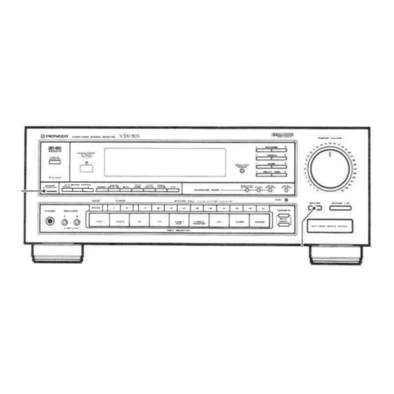
AUDIO/VIDEO STEREO
RECEIVER
VSX-5O1
VSX-511S
-
o
The demonstration mode is
activated
by
turning
on
the
power
switch
while holding
down the
RETURN
button
(from
power
standby condition).
The
demonstration will
appear on
the
display.
.
Press
the
POWER
switch
to
cancel
the
demonstration.
.
Activating the demonstration mode
causes
memory contents
to
return
to their
original default
condition
except tuner.
.
lllustration
shows
model
VSX-501.
Thank you
for
buying
this
Pioneer
product.
Please read
through
these
operating instructions
so
you will know how
to
operate
your
model properly.
After you
have finished reading the
instructions,
put
them away
in
a
safe place
for future
reJerence.
ln some countries or regions, the
shape
of the power plug and power
outlet may
sometimes
differ from
that
shown in
the
explanatory
drawings. However, the method of connecting
and
operating the unit
is
the
same.
WARNING:
To
pREVENT
FIRE
oR
sHocK
HAZARD,
Do
Nor
EXPOSE
THIS APPLIANCE
TO
RAIN
OR MOISTURE.
IMPORTANT NOTICE
lFor U.S. and Canadian modelsl
The serial number for
this
equipment
is
located
on
the
rear panel.
Please
write this
serial
number
on
your enclosed warranty card
and keep
it
in
a
secu[e area. This is
for your
security.
Note
to CATV system
installer
This reminder
is
provided to
call
the CATV system installer's attention
to
Article
82O-4O
of the
NEC
that
provides
guidelines
for
proper
grounding and, in particular, specifies
that the
cable ground shall
be
connected to
the
grounding
system
of
the
building,
as
close
to the point
of
cable
entry
as practical.
lFor Canadian modell
CAUTION: ro
pREVENT
ELEcrRtc
sHocK
Do
Nor
usE
rHts
(POLARIZED) PLUG
WITH AN
EXTENSION CORD, RECEPTACLE
OR
OTHER OUTLET UNLESS THE BLADES
CAN
BE
FULLY INSERTED TO
PREVENT
BLADE
EXPOSURE.
ATTENTION:
pouR
pREVENtR LES
cHocs
ELEcrRtouEs
NE
PAS UTILISER CETTE
FICHE POLARISEE
AVEC
UN PROLONGATEUR
UNE PRISE DE
COURANT OU
UNE
AUTRE
SORTIE DE
COURANT,
SAUF
SI LES
LAMES
PEUVENT ETRE INSEREES
A
FOND
SANS
EN
LAISSER
AUCUNE
PARTIE
A
DECOUVERT.
RETURN
function
This
function
returns
the
unit
to
a
set
of
initial settings and
ready
to
broadcast tuner. This
is
helpful during troubleshooting or when
no sound is
output.
For
details, refer
to
page
1
9.
() rrloNeerl'
The Art
of
Entertainment
Advertisement
Table of Contents

Related Manuals for Pioneer VSX-511S


Summary of Contents for Pioneer VSX-511S
-
Page 1: Connections
AUDIO/VIDEO STEREO RECEIVER VSX-5O1 VSX-511S shows VSX-501. lllustration model The demonstration mode is activated turning power (from switch while holding down the button power RETURN standby condition). demonstration will appear on display. Press POWER switch cancel demonstration. Activating the demonstration mode... - Page 2 DAMAGE REOUIRING SERVICE appliance INSTRUCTIONS operatins FOLLOW an antenna discharge unit, size grounding serviced by Pioneer authorized service followed should instructions shou antenna discharge conductors, location unit, center or qualified service personnel when: MOISTURE The appliance...
-
Page 3: Table Of Contents
CONTENTS SWITCHES ..ADJUST THE POSITION OF THESE BEFORE OPERATING, FEATURES ..5 ITEMS ..... ACCESSORY DTAGRAM ..BLOCK EFFECT ,..SURROUND LOGTC ....DOLBY MODE ..... DOLBY PRO LOGIC SURROUND, DOLBY LOGIC CENTER INSTALLATION....7 SPEAKER STEREO ..... SIMULATED ..8 connections .. - Page 4 BEFORE OPERATING. ADJUST THE POSITION OF THESE SWITCHES TWO VOLTAGE SELECTOR SWITCHES CHANNEL STEP/FM DE EMPHASIS SWITCH (Not available on U.S. and Canadian models) Only multi-voltage provided models are with these switches. U.S., Canadian, European, U.K. and Australian not provided models with unit...
-
Page 5: Features
LARGE, MOTOR-DRIVEN REMOTE CONTROL UNIT large volume knob contributes operational convenience With the attached remote control unit you can operate any audio Pioneer positive response. You can even operate it via control. remote When video component bearing mark. the volume setting... -
Page 6: Block Dtagram
BLOCK DIAGRAM VIDEO AUDIO o-.Fnffi-l-- exoro@@< co(9- rAPEI(_ LD(F vcR2(H rv(F F__n",. EFFECT SURROUND LOGIC SURROUND DOLBY Thisunithasabuilt-insurroundprocessorforaddingpresenceandan Discs and effect to the sound. expansive yback. size STUDIO: crosstalk, music in recording effect of listening enjoy the position this Select studio. -
Page 7: Dolby Pro Logic Surround, Dolby 3Ch Logic Center Mode
DOLBY PRO LOGIC SURROUND. DOLBY 3CH LOGIC CENTER MODE DOLBY PRO LOGIC SUFROUND clnter spesker: using a When the following settings: You can choose Jrom to the center which would have been sent PHANTOM The signal Mode Ghoices: Center front speakers' the left and right... - Page 8 When you find damaged, Check your your dealer nearest authorized servicd center PIONEER replacement. <AR81378>...
-
Page 9: Connections
CONNECTIONS ANTENNA NOTE FOR T.TYPE BASIC AUDIO SYSTEM CONNECTIONS wall, Stretch the antenna full length, affix etc. ANTENNA NOTE FOR LOOP placed at distance from the receiver, and should antenna should allowed to touch metallic objects. Avoid placing players, personal computers, television sets, near Accessory and other devices generating radio... - Page 10 CONNECTIONS BASIC VIDEO SYSTEM CONNECTIONS monitor V DEO ol-] VSX-501/VSX-s11S tuner <AR81378>...
- Page 11 Release lever. vsx-5014/sx-51 affir@ ri+ill, ,,., NOTE: super S-Wl When connecting woofer svstem such as the Pioneer OOO, the same speaker terminals (A or B) which front connect the front speakers are connected, Connecting speakers super woofet system to...
-
Page 12: Applications
CONNECTIONS APPLICATIONS NOTE: will DOLBY LOGIC SURROUND DOLBY LOGIC if the through graphic operate correctly signal passes equalizer. When using DOLBY PRO LOGIC SURROUND or DOLBY 3CH LOGIC, turn off button or set the graphic the TAPE MONITOR equalizer "through" for flat response to its... - Page 13 CONNECTIONS MULTI-ROOM CONNECTIONS NOTE: lSet-up examplel make wrong connections careful IN/OUT (black) MULTI- CONTROL ROOM REMOTE lgreen). Speakers Speakers Remote control unit Speakers A jacks of connect CONTROL a CD player or other components, such (including VSX-501 A/V system cassette deck, bearing the mark,...
- Page 14 FM/AM ANTENNA terminats @voeo MoNtroRljack these antenna terminals reception normal and AM Connect monitor TV or TV sets with video input terminals broadcasts. watching program materials from player connected , 2 or to this unit. 2 MoNtToR jacks @rnee jacks Connect second cassette deck @vcn...
-
Page 15: Speaker Installation
VCR component source, connect the AUDIO INPUT used recording. this jack other components (main unit Connect Pioneer remote control unit) when using those components IVIDEO control playing, this When monitoring the video image from... - Page 16 REAR PANEL FACILITIES NOTE: plug power from disconnected by removing This unit should socket e.g. vacation. wall when in regular use, when powet consumption such connect appliances with high television sefs order to heaters, irons, these OUTLETS avoid overheating and fire risk.
- Page 17 FRONT PANEL FACILITIES AUTo/MoNo POWER STANDBY/ON switch/STANDBY indicator button rvlooe the switch for electric power. This select the auto stereo mode when monaural mode listening When set to the position, power supplied and the when the FM broadcasts. The monaural mode has been selected unit becomes operational.
- Page 18 FRONT PANEL FACILITIES @STAT|ON CALL buttons @ DELAv TIME buttons to 30 FM or stations can be preset random. Operates when the DOLBy pRO STMULATED SURROUND LOGTC These buttons are used preset recall desired broadcasting SURROUND mode is stations, FM AUTO/MONO mode. time in g steps.
- Page 19 FRONT PANEL FACILITIES button RETURN (See page 26) @ACOUSTIC buttons this button to return the receiver into the initial state, TUNER Press MEMORY: using at this initial state. Adjust sound level selected the sound quality this button will the memorization Pressing result MASTER VOLUME...
- Page 20 FRONT PANEL FACILITIES ffiF^nt MoDE indicators @ cnnnncrER/LEVEL/BALANcE disptay CENTER center mode (NORMAL, WIDE, PHANTOM) during with the These display This displays name of component selected INPUT and DOLBY LOGIC operation and V-SIGNAL etc. DOLBY PRO LOGIC SURROUND SELECTOR SELECTOR, (Refer page level and balance settings during adjustment.
-
Page 21: Direct Access
auto stereo reception and monaural reception switch to the ON position. Press POWER With INPUT SELECTOR. time you AUTO/MONO buton, TUNER press MODE Each SCICCT to turn the TAPE MONITOR button when listening goes out. Be sure display section lights MONO indicator in . -
Page 22: Manual Tuning
MANUAL TUNING "+" FM/AM button choose either or AM. button pressed, BAND Each time the TUNING tuning (the AUTO Select ManualTuning with AUTO/MANUAL button to find stations manually. frequency step, allowing changes indicator goes outl. TUNING "-" +" " theTUN|NG button necessoryto Pressthe to the frequency of the... -
Page 23: Hits (Hyper Lntelligent Tuning System)
TUNING PRESET Last station memory MEMORY SCAN turn the power on, switch pressed When last POWER off will the power was previously turned station received before consecutive broadcast stations memorized in STATION Reception tuned again. (each buttons station is received about five CALL... -
Page 24: Receiving Fm Simulcast Tv Programs
FM SIMULCAST RECEIVING PROGRAMS combining set and {or TV tuner), you can receive TV proglam a VCR Select with the TV desired set. simulcast TV programs (stereo sound transmitted from an FM radio Tune in desired FM simulcast program on receiver. -
Page 25: Recording With Acassette Deck
RECORDING WITH CASSETTE DECK WITH TAPE 1/DAT RECORDING USING VCR 2 AUDIO RECORDING lf the TAPE button press to turn jacks MONITOR is ON, signal output from the VCR AUDIO OFF. The audio and VCR 2 jacks, same that output from the so you TAPE /DAT... - Page 26 the D0 with video or audio sofrware bearing FaBy sunnorrNp-l the lemote control Press TEST TONE button. mark. With the remote conrrol BALANCE (1, R), CENTER LEVEL DOLBY PRO LOGIC SURROUND when rear speakers LEVEL buttons, REAR adjust test tone volume level connected, DOLBY...
- Page 27 Select component want listen with the INPUT SELECTOR buttons. When listening recording) AM or FM broadcasts, press desired STATION CALL switch if the station has been preset. desired station been preset, tune the station using Auto or Manual Direct Access tuning. Select video component...
- Page 28 ON and signals components bearing Auto called by source contml ffimark output through unit's this you connect pioneer component bearing mark, such as jack, CONTROL OUT to connect be sure control cord kefer !t!=il CD player, to the jack on...
-
Page 29: Hints For Better Reception
HINTS FOR BETTER RECEPTION FM outdoor antenna Groun noise. lyvinyl insulated wire to the termin metal water pipe or grounding coaxial cable and bury NOTE: Nevet connect a wire pipe grounding since sparks may ignite the gas. Connecting feeder lf it possible to obtain adequate... - Page 30 LOADING BATTERIES REMOTE CONTROL RANGE point the Open rear cover. When operating remote control unit, front the unit the front panel of the receiver. The remote control unit may be used lnstall (R03/UM-4) batteries, correctly size matching (23 feet) from the within a about 7 range...
- Page 31 VSX-501 REMOTE CONTROL OPERATION Durins DOLBY LOGTC SURROUND and STMULATED SURROUND operation, delay time settings can from changed 16 ms in 2 ms steps. The DELAY TIME button does not work with STUDIO and DOLBy LOGTC. v-sEL (vtDEo stcNAL sELEcroR)/TEST ToNE button lTransmit mode: AUDIOI just...
- Page 32 VSX-501 REMOTE CONTROL OPERATION AUDIO mode operation buttons indicated by white characters, and VIDEO mode operation buttons indicated by green characters. Transmit Set the mode selector switch AUDIO. AUEIICD..VtEtEo function buttons (operation TUNER FM/AM Tuner) (UP) TAPE /vcF STATION button: TAPE EELECT t-r t-t...
- Page 33 VSX-501 REMOTE CONTROL OPERATION CD PLAYER OPERATION Transmit mode selector switch AUDIO. buttons (Operation CD Function CD playerl button: TAPEIVCP POWER TAFE Switches CD player power EELECT ON/OFF. r---r r----l only This CD player which you can switch applies ON/OFF remote control operation.
- Page 34 VSX.sOl REMOTE CONTROL OPERATION CASSETTE DECK OPERATION the Transmit mode selector switch auElto..vrE,Eo FirT] function buttons (Operation TAPE cassette deck) TAPE SELECT button: TAFE 9ELECT Selects cassette No.('l multi_cassette changer. "F_*R -vcFt cH+ DETKI EECKN < f-r t-t r--t Selects reverse playback. t--l (STOP) button;...
- Page 35 LOADING BATTERIES Never mix new and used batteries. Open the battery compartment cover the real of the remote Batteries of the same size have different voltages, depending control unit. The cover should open easily you slide their type. not mix different types batteries.
-
Page 36: Receiver Control Buttons
PIONEER's common system remote control units marked with VSX-s11S REMOTE CONTROL OPERATION symbol RECEIVER CONTROL BUTTONS TDOLBY PRO LOGIC SURROUND] NORMAL- W|DE PHANTOM IDOLBY LOGIC] NoRMAL- wtDE___-_l [--..-----_ €) DELAY TtME butron Durins DOLBY... -
Page 37: Operating Other Components
VSX-511S REMOTE CONTROL OPERATION OPERATING OTHER COMPONENTS REMOTE CONTROLLING OTHER OF VIA THIS YOUR AUDIO-VISUAL COMPONENTS UNIT REOUIRES: (have components must be remote controllable sensor window front panel) command from this on the receive direct unit, upon successful those commands... - Page 38 VSX-511S REMOTE CONTROL OPERATION playar operation button: POWER Switches LD player power ON/OFF. ts< (CHAPTER button SKIP) Searches for the start of the chapter playing. >H (CHAPTER button SKIP) for the start of the Searches next chapter. FowEF -#3=o' button: SEARCH "6"'d...
- Page 39 VSX-s11S REMOTE CONTROL OPERATION CD player operation button: POWER power Switches CD player ON/OFF. t<< (TRACK SEARCH) button: the track currently in playing. Returns to the beginning of >H (TRACK SEARCH) button: to the Advances next track. MU!TI -#3=ot COMMAf,I' fast Selects backward.
-
Page 40: Programming
EDIT MODE this will situations. But as a rule, be able Pioneer orTV special the VCR CONTROL MODE, MODE: 1, VCR PRESET most system control needs, including video well of the... - Page 41 VSX-511S REMOTE CONTROL OPERATION Learning capacity and buttons that learn During the learning operation, press button buttons shown the diagram can learn. changing the CONTROL twice, or move remote control, possible. correct learning MODE, single button can be used learn...
- Page 42 ED|T mode canceled. ..Aftet prcsetting, you LEARN mode memorize Button functions same as pioneer,s unified remote control code functions, so tefer page concerning TV functions, page Remote control codes concerning VCR functions. of other manufacturers preset...
- Page 43 VSX-s11S REMOTE CONTROL OPERATION MULTI-EDIT MODE TO THE INITIAL SETTINGS RETURNING can be programmed into maximum seven commands MULTI transmitted COMMAND button. This enables series signals particular CONTROL MODES lnitialization pushing MULTI COMMAND button. simply the battery compartment cover. Remove the cover, press pressing...
-
Page 44: Troubleshooting
PIONEER dealer work. carry repair Symptom Remedy Cause Power does not come on even Power cord is disconnected. - Page 45 TROUBLESHOOTING Remedy Cause Symptom Set correctly. switch incorrectly. rear sound is produced. SURROUND MODE with remote control turned down. Adjust the rear level REAR LEVEL is unit's buttons. REAR LEVEL from wires Connect wires terminals securely. Speaker connecting disconnected terminals. REAR SPEAKERS no batteries in remote lnsert...
-
Page 46: Specifications
SPECIFICATIONS Amplifier section FM Tuner Section Range...,,..Continuous average power output of 100 watts* ..87.5 Frequency (0.95 Sensitivity....pvl75 Mono; 10.8 dBf, Usable from 20 to 20,000 channel, min., at ohms, Sensitivity Mono; 15.3 dBf, pVl75 dB Ouieting with no than 0.05 total more... - Page 47 €noo fnqe ts Bqt(K -lt+t,...
- Page 48 Aftcr loss all, we \\'anr vou listening frrr a Iilerimc. Published by Pioneer Electronic Corporation. Copyright O Pioneer Electronic Corporation rights reserved. PIONEER ELECTRONIC CORPORATION 4-1, Meguro 1-Chome, Meguro-ku, Tokyo Japan 153, lNC.