Table of Contents
Advertisement
User's
Manual
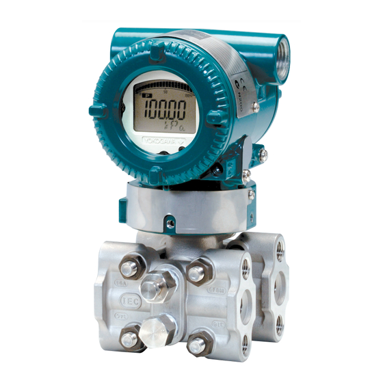
EJX and EJA-E Series
Differential Pressure and
Pressure Transmitters
Installation Manual
Contents
1.
1.1
1.2
1.3
2.
2.1
2.2
2.3
2.4
2.5
2.6
2.7
3.
3.1
3.2
3.3
3.4
3.5
3.6
3.7
4.
4.1
4.2
4.3
5.
5.1
5.2
5.3
5.4
5.5
5.6
6.
6.1
6.2
7.
8.
CD-ROM included
IM 01C25A01-01E
For Safe Use of Product . .............................................2
Warranty . .....................................................................3
ATEX Documentation . .................................................4
Model and Specifications Check . ................................6
Selecting the Installation Location ..............................6
Pressure Connection ..................................................6
EMC Conformity Standards ..................................... 15
Pressure Equipment Directive (PED) ...................... 16
Low Voltage Directive . .............................................. 17
Mounting................................................................... 18
Mounting the Diaphragm Seals ......................................18
Diaphragm Seals Installation Consideration . ........... 19
Mounting the Flushing Connection Ring . ................. 20
Affixing the Teflon Film ............................................. 21
Rotating Transmitter Section . ................................... 22
Changing the Direction of Integral Indicator............. 22
Impulse Piping Installation Precautions ................... 23
Impulse Piping Connection Examples ..................... 25
Wiring Precautions ................................................... 28
Wiring ....................................................................... 30
RTD Cable Connection (EJX910A/EJX930A) . ........ 31
Grounding ................................................................ 34
Power Supply Voltage and Load Resistance . .......... 34
Preparation for Starting Operation ........................... 35
Zero Point Adjustment . ............................................. 36
IM 01C25A01-01E
7th Edition
1
2
3
4
5
6
7
8
Advertisement
Table of Contents

Related Manuals for YOKOGAWA EJX Series


Summary of Contents for YOKOGAWA EJX Series
-
Page 1: Table Of Contents
User’s Manual EJX and EJA-E Series Differential Pressure and Pressure Transmitters Installation Manual CD-ROM included IM 01C25A01-01E Contents Introduction 1.1 For Safe Use of Product ..........2 1.2 Warranty ..............3 1.3 ATEX Documentation ..........4 Handling Cautions 2.1 Model and Specifications Check .........6 2.2 Selecting the Installation Location ......6 2.3 Pressure Connection ..........6 2.4 Installation of an Explosion-Protected Instrument ..6 2.5 EMC Conformity Standards ........15 2.6 Pressure Equipment Directive (PED) ...... 16 2.7 Low Voltage Directive . -
Page 3: Introduction
<Contents of product specific manuals> • All rights reserved. No part of this manual may be • Installation • BT200 operation reproduced in any form without Yokogawa’s written • Impulse piping installation • Maintenance • Wiring • Specifications permission. • Zeroing • Yokogawa makes no warranty of any kind with regard F0101.ai to this manual, including, but not limited to, implied warranty of merchantability and fitness for a particular Table 1.1 PDF Manual List and Applicable Style Code purpose. Models Document No. Style • If any question arises or errors are found, or if any EJX110A information is missing from this manual, please... -
Page 4: For Safe Use Of Product
<1. Introduction> 1.1 For Safe Use of Product • Yokogawa assumes no responsibilities for this product except as stated in the warranty. For the protection and safety of the operator and the • If the customer or any third party is harmed by the use instrument or the system including the instrument, please of this product, Yokogawa assumes no responsibility be sure to follow the instructions on safety described for any such harm owing to any defects in the product in this manual when handling this instrument. In case which were not predictable, or for any indirect the instrument is handled in contradiction to these damages. instructions, Yokogawa does not guarantee safety. • When describing the model name like EJ Please give your attention to the followings. in this manual, it shows the applicability for both EJX110A and EJA110E. The same representations (a) Installation are used for the other models, too. • The instrument must be installed by an expert engineer or a skilled personnel. The procedures NOTE described about INSTALLATION are not permitted for operators. For F Fieldbus and PROFIBUS PA protocol OUNDATION • In case of high process temperature, care should versions, please refer to manuals in the attached CD- be taken not to burn yourself because the surface of ROM, in addition to this manual. -
Page 5: Warranty
Instrument) of this manual. data and other information you can include in your • The use of this instrument is restricted to those who communication will also be helpful. have received appropriate training in the device. • Responsible party for repair cost for the problems • Take care not to create sparks when accessing the shall be determined by Yokogawa based on our instrument or peripheral devices in a hazardous investigation. location. • The Purchaser shall bear the responsibility for (f) Modification repair costs, even during the warranty period, if the • Yokogawa will not be liable for malfunctions or malfunction is due to: damage resulting from any modification made to this - Improper and/or inadequate maintenance by the instrument by the customer. purchaser. - Failure or damage due to improper handling, use or storage which is out of design conditions. - Use of the product in question in a location not conforming to the standards specified by Yokogawa, or due to improper maintenance of the installation location. - Failure or damage due to modification or repair by any party except Yokogawa or an approved representative of Yokogawa. -
Page 6: Atex Documentation
<1. Introduction> 1.3 ATEX Documentation This is only applicable to the countries in European Union. IM 01C25A01-01E... -
Page 7: Handling Cautions
<2. Handling Cautions> Handling Cautions When the transmitter is delivered, visually check them EJ110 to make sure that no damage occurred during shipment. EJ120 Also check that all transmitter mounting hardware shown EJ130 - - EJ310 in Figure 2.1 is included. If the transmitter was ordered EJ430 without the mounting bracket or without the process EJ440 connector, the transmitter mounting hardware is not included. Table 2.1 Applicable Model Code for Mounting Hardware EJX910A - - EJX930A Applicable Suffix code Part name model EJ110 Process connector bolt EJ120 Process Process connector EJ130 connections EJ210... -
Page 8: Model And Specifications Check
NOTE Location For F Fieldbus and PROFIBUS PA explosion oundation protected type, please refer to manual in the attached The transmitter is designed to withstand severe CD-ROM. environmental conditions. However, to ensure that it will provide years of stable and accurate performance, take If a customer makes a repair or modification to an the following precautions when selecting the installation intrinsically safe or explosionproof instrument and the location. instrument is not restored to its original condition, its (a) Ambient Temperature intrinsically safe or explosionproof construction may be Avoid locations subject to wide temperature variations compromised and the instrument may be hazardous to or a significant temperature gradient. If the location is operate. Please contact Yokogawa before making any exposed to radiant heat from plant equipment, provide repair or modification to an instrument. adequate thermal insulation and/or ventilation. (b) Ambient Atmosphere CAUTION Do not install the transmitter in a corrosive atmosphere. If this cannot be avoided, there must be This instrument has been tested and certified as adequate ventilation as well as measures to prevent being intrinsically safe or explosionproof. Please the leaking of rain water and the presence of standing note that severe restrictions apply to this instrument’s water in the conduits. construction, installation, external wiring, maintenance and repair. A failure to abide by these restrictions could (c) Shock and Vibration make the instrument a hazard to operate. Although the transmitter is designed to be relatively resistant to shock and vibration, an installation site should be selected where this is kept to a minimum. - Page 9 • Note a warning label worded “SUBSTITUTION and Class I, Zone 2, Groups IIC, in Hazardous OF COMPONENTS MAY IMPAIR INTRINSIC Locations. SAFETY,” and “INSTALL IN ACCORDANCE WITH • Outdoor hazardous locations: NEMA TYPE 4X DOC. No. IFM022-A12” • Temperature Class: T4 • Ambient temperature: –60 to 60°C Note 4. Maintenance and Repair • The instrument modification or parts replacement Note 2. Entity Parameters by other than authorized representative of • Intrinsically Safe Apparatus Parameters Yokogawa Electric Corporation is prohibited and [Groups A, B, C, D, E, F and G] will void Factory Mutual Intrinsically safe and Vmax = 30 V Ci = 6 nF Nonincendive Approval. Imax = 200 mA Li = 0 µH Pmax = 1 W [Intrinsically Safe] Hazardous Location Nonhazardous Location * Associated Apparatus Parameters (FM approved barriers)
- Page 10 C & D, Class II, Division 2, Groups E, F & G, Class WARNING: OPEN CIRCUIT BEFORE III, Division 1 REMOVING COVER. FACTORY SEALED, • Enclosure: Type 4X CONDUIT SEAL NOT REQUIRED. INSTALL IN • Temp. Code: T4 ACCORDANCE WITH THE USERS MANUAL IM • Amb. Temp.: –50* to 60°C 01C25. * –15°C when /HE is specified. • Take care not to generate mechanical sparking • Process Temperature: 120°C max. when accessing to the instrument and peripheral [For CSA E60079] devices in a hazardous location. • Applicable Standard: CAN/CSA E60079-11, Note 4. Maintenance and Repair CAN/CSA E60079-15, IEC 60529:2001 • The instrument modification or parts replacement • Ex ia IIC T4, Ex nL IIC T4 by other than authorized representative of • Ambient Temperature: –50 to 60°C Yokogawa Electric Corporation is prohibited and • Max. Process Temp.: 120°C will void Factory Mutual Explosionproof Approval. • Enclosure: IP66/IP67 IM 01C25A01-01E...
- Page 11 Note 2. Wiring • Installation should be in accordance with Canadian • All wiring shall comply with Canadian Electrical Electrical Code Part I and Local Electrical Code. Code Part I and Local Electrical Codes. • Dust-tight conduit seal must be used when • In hazardous location, wiring shall be in conduit as installed in Class II and III environments. shown in the figure. • The instrument modification or parts replacement • WARNING: by other than authorized representative of A SEAL SHALL BE INSTALLED WITHIN 50cm OF Yokogawa Electric Corporation and Yokogawa THE ENCLOSURE. Corporation of America is prohibited and will UN SCELLEMENT DOIT ÊTRE INSTALLÉ À void Canadian Standards Intrinsically safe and MOINS DE 50cm DU BOÎTIER. nonincendive Certification. • WARNING: [Intrinsically Safe] WHEN INSTALLED IN CL.I, DIV 2, SEAL NOT Hazardous Location Nonhazardous Location REQUIRED. Group IIC, Zone 0 UNE FOIS INSTALLÉ DANS CL I, DIV 2, AUCUN...
- Page 12 UTILISEZ DES CÂBLES RÉSISTANTES Á LA T85°C (Tp.: 80°C) CHALEUR ≥ 90°C. T100°C (Tp.: 100°C) • Take care not to generate mechanical sparking T120°C (Tp.: 120°C) when accessing to the instrument and peripheral • Enclosure: IP66 / IP67 devices in a hazardous location. Note 2 Electrical Data Note 4. Maintenance and Repair • In type of explosion protection intrinsic safety Ex ia • The instrument modification or parts replacement IIC or Ex ia IIIC, only for connection to a certified by other than authorized representative of intrinsically safe circuit with following maximum Yokogawa Electric Corporation and Yokogawa values: Corporation of America is prohibited and will void Ui = 30 V Canadian Standards Explosionproof Certification. Ii = 200 mA Pi = 0.9 W c. CSA Intrinsically Safe Type/CSA (Linear Source) Explosionproof Type Maximum internal capacitance; Ci = 27.6 nF Model EJX/EJA-E Series pressure transmitters with Maximum internal inductance; Li = 0 µH optional code /CU1 or /V1U1 can be selected the Note 3. Installation type of protection (CSA Intrinsically Safe or CSA • Refer to the control drawing. All wiring shall comply...
- Page 13 • No. KEMA 06ATEX 0037X shall be used that are suitable for the application • Applicable Standard: and correctly installed. EN 50014:1997, EN 50020:2002, EN 50284:1999, EN 50281-1-1:1998 Note 4. Maintenance and Repair • Type of Protection and Marking code: • The instrument modification or parts replacement EEx ia IIC T4 by other than authorized representative of • Group: II Yokogawa Electric Corporation is prohibited and • Category: 1G, 1D will void KEMA Intrinsically safe Certification. • Ambient Temperature for gas-proof: Note 5. Special Conditions for Safe Use –50* to 60°C • In the case where the enclosure of the Pressure * –15°C when /HE is specified. • Process Temperature (Tp.): 120°C max. Transmitter is made of aluminium, if it is mounted • Maximum Surface Temperature for dust-proof: in an area where the use of category 1 G T85°C (Tamb.: –40* to 60°C, Tp.: 80°C) apparatus is required, it must be installed such, T100°C (Tamb.: –40* to 60°C, Tp.: 100°C)
- Page 14 WARNING with a dry cloth on coating face of the product. • In the case where the enclosure of the Pressure To satisfy IP66 or IP67, apply waterproof glands to the Transmitter is made of aluminium, if it is mounted electrical connection port. in an area where the use of category 2D apparatus is required, it shall be installed in such a way that the risk from electrostatic discharges and c. ATEX Flameproof Type propagating brush discharges caused by rapid Caution for ATEX flameproof type. flow of dust is avoided. • The instrument modification or parts replacement Note 1. Model EJX/EJA-E Series pressure transmitters by other than an authorized Representative of with optional code /KF22 for potentially Yokogawa Electric Corporation is prohibited and explosive atmospheres: will void the certification. • No. KEMA 07ATEX0109 X • To satisfy IP66 or IP67, apply waterproof glands to • Applicable Standard: EN 60079-0:2009, the electrical connection port. EN 60079-1:2007, EN 60079-31:2009 • Type of Protection and Marking Code: Ex d IIC T6...T4 Gb, Ex tb IIIC T85°C Db • Group: II • Category: 2G, 2D IM 01C25A01-01E...
- Page 15 • Overvoltage category: I Note 1. Electrical Data Ui = 30 V Ci = 27.6 nF Location of the mark Li = 0 µH F0214.ai Note 2. Installation • All wiring shall comply with local installation (3) Installation requirements. (refer to the control drawing) • Cable glands, adapters and/or blanking elements WARNING shall be of Ex “n”, Ex “e” or Ex “d” and shall be installed so as to maintain the specified degree of • All wiring shall comply with local installation protection (IP Code) of the transmitters. requirements and the local electrical code. Note 3. Maintenance and Repair • There is no need for conduit seal in Division 1 • The instrument modification or parts replacement and Division 2 hazardous locations because this by other than authorized representative of product is sealed at the factory. Yokogawa Electric Corporation is prohibited and will void ATEX intrinsically safe. IM 01C25A01-01E...
- Page 16 STYLE: Style code. devices in a hazardous location. SUFFIX: Specified suffix code. SUPPLY: Supply voltage. OUTPUT: Output signal. (5) Maintenance and Repair MWP: Maximum working pressure. CAL RNG: Specified calibration range. WARNING NO.: Serial number and year of production TOKYO 180-8750 JAPAN: The manufacturer name and the address The instrument modification or parts replacement by other than an authorized Representative of Yokogawa *1: The first number in the second block of “NO.” column is the last one number of the production year. Electric Corporation is prohibited and will void the certification. second block (6) Name Plate NO. 91K819857 Name plate The year 2011 *2: “180-8750” is a zip code which represents the following address. 2-9-32 Nakacho, Musashino-shi, Tokyo Japan *3: The identification number of Notified Body. Tag plate for flameproof type 2.4.4 IECEx Certification...
-
Page 17: Emc Conformity Standards
Intrinsically safe and type n certification. • Take care not to generate mechanical sparking when accessing to the instrument and peripheral [Intrinsically Safe] devices in a hazardous location. Hazardous Location Nonhazardous Location Group IIC, Zone 0 Note 4. Maintenance and Repair General • The instrument modification or parts replacement IECEx certified Purpose EJX Series Pressure by other than authorized representative of Safety Barrier Equipment Transmitters Yokogawa Electric Corporation is prohibited and will void IECEx Certification. – – – – Supply 2.5 EMC Conformity Standards F0216.ai... -
Page 18: Pressure Equipment Directive (Ped)
<2. Handling Cautions> 2.6 Pressure Equipment Capsule PS.V Model V(L) Category* code (bar) (bar.L) Directive (PED) EJ440 with code / C, D (1) General Article 3, A, B, C EJ510 • EJX/EJA-E Series pressure transmitters are Paragraph 3 EJX610A categorized as piping under the pressure accessories (SEP) section of directive 97/23/EC, which corresponds to EJ510, EJX610A Article 3, Paragraph 3 of PED, denoted as Sound with code / Engineering Practice (SEP). • EJX110A-MS, EJX110A-HS, Article 3, A, B, C EJ530, EJX110A-VS, EJA110E with /HG, EJ130, Paragraph 3 EJX630A EJ440, EJ510-D, EJ530-D, (SEP) EJX610A-D, and EJX630A-D can be used above... -
Page 19: Low Voltage Directive
<2. Handling Cautions> 2.7 Low Voltage Directive Applicable standard: EN61010-1 (1) Pollution Degree 2 "Pollution degree" describes the degree to which a solid, liquid, or gas which deteriorates dielectric strength or surface resistivity is adhering. " 2 " applies to normal indoor atmosphere. Normally, only non- conductive pollution occurs. Occasionally, however, temporary conductivity caused by condensation must be expected. (2) Installation Category I "Overvoltage category(Installation category)" describes a number which defines a transient overvoltage condition. It implies the regulation for impulse withstand voltage. " I " applies to electrical equipment which is supplied from the circuit when appropriate transient overvoltage control means (interfaces) are provided. IM 01C25A01-01E... -
Page 20: Installation
<3. Installation> Installation Vertical pipe mounting Vertical pipe mounting IMPORTANT (Process connector upside) (Process connector downside) • When welding piping during construction, take care not to allow welding currents to flow through Mounting the transmitter. bracket • Do not step on this instrument after installation. 50 mm • For EJ430, EJ440 and EJ438, (2-inch) pipe the atmospheric opening is located on the low U-bolt nut pressure side cover flange. For EJ530 and U-bolt EJX630A whose capsule code is A, B, or C, the pipe of the atmospheric opening is located on the Transmitter pressure detecting section. These openings must mounting bolt F0303.ai not face upward. -
Page 21: Diaphragm Seals Installation Consideration
<3. Installation> 3.3 Diaphragm Seals Installation 3.2.1 EJ210 Consideration The transmitter is mounted on a process using its high pressure side flange as shown in Figure 3.5. The IMPORTANT customer should prepare the mating flange, gasket, stud bolts and nuts. • When measuring the liquid level of the tank, the minimum liquid level (zero point) must be set to a level at least 50 mm above the center of the high Gasket pressure side diaphragm seal (see Figure 3.7). • Correctly install the diaphragm seals on the high and low pressure sides of the process, checking the label on each seal. • To avoid measuring error duets temperature Stud bolt difference between the two diaphragm seals, capillary tube must be bound together. The F0305.ai capillary tube must be securely fixed to the tank Figure 3.5 EJ210 Mounting wall to prevent movement by wind or vibration. If the capillary tube is too long, loosely coil the 3.2.2 EJ118 and EJ438 extra tube portion (coil diameter of 300 mm or more) and secure the coiled tube with a clamp. Mount the diaphragm seals using the flanges as shown in Figure 3.6. The mating flange, gasket, bolts and nuts are to be procured by the customer. IMPORTANT pressure Flange... -
Page 22: Mounting The Flushing Connection Ring
<3. Installation> IMPORTANT Low pressure side The transmitter should be installed at least 600 mm below the high pressure (HP) process connection to ensure a positive head pressure of fill fluid. Pay special attention to High vacuum applications. pressure side If it can not be installed at least 600 mm below the HP process connection, please use the equation below: (P–P0) (–) × 0.102 [mm] h: Vertical height between the HP process connection and the transmitter (mm) F0308.ai h≤0: I nstall the transmitter at least h (mm) below the Figure 3.8 Example of Installation to Tank HP process connection (Caution on Installation) h>0: I nstall the transmitter at most h (mm) above the HP process connection 3.4 Mounting the Flushing P: Pressure in the tank (Pa abs) P0: Minimum working pressure limit of the transmitter (Pa Connection Ring abs) See below table. -
Page 23: Affixing The Teflon Film
<3. Installation> 3.5 Affixing the Teflon Film 3.4.2 Mounting to Process Flange Tighten the bolts to completely close the gap between the IMPORTANT ring and the pressure detector section. The mating flange, gasket, stud bolts and nuts are to The FEP Teflon option includes a teflon film and procured by the customer. fluorinated oil. Before mounting the transmitter to the process flange, affix the teflon film as follows: 1) Position the diaphragm seal so that the diaphragm Spiral gasket Mating flange is in an upward position. 2) Pour the fluorinated oil on the diaphragm and Ring gasket area covering it completely and evenly. Be careful not to scratch the diaphragm or change the its shape. 3) Affix the teflon film over the diaphragm and gasket area. 4) Next, carefully inspect the cover and try to identify Diaphragm any entrapped air between the diaphragm and the teflon film. The air must be removed to ensure Gasket Pressure-detector optimum performance. If air pockets are present, section use your fingers to remove the air by starting at the center of the diaphragm and work your way out. 5) Position the gasket on the Teflon film. -
Page 24: Rotating Transmitter Section
<3. Installation> 3.6 Rotating Transmitter Section 3.7 Changing the Direction of Integral Indicator The transmitter section can be rotated approximately 360° (180° to either direction or 360° to one direction IMPORTANT from the original position at shipment, depending on the configuration of the instrument.) It can be fixed at any Always turn OFF power, release pressure and angle within above range. remove a transmitter to non-hazardous area before 1) Remove the two setscrews that fasten the transmitter disassembling and reassmbling an indicator. section and capsule assembly, using the Allen wrench. An integral indicator can be installed in the following 2) Rotate the transmitter section slowly and stop it at three directions. designated position. 3) Tighten the two setscrews to a torque of 1.5 N·m. IMPORTANT Do not rotate the transmitter section more than the F0313.ai above limit. Figure 3.13 Integral Indicator Direction Vertical impulse piping type IMPORTANT Pressure-detector section The terminal box cover is locked by an Allen head Stopper bolt (a shrouding bolt) on ATEX flameproof type Rotate 0 to ±180°... -
Page 25: Installing Impulse Piping
<4. Installing Impulse Piping> Installing Impulse Piping 4.1 Impulse Piping Installation (3) Tightening the Process Connector Mounting Bolts Precautions After connecting an impulse line, tighten the process The impulse piping that connects the process connector mounting bolts uniformly. outputs to the transmitter must convey the process pressure accurately. If, for example, gas collects in (4) Removing the Impulse Piping Connecting a liquid-filled impulse line, or the drain of a gas-filled Port Dustproof Cap impulse line becomes plugged, it will not convey the The impulse piping connecting port on the transmitter is pressure accurately. Since this will cause errors in the measurement output, select the proper piping method covered with a plastic cap to keep out dust. This cap must for the process fluid (gas, liquid, or steam). Pay careful be removed before connecting the line. (Be careful not attention to the following points when routing the impulse to damage the threads when removing this cap. Never piping and connecting the impulse piping to a transmitter. insert a screwdriver or other tool between the cap and port threads to remove the cap.) 4.1.1 Connecting Impulse Piping to the Transmitter (5) Connecting the Transmitter and 3-Valve Manifold (for differential pressure (1) Check the High and Low Pressure transmitters) Connections on the Transmitter (Figure 4.1) A 3-valve manifold consists of two stop valves to block Symbols “H” and “L” have been placed on the capsule process pressure and an equalizing valve to equalize assembly to indicate high and low pressure side. With... - Page 26 <4. Installing Impulse Piping> 4.1.2 Routing the Impulse Piping 1) Screw nipples into the connection ports on the transmitter side of the 3-valve manifold, and into the impulse piping connecting ports on the process (1) Process Pressure Tap Angles connectors. (To maintain proper sealing, wind sealing If condensate, gas, sediment or other extraneous tape around the nipple threads.) material in the process piping gets into the impulse 2) Mount the 3-valve manifold on the 50 mm (2-inch) piping, pressure measurement errors may result. To pipe by fastening a U-bolt to its mounting bracket. prevent such problems, the process pressure taps must Tighten the U-bolt nuts only lightly at this time. be angled as shown in Figure 4.5 according to the kind of 3) Install the pipe assemblies between the 3-valve fluid being measured. manifold and the process connectors and lightly tighten the ball head lock nuts. (The ball-shaped ends NOTE of the pipes must be handled carefully, since they will not seal properly if the ball surface is scratched or • If the process fluid is a gas, the taps must be otherwise damaged.) vertical or within 45° either side of vertical. 4) Now tighten the nuts and bolts securely in the following sequence: • If the process fluid is a liquid, the taps must be Process connector bolts → transmitter-end ball head horizontal or below horizontal, but not more than lock nuts → 3-valve manifold ball head lock nuts → 45° below horizontal.
-
Page 27: Impulse Piping Connection Examples
<4. Installing Impulse Piping> 4.2 Impulse Piping Connection (4) Temperature Difference Between Impulse Piping (for differential pressure Examples transmitters) Figure 4.6, 4.7, and 4.8 shows examples of typical If there is a temperature difference between the high impulse piping connections. Before connecting the and low impulse lines, the density difference of the fluids transmitter to the process, study the transmitter in the two lines will cause an error in the measurement installation location, the process piping layout, and pressure. When measuring flow, impulse lines must be the characteristics of the process fluid (corrosiveness, routed together so that there is no temperature difference toxicity, flammability, etc.), in order to make appropriate between them. changes and additions to the connection configurations. (5) Condensate Pots for Steam Flow Note the following points when referring to these piping Measurement (for differential pressure examples. transmitters) • If the impulse line is long, bracing or supports should If the liquid in the impulse piping repeatedly condenses be provided to prevent vibration. or vaporizes as a result of changes in the ambient or • The impulse piping material used must be compatible process temperature, this will cause a difference in the with the process pressure, temperature, and other fluid head between the high pressure and low pressure conditions. sides. To prevent measurement errors due to these head • A variety of process pressure tap valves (main valves) differences, condensate pots are used when measuring are available according to the type of connection steam flow. - Page 28 <4. Installing Impulse Piping> (3) Removing the Process Connector Port Liquid Steam Dustproof Cap Tap valve Union or flange The process connector port threads are covered with a Union or flange plastic cap to exclude dust. This cap must be removed before connecting the piping. (Be careful not to damage Tap valve Drain plug the threads when removing this cap. Never insert a Drain valve screwdriver or other tool between the cap and port threads to remove the cap.) Union or 4.3.2 Routing the Process Piping flange (1) Relationship between Process Fluid and Manifold Locations (For the vertical Union or flange impulse piping type) Tap valve If condensate (or gas) generated in the process piping Drain valve Drain valve...
- Page 29 <4. Installing Impulse Piping> • A variety of process piping-mounted stop valves are available according to the type of connection (flanged, screwed, welded), construction (globe, gate, or ball valve), temperature and pressure. Select the type of valve most appropriate for the application. Union or flange Gas flow measurement Stop valve Manifold Process piping Liquid flow measurement Manifold Union or flange Stop valve Process piping F0410.ai Figure 4.10 Process Piping Connection Examples IM 01C25A01-01E...
-
Page 30: Wiring
<5. Wiring> Wiring 5.2 Connections of External NOTE Wiring to Terminal Box For F Fieldbus and PROFIBUS PA OUNDATION 5.2.1 Power Supply Wiring Connection communication types, please refer to manuals in the attached CD-ROM. Connect the power supply wiring to the SUPPLY + and – terminals. Transmitter terminal box 5.1 Wiring Precautions Power supply – IMPORTANT F0502.ai • Lay wiring as far as possible from electrical noise Figure 5.2 Power Supply Wiring Connection sources such as large capacity transformers, motors, and power supplies. 5.2.2 Configuration Tool Connection • Remove electrical connection dust cap before wiring. Connect the configuration tool to the SUPPLY + and • All threaded parts must be treated with – terminals. (Use hooks.) waterproofing sealant. (A non-hardening silicone group sealant is recommended.) Transmitter terminal box... - Page 31 <5. Wiring> 5.2.4 Connection Example for EJX910A and EJX930A Table 5.1 The connection example for simultaneous analog and pulse and alarm, status output. (For HART protocol type) Output Type Description Analog Output Transmitter Electrical Terminal Distributor In this case, Communication 24V DC is possible (up to a distance SUPPLY – of 2km when a CEV cable – 250Ω is used.) PULSE Pulse Output Transmitter Electrical Terminal Use the Three-wire shielded cable. Shielded Cable In this case, No communication is possible. SUPPLY – PULSE Electric counter Status Output Transmitter Electrical Terminal...
-
Page 32: Wiring
<5. Wiring> 5.2.5 External Temperature Connection (2) Intrinsically Safe Type (for EJX910A and EJX930A) With the intrinsically safe type, a safety barrier must be Connect the RTD cable assembly to the Juck Terminal. included in the loop. Hazardous Location Nonhazardous Location Transmitter terminal box Distributor (Power supply unit) F0505.ai Receiver Figure 5.5 External Temperature Connection instrument 5.3 Wiring Safety barrier F0508.ai 5.3.1 Loop Configuration Figure 5.8 Connection between Transmitter and Distributor Since the DPharp uses a two-wire transmission system, signal wiring is also used as power wiring. (3) Intrinsically Safe Type (for EJX910A and DC power is required for the transmitter loop. The EJX930A) transmitter and distributor are connected as shown below. -
Page 33: Rtd Cable Connection (Ejx910A/Ejx930A)
<5. Wiring> 5.3.2 Wiring Installation Gas sealing device Non-hazardous area (1) General-use Type and Intrinsically Safe Type Flameproof flexible metal conduit With the cable wiring, use a metallic conduit or waterproof Hazardous area glands. Apply a non-hardening Flameproof sealant to the threads of heavy-gauge • Apply a non-hardening sealant to the terminal box these fittings for steel conduit waterproofing connection port and to the threads on the flexible metal conduit for waterproofing. Seal fitting After wiring, impregnate the fitting Drain plug with a compound to seal tubing. - Page 34 <5. Wiring> • Components for the cable gland (4) Insert the RTD cable and firmly plug its connector into The cable gland assembly consists of an entry, seal, the connecting port in the transmitter's terminal box. running coupler, and backnut. Confirm that the seal is attached inside the entry and that the thread size of the cable gland is the same as that for the RTD electrical connection. 1/2NPT Type Running Entry with Seal Backnut Coupler F0519.ai (5) Align the running coupler on the entry. M20 Type Running Gasket Entry with Seal Backnut Coupler F0520.ai (6) Turn the running coupler until the seal in the entry comes into contact with the RTD cable. CAUTION Input/output signal is non-isolated. Do not turn on power supply until you complete all the wiring work. Procedure (1) Disassemble the cable gland: loosen the running F0521.ai coupler to separate the backnut from the entry.
- Page 35 <5. Wiring> 5.4.2 Connecting Shielded Cable for 5.4.3 Cable Connection RTD Terminal Box Conduit Use (External temperature Side input code: -B, -C, and -D) EJX multivariable transmitter RTD I/F is for 3-wire Type RTD, Pt100. • RTD connection components: EJX multivariable Heed the following when wiring an RTD of the 2- or 4-wire transmitter and RTD cable type. NOTE Please note that a temperature error will occur when you use a 2-wire RTD because of wiring resistance. Please do not ground the shield on the RTD side of the cable. F0522.ai Procedure CAUTION (1) R emove the protection cap protecting the RTD electrical connection and insert the RTD cable. Please use only the cables provided with this instrument. When wiring, be sure not to damage the cable's insulation or its core. All the cable cores must have sufficient insulation around them. Do not let the signal line contact the shield line. Do not allow the shield line or the signal line to come the earth potential voltage. F0523.ai (2) Remove the cap protecting the connecting port. Then insert the RTD cable and firmly plug the connector 2-Wire 3-Wire 4-Wire...
-
Page 36: Grounding
<5. Wiring> 5.5 Grounding Grounding is always required for the proper operation of transmitters. Follow the domestic electrical requirements as regulated in each country. For a transmitter with a built-in lightning protector, grounding should satisfy ground resistance of 10Ω or less. Ground terminals are located on the inside and outside of the terminal box. Either of these terminals may be used. Ground terminal (inside) Ground terminal (outside) F0525.ai Figure 5.14 Ground Terminals 5.6 Power Supply Voltage and Load Resistance When configuring the loop, make sure that the external load resistance is within the range in the figure below. (Note) In case of an intrinsically safe transmitter, external load resistance includes safety barrier resistance. E–10.5 External Communication 0.0244 load applicable range resistance BRAIN and HART R (Ω) 10.5 16.6 25.2... -
Page 37: Operation
<6. Operation> Operation Verify and Change Transmitter NOTE Parameter Setting and Values For F Fieldbus and PROFIBUS PA The parameters related to the following items are set at OUNDATION communication types and for the transmitter operating factory as specified in order. confirmation and zeroing by any communication • Calibration range method, refer to manuals in the attached CD-ROM for • Integral indicator display further information. • Output mode • Software damping (optional) Other parameters like following are shipped with the default setting. 6.1 Preparation for Starting • Low-cut Operation • Process alarm setting • Static pressure range • Signal characterizer Confirming that Transmitter is Operating • Write protection Properly To confirm or change the values, please refer to manuals in the attached CD-ROM. -
Page 38: Zero Point Adjustment
<6. Operation> 6.2 Zero Point Adjustment 6.2.2 Adjusting Zero Point for Gauge/ Absolute Pressure Transmitters After completing preparations for operating the transmitter, adjust the zero point. (1) When you can obtain the Low Range Value Zero point adjustment can be done by turning the from the actual measured value of 0% transmitter’s zero-adjustment screw or by using the (0 kPa, atmospheric pressure); communicator. This section describes the procedure For pressure measurement using gauge pressure for the zero-adjustment screw. For the communicator transmitters, follow the steps below before performing procedure, please refer to manuals in the attached zero point adjustment. CD-ROM. 1) Close the tap valve (main valve). IMPORTANT 2) Loosen the fill plug so that the pressure applied to the transmitter is only the head of the seal liquid. Do not turn off the power to the transmitter 3) Adjust the zero point at this status. immediately after performing a zero point adjustment. 4) After the adjustment, close the fill plug and then Powering off within 30 seconds of performing this gradually open the tap valve. procedure will return the zero point to its previous Use a slotted screwdriver to turn the zero-adjustment setting. screw. Turn the screw clockwise to increase the output or counterclockwise to decrease the output. The zero point adjustment can be made with a resolution of 0.01% of the 6.2.1 Adjusting Zero Point for Differential setting range. Since the degree of the zero adjustment... -
Page 39: Errors And Countermeasures
<7. Errors and Countermeasures> Errors and Countermeasures NOTE For HART protocol revision 7, F Fieldbus, and PROFIBUS PA communication types, please refer to manuals OUNDATION in the attached CD-ROM. The table below shows a summary of error messages for BRAIN and HART (protocol revision 5) protocols. Table 7.1 Alarm Message Summary (Except EJX910A and EJX930A) Output Operation Indicator Cause Countermeasure during Error None AL. 01 Sensor problem. Outputs the signal (Hold, High, or Replace capsule when error keeps CAP. ERR Low) set with parameter. appearing even after restart. Capsule temperature sensor problem. Capsule EEPROM problem. AL. 02 Amplifier temperature sensor problem. Outputs the signal (Hold, High, or Replace amplifier. AMP. ERR Low) set with parameter. Amplifier EEPROM problem. Amplifier problem. AL. 10 Input is outside measurement range Outputs high range limit value or low Check input or replace capsule when PRESS limit of capsule. range limit value. necessary. - Page 40 <7. Errors and Countermeasures> Table 7.2 Alarm Message Summary (For EJX910A and EJX930A, HART protocol type) Integral 4-20mA Output Cause Countermeasure indicator operation during error AL. 01 Sensor problem. Outputs the signal (High or Low) set Replace capsule if the error recurs CAP.ERR with burnout direction switch. after the transmitter is restarted. [status output: undefined] Capsule temperature sensor problem. Replace capsule. Capsule EEPROM problem. AL. 02 Amplifier temperature sensor problem. Replace amplifier. AMP.ERR Amplifier EEPROM problem. Amplifier problem. A/D Converter problem. AL. 03 External temperature sensor Check external temperature sensor. ET.ERR disconnection. — No device ID is found. Continues to operate and output. Replace amplifier. AL. 10 Differential pressure is outside When PV is Pres Check input or replace capsule when PRESS measurement range limit of capsule.
- Page 41 <7. Errors and Countermeasures> Integral 4-20mA Output Cause Countermeasure indicator operation during error AL. 79 Displayed value exceeds limit. Continues to operate and output. Check settings and change them as OV. DISP needed. AL.87 Flange temperature exceeds a preset It depends on the Diag Out Option Check the heater failure. FLG. HI upper limit. setting. Check the capsule temp. and AL.87 Flange temperature is below a preset Off: Continue to operate and output. Amplifier temp. FLG. LO lower limit. Burnout:Outputs AO upper limit or AO lower limit. Adjust Flg Temp Coef. Fall back:Outputs Diag Out Fixed Val. AL.88 Differential pressure/pressure Continue to operate and output. Check process condition. INVR.DP fluctuation does not reach the reference level required to blockage detection so that no blockage detection is carried out. AL.88 Low-pressure-side fluctuation does not INVR.SL...
-
Page 42: Parameter Summary
<8. Parameter Summary> Parameter Summary IMPORTANT NOTE If the transmitter is turned off within 30 seconds after For HART protocol revision 7, F Fieldbus OUNDATION parameters have been set, the set data will not be and PROFIBUS PA communication types, and stored and the terminal returns to previous settings. EJX910A/EJX930A, please refer to manuals in the attached CD-ROM. Menu Tree for HART Protocol Revision 5 (Except EJX910A and EJX930A) (Diag/Service) (Device setup) (Process variables) 1 Test device 1 Status 1 Status group 1 1 Process variables 1 Pres 2 Self test 2 Status group 2 2 Pres % 3 Status group 3 3 AO... - Page 43 <8. Parameter Summary> 1 Ratio fDP Status 2 Ratio fDP 3 Ratio fSPl Status 4 Ratio fSPl 5 Ratio fSPh Status 6 Ratio fSPh 7 BlkF Status 8 BlkF 9 DP Avg Status 1 Diag Mode a DP Avg 2 Diag Applicable b CRatio fDP Status 3 Diag Variables c CRatio fDP...
- Page 44 <8. Parameter Summary> BRAIN Communication Parameter List Instruments to which applicable: F: Differential pressure transmitters P: Absolute and gauge pressure transmitters L: Flange mounted differential pressure transmitters Applicable model Parameter name Item Content Default value MODEL Model EJX (for EJX series) — EJA (for EJA series) TAG No. Tag number As specified — SELF CHECK Self-diagnostics GOOD — DISPLAY Measured data display OUTPUT Output (in %) -2.5 to 110% — ...
- Page 45 <8. Parameter Summary> Applicable model Parameter name Item Content Default value AUX SET 1 Auxiliary setting data 1 D10 LOW CUT Low cut 0.00 to 20.00% 10.00% LOW CUT MODE Low cut mode LINEAR or ZERO LINEAR D15 H/L SWAP Impulse piping NORMAL or REVERSE NORMAL — accessing direction D16 H2O UNIT SEL H2O unit select @4degC or @20degC @4degC ...
- Page 46 <8. Parameter Summary> Applicable model Parameter name Item Content Default value ALARM SET Alarm setting G10 P AL MODE Alert mode INHIBIT, HI. AL DETECT, INHIBIT — LO. AL DETECT, or HI/LO. AL DETECT G11 P HI. AL VAL High side alert value -32000 to 32000, unit 100.000 kPa — specified in C20 G12 P LO. AL VAL Low side alert value -32000 to 32000, unit -100.000 kPa — specified in C20 G20 SP AL MODE Static pressure alert INHIBIT, HI. AL DETECT, INHIBIT...
- Page 47 <8. Parameter Summary> Applicable model Parameter name Item Content Default value ADJUST Adjusting data ADJ UNIT Pressure adjusting unit % or PRES UNIT PRES UNIT — select ADJ PRES Adjustment reference Unit specified in J09 — pressure P ZERO ADJ Automatic zero -32000 to 32000, unit 0.00000 kPa — adjustment specified in J09 P SPAN ADJ Automatic span -32000 to 32000, unit 100.000 kPa — ...
- Page 48 <8. Parameter Summary> Applicable model Parameter name Item Content Default value M20 ISOL MATL Capsule material — M21 FILL FLUID Fill fluid — M22 GASKET MATL Gasket material — M23 PRO CON MATL Flange material — M24 D-VENT MATL Vent plug material — ...
- Page 49 Revision Information : EJX and EJA-E Series Title Differential Pressure and Pressure Transmitters Installation Manual Manual No. : IM 01C25A01-01E Edition Date Page Revised Item Aug. 2009 New publication Apr. 2010 7 to 14 2.4 Add limitation of ambient temperature for/HE. Oct. 2010 1, 5 and 15 Add EJX610A and EJX630A. Add HART 7 manual. Add note for wet location in (c). Add EJX630A. 30 to 31 5.4 Modify pictures of cable gland. 41 to 43 Add parameters for EJX900A (Dev.rev.2). Aug. 2011 Modify Table 1.1. 2.4.3 Alter the note (*1) for name plate. 5.2.2 Change the picture of configuration tool. 5.2.4 Add note (*3). Add HART protocol revision 7 to NOTE. Modify Table 7.2. Add HART protocol revision 7 and EJX910A/EJX930A to NOTE. Delete the Menu Tree for EJX910A/EJX930A.
- Page 50 Blank Page...
- Page 51 WARNING: This CD contains software, and is for use in a computer only. Do not play this on an audio CD player, as the high volume may damage your hearing or audio speakers. Copyright © 2009 Yokogawa Electric Corporation. All Rights Reserved.
- Page 52 Velizy-Villacoublay (France), Budapest (Hungary), Stockholm (Sweden), Sola (Norway), Warszawa (Poland), Vila Nova de Gaia (Portugal), Bucharest (Romania), Dublin (Ireland) YOKOGAWA AMERICA DO SUL LTDA. Praca Acapulco, 31 - Santo Amaro. Sao Paulo/SP - BRAZIL Phone : 55-11-5681-2400 Fax : 55-11-5681-4434 YOKOGAWA ENGINEERING ASIA PTE.